Calix PH 500 User manual

5.
+/-15°
2.
1.
3. 4.
Certied according to:
CONFORMS TO UL STD 499
CERTIFIED TO CAN/CSA STD C22.2 no.191-M89
3118025
ENGLISH
A. Carefully read through all the tting instructions. Check that all components
are included in the package, see g. 1.
B. Fitting the heater
1. Drain the coolant.
2. Fit the heater as low as possible. The height dierence between the heater
outlet and upper connecting point on the engine should be at least 150
mm. N.B. The heater must be tted with the arrow pointing upwards, but
a small inclination of about 15° in either direction is permissible. Bolt on
the heater with the attaching parts supplied, see gs. 2, 3 and 4.
3. Connect the upper hose from the heater outlet to a suitable point on
the upper part of the engine (temperature sender unit, heating hose or
similar). The larger the height dierence between the heater and upper
connection, the more eective heating will be.
4. Connect the lower hose to the heater inlet from a low point on the cylinder
block or cooling system (drain cock, lower radiator hose or similar). The lo-
wer hose can rise or fall from the heater without causing any problems.
5. N.B. Make sure that the hoses are not unnecessarily long and do not have
any sharp bends or irregular rises. All this can cause air pockets, giving
rise to circulation problems causing the heater to become overheated
so that the overheating guards will eventually cut out and the heater will
cease to function.
6. Pull the connecting cable into the motorspace and connect the engine
heater to the cable. The connections must be pressed together carefully.
Apply a few drops of oil on the O-ring. The connection can then be made
easier. It is important that the O-ring is put in it’s right position so that the
connection will be quite tight.
C. Fitting heater unit lead-in
1. See separate mountinginstruction.
D. Test-running
1. After tting in accordance with our instructions, ll up with coolant. Discon-
nect the upper hose at the connection on the engine in order to vent the
system and make sure that coolant runs out. Connect the hose again.
Top up with more coolant, start the engine, run warm and vent the cooling
system (see instruction book). Check that there is no leakage and top up
with collant if necessary.
E. Important
1. Always use anti-freeze in the cooling system.
2. NB Only use EPDM rubber hoses when connecting the PH heater to the
engine.
3. The heater is provided with double overheating guards and if these cut
out it is due to poor circulation as a result of incorrect tting or that the
heater output is too large in relation to the coolant volume. Put the trouble
right and reset the overheating guards by pressing in the button on the
cover (g. 5) until a faint ”click” is heard. The heater is also provided with
a thermostat which cuts out at a coolant temperature of about +80°C.
4. The engine heater must be connected only to an earthed power point.
There must be a continuous earth connection from appliance to the power
point.
5. The extension cord must be approved for all-weather use, for instance of
the type CEE (2) 57, 3x1,5 mm2. The plug must be of termoplastic and
approved waterproof. The cord must be carefully treated and protected
against mecanical damage.
6. Inspect the cable periodically for damage or ageing. A damaged cable
must be replaced without delay.
CAUTION
Not for interrupting current.
PH 500 • 500-L 500 4-12
PH 750 • 750-L 750 12-18
PH 1000 • 1000-L 1000 16-25
PH 1500 • 1500-L 1500 23-30
Eekt Watt Kylsystemets volym liter.
Leistung W Rauminhalt der Kühlanlage, liter.
Output,W Coolingsystem volyme, litres.
Puissance Volume du système de refroi-
en watts dissement en litres.
07.06.07
PRODUKT
PH
TYP
medlem av
member of
mitglied von
medlem av
member of
mitglied von
Part no. 2200921
Calix AB
PO-Box 5026
SE-630 05 Eskilstuna
Sweden
Phone:
+46 (0)16-10 80 00
Support:
+46 (0)16-10 80 90
Fax:
+46 (0)16-10 80 60
E-mail:
E-mail:
Internet:
www.calix.se
4
7
6
3
12
11
21
8
9
10
5
5
1 Anslutningssladd MS
Liitäntäjohto / Connecting
cable / Anschlusskabel
2 Intagskabel MK
Elementtikaapeli / Inlet
cable / Einbaukabel
3 Batteriladdare BL
Akkuvaraaja / Battery
Charger / Batterielader
4 Relä till timer
Rele ajastimelle / Relay for
the timer / Timerrelais
5 Skarvkabel
Jatkokaapeli / Extension
cable / Verlängerungskabel
6 Grenuttag
Haaroituspistorasia / Multi-
ple socket / Verteilerstück
7 Motorvärmare
Vastusosa / Engine heater /
Motorvor-wärmer
8 Kupévägguttag
Sisätilapistorasia / Cab
wall socket / Heizlüfter-
Steckdose
9 Kupévärmare
Tehokasta lämpöä / Cab
heater / Heizlüfter
10 Fjärrkontroll till timer
Kaukosäädin ajastimelle /
Remote for the timer / Fe-
dersteuerung für den Timer
11 Strålningsskydd
Lämpöeriste / Heat Shield /
Hitzeschutz
12 Pump
Pumppu / Pump / Pumpe
ASSEMBLY INSTRUCTIONS
INSTRUCTIONS DE MONTAGE
14.08.07

PH 500-L • PH 750-L
PH 1000-L • PH 1500-L
The L-heater is provided with a thermostat which cuts out
at a coolant temperature of +50° C.
Les réchaueurs de type L sont équippés d´un thermostat,
qui se coupe lorsque la température du liquide de
refroidissement dépasse les +50°C.
These heaters are marked with the letter "L", according to
the picture below.
Ces réchaueurs sont repérés par la lettre "L", comme
indiqué sur l´illustration ci-dessous.
GB
F
WARRANTY
Our products are covered by a 24-month warranty commencing on the date
of purchase. The warranty applies to defects in material or manufacture. This
warranty does not cover defects arising from incorrectassembly or installation,
or from inappropriate use. In case of a claimunder this warranty, return the
defective item/part together with the receipted invoice, to your Calix dealer.
All other claims are excluded from this warranty unless our liability is legally
mandatory.
GARANTIE
Nous accordons une garantie de 24 mois sur notre produit, à partir de la date
d’achat. La garantie comprend les vices de matière et de fabrication. Les
dommages occasionnés par un montage incorrect ou par une utilisation
inadéquate excluent toute prétention à la garantie. Pour toutes réclamations
intervenant pendant la période de garantie, presentez le produit défectueux
avec la facture originale à votre revendeur Calix. Le revendeur transmet le
produit à l’importateur. La garantie ne sera valable que si l’article, la date
et le lieu d’achat sont spéciés sur cette facture. Toutes autres formes
de prétention à la garantie sont exclues sauf si des dispositions légales
spécient le contraire.
FRANCAIS
A. Lire attentivement les instructions de montage. Contrôler que toutes
les pièces se trouvent dans l´emballage. Voir croquis 1.
B. Montage du réchaueur
1. Vidanger le liquide de refroidissement.
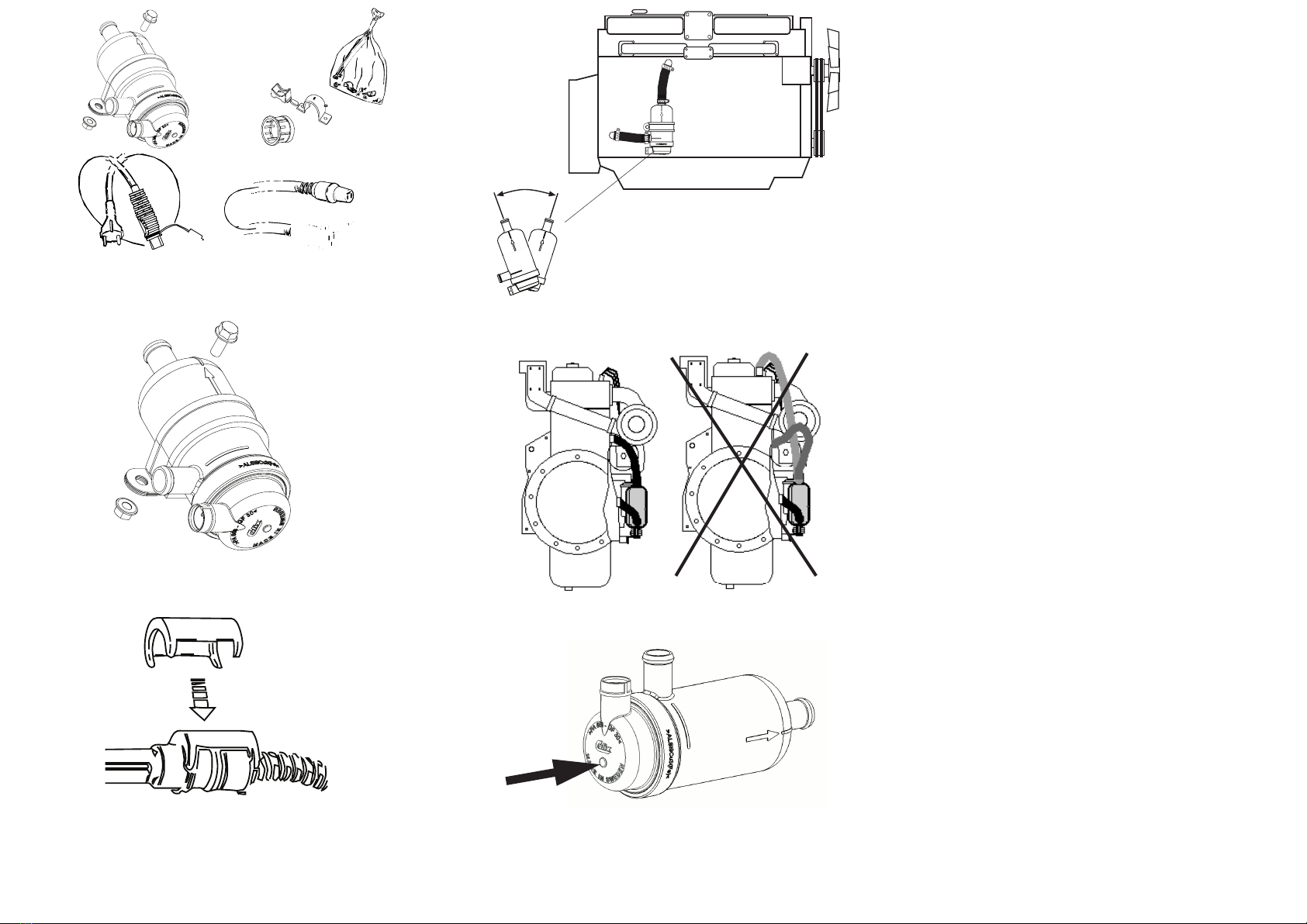
2. Monter le réchaueur aussi bas que possible. La hauteur entre sa sortie
et le point de raccordement supérieur du moteur doit être au moins
de 150 mm. Important : monter impérativement le réchaueur avec la
èche orientée vers le haut. Une légère inclinaison d’environ 15° d’un
côté ou de l’autre est néanmoins tolérée. Visser le réchaueur à l’aide
des xations fournie avec l’appareil. Voir croquis 2, 3 et 4.
3. Relier le tuyau supérieur sortant du réchaueur à un point adéquat
de la partie supérieure du moteur (capteur de température, tuyau de
chauage ou élément similaire). Plus la hauteur entre le réchaueur
et le raccordement supérieur est importante, plus le réchauage est
ecace.
4. Relier le tuyau inférieur de l’entrée de réchaueur à un point situé
en bas du bloc moteur ou du système de refroidissement (robinet de
vidange, tuyau de refroidissement inférieur ou autre élément similaire).
Le tuyau peut être monté en aval ou ou en amont du réchaueur.
5. Important: veiller à ce que les tuyaux ne présentent ni longueur de
courbures excessives, ni inclinaison irrégulière, ce genre de défaut
pouvant créer des poches d’air qui à leur tour causeront des problèmes
de circulation. Le réchaueur peut surchauer, d’où déclenchement
des protections thermiques et arrêt de l’appareil.
6. Amener le câble de raccordement dans le compartiment moteur au
niveau du réchaueur. Brancher bien à fond le câble avec le réchaueur
de façon que la bague d’étanschéité ferme hermétiquement. Huiler
légèrement le joint torique. L’assemblage en est facilité. Attention : il
est très important que le branchement s’eectue de cette manière.
C. Montage de la prise de raccordement
1. Voir l'instruction séparée.
D. Essai de fonctionnement
1. Une fois le montage eectué conformément aux instructions, remplir
le système de refroidissement. Desserrer le tuyau supérieur de rac-
cordement au moteur pour purger et contrôler l’apparition du liquide
de refroidissement. Remonter le tuyau. Terminer le remplissage, faire
démarrer puis chauer le moteur et purger enn le système de refroi-
dissement (voir notice d’instructions). Contrôler l’absence de fuites et
eectuer si nécessaire un apport complémentaire de liquide.
E. Important
1. Utiliser toujours du liquide antigel dans le système de refroidissement.
2. IMPORTANT! Utiliser exclusivement des tuyaux en catouchouc EPDM
lors du raccordement au réchaueur
3. Le réchaueur comporte des protections thermiques doubles dont le
déclenchement est le signe d’une mauvaise circulation dûe à une erreur
de montage ou à une puissance excessive de l’appareil par rapport au
volume du liquide de refroidissement. Remédier aux défauts constatés
et réinitialiser les protections thermiques en enfonçant le bouton du
couvercle (figure 5) jusqu’à perception d’un déclic. Le réchauffeur
est également équipé d’un thermostat qui se déclenche lorsque la
température du liquide de refroidissement atteint environ +80° C.
4. Brancher le réchaueur uniquement sur une prise de terre. La mise à
terre doit être continue depuis la prise de courant jusqu’au réchaueur.
5. Le câble relié au réseau doit comporter un tuyau en caoutchouc,
résistant à l’huile au minimum du type * 3 x 1,5 mm2avec une prise *
CEE (2) 57 étanche en thermoplastique. Manipuler le câble avec soin
an de ne pas l’endommager et créer ainsi des défauts d’isolation.
6. Vérier régulièrement que le câble ne soit ni endommagé ni usé. Un
câble endommagé doit être changé immédiatement.
ATTENTION
Pas utiliser pour coupler lecourant.
PH
This manual suits for next models
7
Table of contents
Languages:
Other Calix Network Hardware manuals
Popular Network Hardware manuals by other brands

Aspect
Aspect NVR-8MPOE-4 quick start guide

Huawei
Huawei EchoLife EG8247W5-8T quick start

Johnson Controls
Johnson Controls NAE55 Series installation guide

Seagate
Seagate FreeAgent GoFlex TV user guide

GW Security
GW Security 55 Series user manual

Acrosser Technology
Acrosser Technology AR-B5205 Series user manual