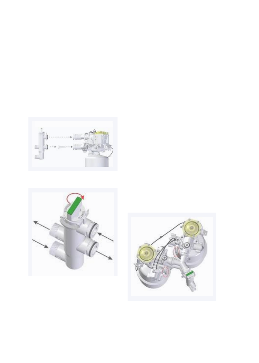
CalMag Duplex User manual

Non-Electric Softeners
OPERATING MANUAL


1.
2
3
4
5
6
7
PARTS.................................................................................................................................... 4
PRECAUTIONS................................................................................................................... 5
INSTALLATION ................................................................................................................. 6
SETTINGS...........................................................................................................................12
START UP...........................................................................................................................13
CLEANING..........................................................................................................................15
OTHER INFO.....................................................................................................................17

1
PART
S
7
9
12
1
6
8
2
13
3
5
10
11
4
1 BYPASS
8 BLENDING REGULATOR
2 VALVE HOUSING
9 HARDNESS REGULATOR
3 RESIN TANK
10 TO BRINE VALVE
4 CONTAINER FOR DEVICE AND SALT
11 TO
DRAIN
5 BRINE VALVE
(float)
12 COMMUNICATION TUBES
6 WATER INLET
13 TUBES TO BRINE VALVE
7 WATER OUTLET
4

2
PRECAUTIONS
2.
1
GENERAL
2.3 SOFTENER
The softener has to be installed
on a flat, stable base.
The softener must be installed
indoors, protected from direct
sunlight.
The softener must be installed on a
dry location and certainly not in an
acidic environment.
Do not install the softener close to
a heating source (environment
temperature must be below 40°C).
Protect softener and drain
(#11) against frost.
The Bypass is not designed to be left
behind without the softener. It is not a
shutoff valve.
The provided overflow has to be
installed and connected at all times.
Make sure you have the latest
installation manual at hand.
Read this manual carefully. If
youhave any questions or
remarks, please contact your
supplier.
Make sure you have all necessary
tools on hand before you begin
with the installation.
Follow all local legal regulations.
2.2 WATER TO BE TREATED
Check incoming pressure: minimum
1 bar (dynamic), maximum 8 bar
(static)(15 PSI- 116 PSI). If necessary
reduce incoming pressure.
The pressure behind the softener
must be at least 1 bar to ensure a
good functioning of the softener.
If this pressure of at least 1 bar can’t
be guaranteed, a “Pressure Guard” is
available at your supplier.
The water should be free of sediment,
chlorine, iron and manganese.
5

3
INSTALLATION
3.
1
RELEASE THE PRESSURE
Close the main valve and make sure
the pressure is released from the
piping. This can be done by opening
at least one tap.
3.2 CONNECT UNITS
Connect the two units by means of
the provides Y-pieces. You can find
them in the salt compartment. The
Y-piece with the filter inside, needs to
be mounted at the inlet of the valve.
(= bottom connection) The other
one must be mounted on the other
connection.
First connect the Y-piece to one unit
and afterwards to the other unit.
Secure them with the provided clips
(4 pieces). You don’t need to take the
units out of the container to do this.
3.3 CHECK COMMUNICATION
TUBES
Check if all communication tubes
are connected correctly. The two
quick-release couplings marked with
a green dot should be connected
by a communication tube (Ø0.157”);
the same should be done for the two
couplings marked with a blue dot.
See picture below.
6

3.4 INSTALL BYPASS
Cut open the main water supply in
order to install direct connections to
the softener or to install the Bypass
(recommended). Follow the arrows
on both, bypass and softener for the
water inlet and outlet.
Please note - the inlet filter
is not required in the UK.
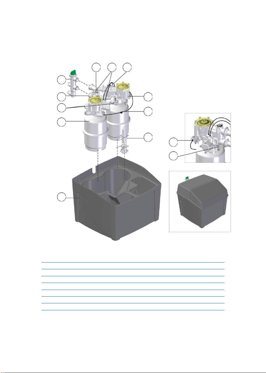
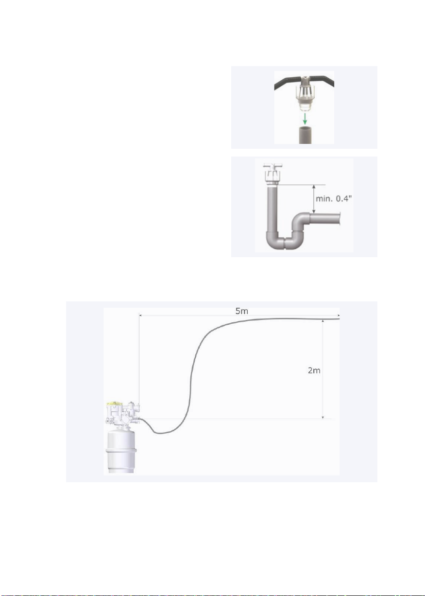
3.5 CONNECT DRAIN
Connect both drain outlets (#12) to a
local drain (with an air gap, using the
provided Open Drain Connector, see
par. 3.7) by means of the provided
13mm flexible drain pipe. In order to
guarantee that the device will keep
on functioning perfectly in the future,
this drain pipe is spirally reinforced
to avoid later blocking and/or kinks.
It is possible that both drains are
connected with each other through
a Y-piece. In this case, connect the
Y-piece to the local drain. Please
protect the drain against frost and
heat (min. temp. 5°C, max. temp.
40°C).
When another drain pipe is
used, the guarantee on the unit
is expired.
with Bypass
CAUTION: before installing the
softener,set the Bypass in “bypass”
mode, not in “service”.
7

3.6 INSTALL OVERFLOW ELBOW
Make sure to install the supplied
overflow tap. You can find the overflow
in the salt container. The overflow
needs also to be connected with the
Open Drain Connector (see par. 3.7)
First, pierce a hole (Ø21mm) in the
sidewall of the container. This hole
should be located approx. 10cm down
from the top edge of the container, on
the line shown in the drawing below.
Oncethe hole has been drilled, mount
the overflow tap and secure it with the
supplied nut. After drilling, remove all
bits of plastic that have fallen into the
container.
3.7 CONNECT DRAIN PIPES
TO OPEN DRAIN
CONNECTOR (ODC)
To connect the flexible drain pipe from
the softener (par 3.5) and from the
overflow (par 3.6) with a fixed drain
pipe, you should use the provided
O.D.C. (Open Drain Connector).
This part provides the obligatory
interruption according to the
Europeanstandard EN1717. If the
softener is connected to a fixed drain
pipe without this ODC, the guarantee
on the unit is expired.
The part with the two connections and
the transparent part are snapped into
one another. If they come apart, they
can easily be snapped back together.
8

1. Connection 1 for spirally
reinforced drain tube
Ø13mm.
2. Connection 2 for spirally
reinforced drain tube
Ø13mm.
3. Connection 3 for socket. (drain
pipe Ø40mm)
4. Connection 4 for drain pipe
Ø40mm.
1. Connect the spirally reinforced
drain tube Ø13mm, that comes
from the unit, with one of the
two
connections on the ODC. Push it on
as far as possible.
2. Connect the spirally reinforced
drain tube Ø13mm, coming from the
overflow, with the other connection.
Push it on as far as possible. This
is only possible if the overflow of
the salt container is higher than the
connection on the ODC.
9
1 2
3
4

3. If the part with the connections for
the tubes is disconnected from the
transparent part, snap them back
together. Even if the two parts are
snapped together, they still can rotate.
This means that the orientation of the
connections can be adapted. In case
the two parts keep disconnecting, you
can glue them together.
4. Now glue the complete ODC in a
fixed drain pipe Ø40mm or a socket
Ø40mm. Make sure that the ODC is
mounted horizontally and that the
partwith the connections is still
snapped in the transparent part.
Respect a minimum distance of
100mm between the bottom of the
ODC and the drain pipe. (see picture)
maximum height and distance of flexible drain hose.
10

3.8 CHECK BRINE VALVE
ASSEMBLY
Check if the brine valve is mounted
correctly. This brine valve is located in
the provided space in front of the unit.
It must sit all the way at the bottom
andwith the right side up. (see figures).
3.9 CHECK BRINE VALVE
CONNECTION
Verify if the brine valve is connected
to the softener in the right way. The
black tube Ø4mm comes from the
brine valve, and must be connected
with the small T-piece. This T-piece
connects the two pieces of brine tube
that come from both units.
Make sure that all tubes are fitted in
the connections as far as possible.
Check if there are no kinks in the tube
and that the tube is not squeezed
together.
11

4
SETTINGS
4.
1
HARDNESS REGULATOR
4.2 BLENDING REGULATOR:
= part number 8 on the
illustrationon page 4.
With the blending regulator, you can
determine the outgoing hardness.
Depending on the desired residual
hardness, set outgoing hardness with
a hex key number 5.
The setting is proportional, i.e. 1/10 –
1/5 –1/… of total incoming hardness.
= part number 9 on the illustration
on page 4.
Measure the hardness of incoming
water by means of a hardness test
kit (not supplied with the unit). The
setting of this unit is in CaCO3. (10
ppm CaCO3 = 1°fh) (1°dh = 1,78°fh)
Adjust the hardness regulator to the
measured value. This requires a hex
key number 5.
Remark: always set regulator on
bothunits to the same setting.
Remark: always set regulator on
bothunits to the same setting.
12

5 START UP
1. Leave Bypass in “bypass”
mode, open main valve and flush for
severalminutes in order to avoid
impurities from entering the
softener. When youdo not use a
Bypass, open the mainvalve slowly
as described in 5.4.
2. Fill salt container with salt in the
provided space. Use only specific
salttablets that are suitable for
softeners.
5. Open a tap behind the softener so a
flow runs through it. Some air may
flow from the tap; this comes from the
softener. This will happen only once;
at start-up. Once only water flows
fromthe tap, and no more air, close the
tap.
6. Performa manual regeneration.
•
Choose one of both units to perform a
manualregeneration. Use a hex key
number 5 to turn the program disk
(PRG) manually.
Turn PRG counter clockwise until it
is in above position. When the arrow
and the small line on the transparent
cover reach the area marked by “B”
(brining), the regeneration will
start. Immediately, the PRG willdrop
downa little (you will be able to see
and hearthis). “R” stands for refill
(refillingthe container with water at
the end of the regeneration stage).
To make sure the softener is in
regeneration, there should be a
small waterflow tothe drain, and
the water level in the container
should drop.
Let regeneration perform until it
stops automatically. The estimated
3. Add water in the salt bin until the
water level is approx. 10cm (4”) high.
(the floater on the brine valve must be
afloat).
4. Turn the bypass slowly to “service”
mode. Open the main valve when you
do not use a Bypass.
•
13

7. Place both lids on the container. First
the cover fits over the Duplex softener,
followed by the other cover which goes
on top of the salt compartment. For
future salt refills, only the front cover
has to be removed.
Connectthe overflow to the drain as well.
time is approx. 12 minutes. When
regeneration has stopped, no more
water flows to the drain. Thisis a clear
indication that the regeneration stage
is over.
Open a tap behind the softener for
several minutesto allowresidual
waterto be flushed from the tubing.
Check outgoing hardness with a
“hardnesstest kit”. Adjust blending if
necessary.
•
•
14

6
CLEANING
6.
1
UNIT (= OUTSIDE)
2. Connect the end of a 50cm part black
tubing Ø4mm with the valve. Push it in
the press fitting as far as possible. Push
it in the pressfitting as far as possible.
The otherend of the tubing Ø4mm goes
into the bottle Resin Clean.
It is only allowed to clean the unit
witha damp cloth. The use of
abrasives, detergents, soaps and / or
detergentsis never permitted.
6.2 RESIN
The only cleaning agent that is
allowed for the resin is Resin Clean.
The use of liquid acids or bases will
affect the working of the resin and
damage the synthetic material.
Failure to comply with these
regulations, a failure of the device
or accident claim will not be eligible
for warranty and stops the product
responsibility of the manufacturer.
1. Disconnect the black tubing Ø4mm
from the valve. Push the black ring on
the coupling and pull out the black
tube. (see picture)
3. Use a hex key number 5 to turn the
program disk (PRG) manually.
Turn PRG counter clockwise until it
is in the position as shown on the
picture below. When the arrow and
the small line on the transparent
cover reach the area marked by “B”
(brining), a regeneration will start.
Immediately, the PRG will drop
downa little (you will be able to see
and hear this). Now the unit will
start sucking up some Resin Clean.
15

stands for refill. (the refilling of the
containers with water at the end of
the regeneration).
5. Let regeneration perform until it
stops automatically. The estimated
time is approx. 15 minutes. When
regeneration has stopped, no more
water flows to the drain. This is a clear
indication that the regeneration stage
is over.
6. Repeat previous actions on the
other unit.
7. Open a tap behind the softener for
several minutes to allow residual
water to be flushed from the tubing.
4. Let the unit suck up 150ml Resin
Clean. After sucking up the Resin
Clean, disconnect the Ø4mm tubing
from the valve and push the black
Ø4mm tubing, coming from the brine
valve, back in the press fitting on the
valve.
The unit will now complete its
regeneration. After the suction, zone
marked with the letter ‘B’ (=Brining),
the program disk rotates until the
arrow comes into the zone marked
with the letter ‘R’. The letter ‘R’
16

7 OTHER INFO
It is recommended that a water
softener is installed by a professional.
Although the NE softener is
probably the easiest and safest
softener on the market,
it is imperative that all
necessary precautions are taken
and local legislation is
followed.
This installation guide is written to
help the professional installer keeping
in mind that this person has essential
knowledge about hydraulic softeners
and domestic plumbing.
Proper working of the softener will be
determined by proper installation.
An annual service of your softener
will guarantee optimal functioning
anda long operating life.

Non-Electric Softeners
Table of contents
Other CalMag Water Dispenser manuals
Popular Water Dispenser manuals by other brands

MOA
MOA HWD25W instruction manual

aQuatell
aQuatell Fleck 5600SXT instructions

Aqua To Go
Aqua To Go ATGARGCOOL user manual

Spectrum
Spectrum SWS Series Installation, service & operation manual

vitapur
vitapur VUV-S375B Installation instructions & owner's manual

Water Right
Water Right ISP1-1044 Installation instructions & owner's manual