Leg Extension and Setup
One leg at a time, unlock the upper
rubber grip leg lock (G) by rotating
in the direction indicated on the leg
sticker. Pull out the upper
telescoping leg section all the way
and relock leg by turning the grip
in the opposite direction. Repeat
until upper section of all three legs
are fully extended. If additional height adjustment is required,
unlock the middle (H) and lower (I) rubber grip leg locks of
each leg individually and extend sections to desired length.
Next, using both hands, pull each leg away from the
grooved center column (E) until it stops into position on the
adjustable angle leg lock (C) as shown in Figure A. Visually
confirm your equipment is properly leveled. You may need to
readjust the legs if necessary.
Low-angle Shooting
To use tripod in the standard
low-angle position (as shown at
right), simply pull the three
legs out and lock in their
widest-angle setting. Loosen
the center column lock ring (B)
by turning counterclockwise.
The center column should move up-and-down freely.
Position tripod accordingly and let the center column rest on
the ground to provide additional support. Finally, tighten the
center column lock ring by turning clockwise.
Extreme Low-angle Shooting
This tripod is equipped with a removable and reversible
grooved center column (E) allowing for extreme low-angle
positioning of your camera on the tripod. Start by removing
the spring-loaded weight hook (F) by turning counter-
clockwise. Set aside. Loosen the center column lock ring
(B) by turning counterclockwise. Then remove the center
column from tripod by pulling upward. Next, replace the
center column from underneath the tripod, making sure the
column’s groove is properly aligned. Tighten the center
column lock ring by turning clockwise. Then, replace the
spring-loaded weight hook on the center column by turning
clockwise. And finally, position and lock the tripod legs into
the widest-angle setting that is practical for your application.
Additional Features
Each of the three tripod legs feature rubber feet with
retractable stainless steel spikes, as shown in Figure B.
Depending on your shooting conditions, you may need to
switch back-and-forth. Simply turn the rubber feet clockwise
or counterclockwise.
This tripod features fully invertible legs that allow for
compact storage (Figure D). Simply position legs upward and
adjust the center column and ball head to nest in between legs.
A
B
C
D
E
Ball Head
F
G
H
I
J
Figure A
Figure B
OPERATING INSTRUCTIONS
www.calumetphoto.com
Center Column Height
Adjustment
To release and raise the center column,
simply loosen the center column lock
ring (B) by turning counterclockwise
and lift up on center column to desired
height. Relock center column by turning
the center column lock ring clockwise.
Leg Angle Adjustment
Each leg can be set
to two different angles of
spread. Pull each leg away
from the center column
until it is seated into the
first position. To change the
angle of a leg, push leg in slightly while holding the closed
cell foam grip (D). Next, push down the adjustable angle leg
lock (C) using your thumb and begin to pull the leg outward.
Immediately release leg lock and continue pulling leg until
the adjustable angle leg lock seats into the second position.
To return to the original position, simply push leg back in
towards center column and leg lock will automatically snap in
place. Pull leg out slightly to fully seat into position.
Note: The legs are never fully locked and can be moved
inward at any time, regardless of the angle adjustment
position setting.
CAUTION: Care should always be taken when considering
shooting locations, or the use of long lenses or heavy
equipment. For additional stability, Calumet recommends
the use of additional weight mounted to the center
column hook (F) whenever possible.
Figure D
Figure C
L
N
M
K
O
P
Q
Attaching Camera to the
Quick-Release (QR) Plate
First remove the QR plate (K) from
the head by rotating the safety lock
(M) clockwise until it clicks. Then
rotate the locking lever (L) clockwise
until it stops and the QR plate pops up. Mount the the QR plate (K)
to the camera by screwing the 1/4”-20 male threaded mount into
the camera’s base-plate mount using the pop-up handle on the
under side of QR plate. Before fully tightening, be sure that
camera is parallel to the plate with the lens side of the camera
over the small hole in the QR plate. When fully tightened, replace
pop-up handle flat against QR plate. An optional 3/8”-16 QR plate
(CK7002) is available from Calumet.
Mounting Camera to
the Ball Head
With camera facing forward, insert
the QR plate under the front lip on
top of the ball head and push down
on the camera until the locking lever
(L) clicks into locking position, holding plate in place. Make
sure the plate is securely locked in place by rotating the safety
lock (M) counterclockwise into its locked position.
To remove the camera from the ball head, first release the
safety lock and, while holding the camera securely in one hand,
rotate the locking lever clockwise until plate pops up and is
released from head.
Using the Ball Head (Figure C)
The ball head is very compact and easy to use, and offers solid
camera support with fluid smooth movements. It features a
single ball-locking knob (P) with an adjustable drag control
screw (O), and a separate pan-control lock (N). The calibrated
panning scale (Q) allows you to reference any movements. There
is a convenient slot on the ball head that allows you to change
your camera from horizontal to vertical format. To alter the
position of your camera, simply turn the single ball-locking knob
counterclockwise. The further you turn the knob, the looser the
friction on the ball becomes, allowing you quicker and larger
movements.
You can increase or decrease the amount of friction on the
ball with the adjustable drag control screw. First, turn the single
ball-locking knob (P) clockwise to fully lock ball. Then rotate the
adjustable drag control screw (O) clockwise to increase friction,
or counterclockwise to decrease. Test your setting by loosening
the single ball-locking knob. You may need to repeat this
procedure to find the desired setting when changing equipment.
Note: Always support the camera while loosening the single
ball-locking knob. Be sure the single ball-locking knob is fully
locked after setting the adjustable drag control screw. Do not
overtighten knobs.
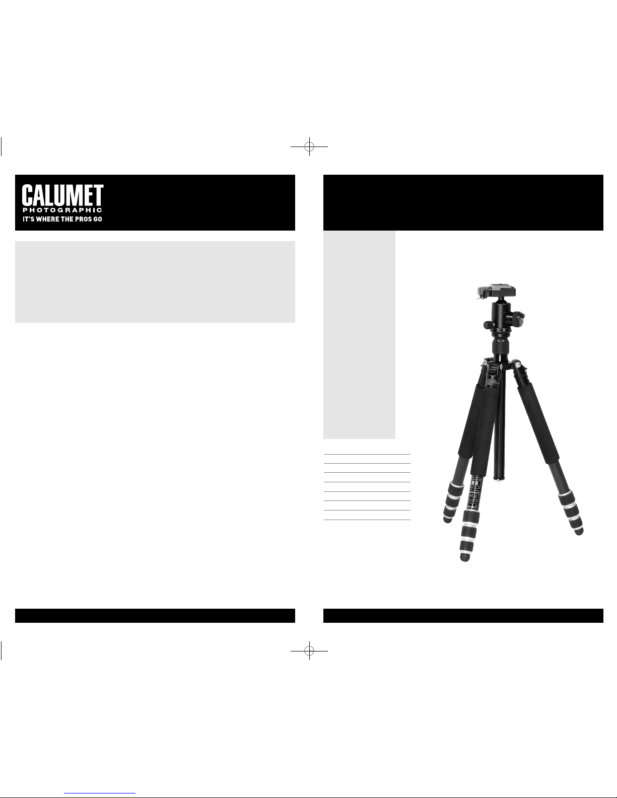
calumet 8121 tripod
with ball head