Calumet
Large Lens Gimbal Head
OPERATING INSTRUCTIONS
www.calumetphoto.com
Balancing Your Camera/Lens On the
Gimbal Head
The gimbal design makes it possible to rotate your lens
around its center of gravity with utmost precision and
safety. Follow this simple procedure to ensure that your
gimbal head will provide fluid-smooth, virtually
weightless, pan and tilt movements.
Start by loosening the Lens Platform Height Adjustment
Lock Knob by turning counterclockwise. Adjust up or
down until center of lens is centered to the adjustment
knob
(figure A).
Once positioned, tighten knob by turning
clockwise.
Now you need to balance the camera/lens from front-to-
back. While supporting the lens, slowly loosen the
QR Lens Mounting Plate Lock Knob by turning
counterclockwise. Carefully slide the camera/lens
forward or backward until balanced
(figure A).
Then
tighten the QR Lens Mounting Plate Lock Knob by
turning clockwise.
Mounting Gimbal Head to Tripod
Start by locking the Pan/Drag Adjustment Knob by turning
clockwise. This will lock the head to the Pan Spool. Mount
the head on a tripod by attaching the Pan Spool base to the
3/8" male thread of the tripod. Tighten it until it is firmly
secure to the tripod. DO NOT OVERTIGHTEN! To prevent the
gimbal head from accidently unscrewing during use, tighten
hex screws on the underside of the tripod platform. NOTE:
Not all tripods have this security feature.
Removing the Quick-Release (QR) Lens Mounting
Plate from the Gimbal Head
Your unit may have shipped with the QR lens mounting plate
attached. Remove by simply turning the Lens Mounting Plate
Lock Knob counterclockwise.
Attaching the Lens to the Quick-Release (QR)
Lens Mounting Plate
The QR lens mounting plate comes with two 1/4"-20 and one
3/8"-16 mounting screws. Determine which screw(s) are
needed for your lens. NOTE: Some lenses can utilize more
than one mounting screw for greater stability. Remove any
unused mounting screws by sliding along slot, towards the
circular end of the slot, and turn counterclockwise. Store any
unused mounting screws.
Position the QR lens mounting plate (with rubber grip side
towards lens) over the lens mount. Align appropriate
mounting screw(s) with the threaded holes in the lens
mount. Tighten mounting screws by turning clockwise,
making sure the QR lens mounting plate is centered onto
lens. DO NOT OVERTIGHTEN!
Mounting the Camera/Lens to the Gimbal Head
The tripod should be adjusted, locked into position, and
weighted (if necessary) prior to mounting the lens. Using
two hands, carefully position the camera/lens and the QR
lens mounting plate into the dovetail slots of the gimbal
head’s mounting platform. Center the QR lens mounting
plate and firmly lock into place by turning the QR Lens
Mounting Plate Lock Knob clockwise.
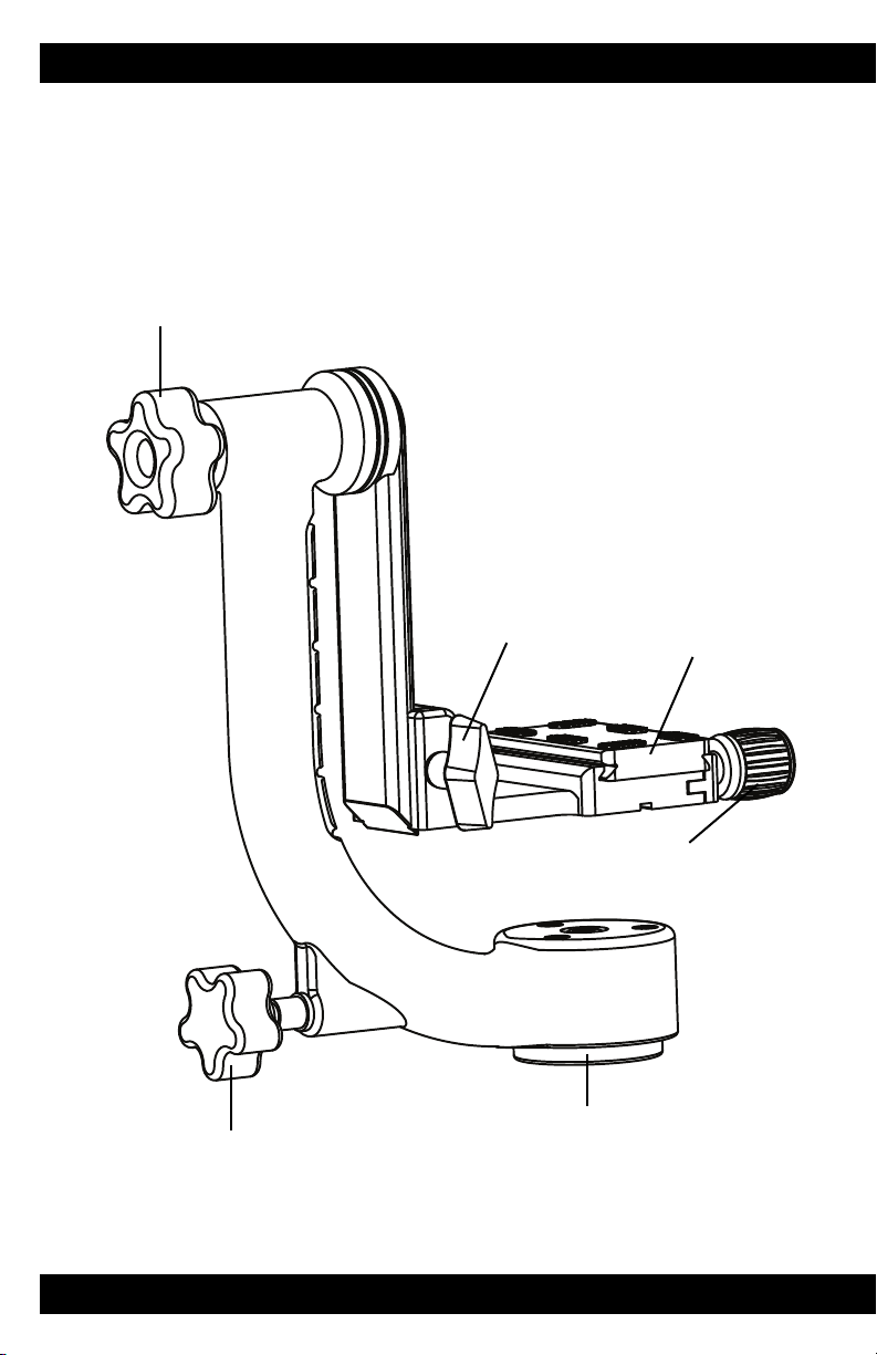
Tilt / Drag
Adjustment Knob
Lens Platform
Height Adjustment
Lock Knob Quick-Release (QR)
Lens Mounting Plate
Pan / Drag
Adjustment Knob
Pan Spool
Lens Mounting Plate
Lock Knob
figure A
Positioning the camera/lens for proper balance.
figure B
A properly balanced camera/lens should tilt
up-and-down effortlessly with the touch of a finger, and
return to its original starting position, as shown in
(figure A).
Camera/Lens Center of Gravity
You may need to repeat the above procedure
several times, making slight adjustments, in
order to achieve perfect balance.
TIP!
CAUTION! USE EXTREME CARE WHEN HANDLING
YOUR VALUABLE EQUIPMENT. HAVE SOMEONE
ASSIST IN ATTACHING EQUIPMENT TO GIMBAL
HEAD WHEN POSSIBLE. BE SURE ALL KNOBS ARE
FULLY LOCKED PRIOR TO USE OR WHEN MAKING
ANY ADJUSTMENTS.
Pan and Tilt Drag Adjustment Knobs
These knobs allow you to control the amount of
equipment drag when following a subject in motion.
Simply turn clockwise (increase) or counterclockwise
(decrease) to your preference.
CK7075_manual.qxd 12/4/09 5:06 PM Page 3


