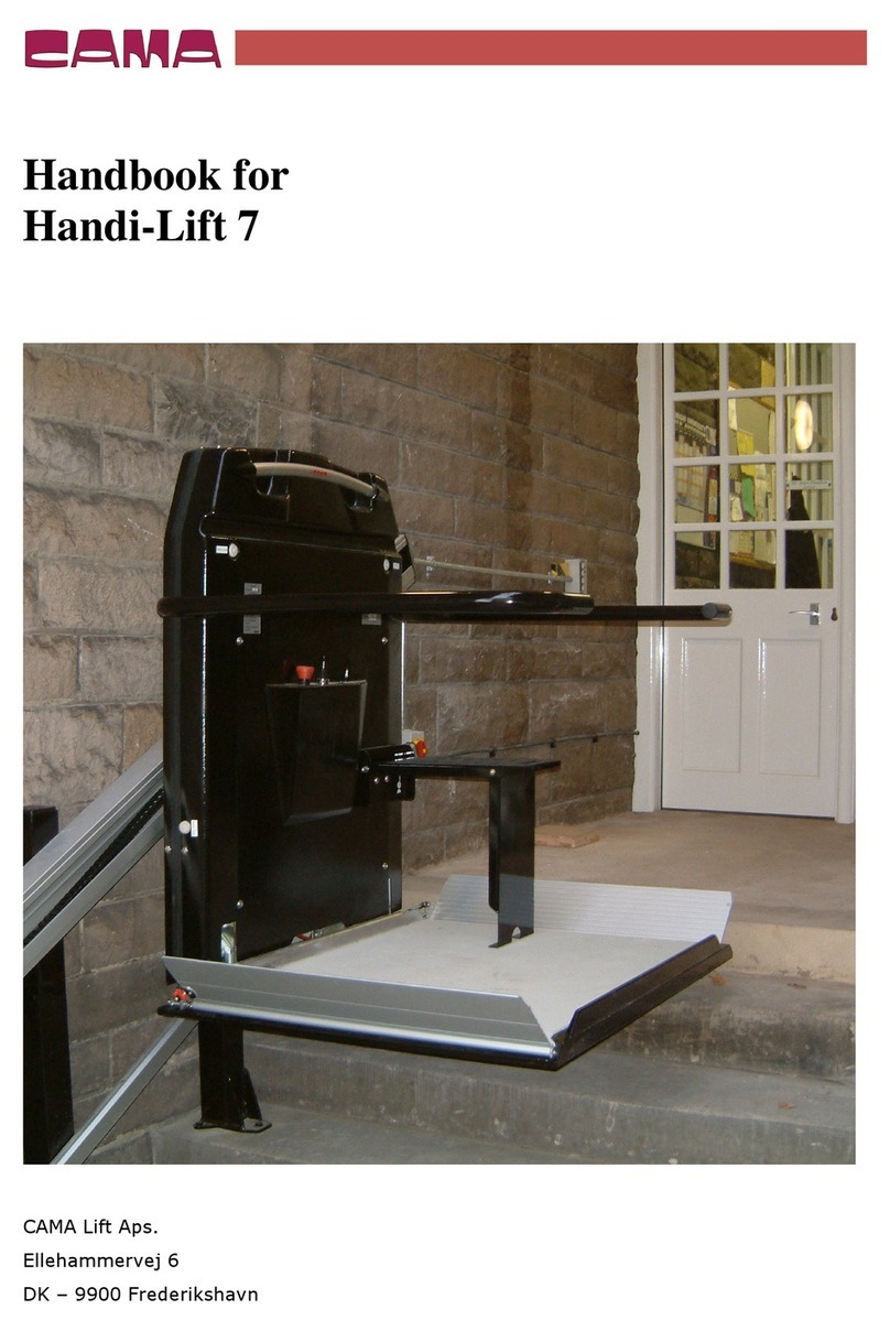
Cama Handi-Lift ML7 User manual

Installation manual
For Handi-Lift ML7
Original Version

Handi
-
Lift ML7
© 20
2
1
Page
2
Version
1.
2
Table of content
1 Introduction .............................................................................................. 3
1.1 Check the parts and drawing .................................................................. 3
1.2 Electrical installation ............................................................................. 3
Forces on the building ................................................................................ 4
Install the tower ........................................................................................ 4
3.1 Tower positioning ................................................................................. 4
Installing the lift unit .................................................................................. 7
4.1 Attach the back frame to the tower ......................................................... 7
4.2 Connect the electrical ........................................................................... 8
4.3 Connect the platform to the back frame ................................................... 9
4.4 Connect the power ............................................................................. 10
4.5 Load cell adjustment ........................................................................... 11
4.6 Handicap symbol ................................................................................ 12
Filling oil ................................................................................................ 12
Final touch ............................................................................................. 13
Install the gate ........................................................................................ 14
Installation test certificate ......................................................................... 17
Declaration A .......................................................................................... 18

Handi
-
Lift ML7
© 20
2
1
Page
3
Version
1.
2
1 Introduction
1.1 Check the parts and drawing
Before you start installing please read this installation manual.
Check the received parts for transport damage.
Next, study carefully the installation drawing that comes with the lift to ensure that all
dimensions are correct and corresponds to the installation site.
1.2 Electrical installation
If the drawing does not show where to install the Control boxes, please sort out where
they all go. Make sure that the electrical supply and electrical wiring for the Handi-Lift
are there before installing the tower and lift.
You need 1x230V with earth, 3x1,5 mm². The installation must be protected by a 10
Amp fuse and RCCB 30 mA. We recommend that you make a measurement of the
earth connection.
We recommend that you make a measurement of the earth connection.
Fig. 1

Handi
-
Lift ML7
© 20
2
1
Page
4
Version
1.
2
Forces on the building
LOAD &
FORCES
F
1
2946N
F
e
1129N
F
h
h
2300mm.
770N
2000mm.
870N
1800mm.
960N
1700mm.
1050N
1500mm.
1120N
1450mm.
1190N
Fig. 2
The tower is fixed to the floor and to the wall with M10x90mm (Class 8.8) Glue bolts.
Two bolts in the wall and three in the floor.
The given load forces applies for the total force when two bolts are used both places.
Please make sure the wall and floor materials can withstand the given loads.
Install the tower
3.1 Tower positioning
The tower is the first component to install. Dependent on the quality and straightness
of the wall- and ground material, the tower placement may need corrections.

Handi
-
Lift ML7
© 20
2
1
Page
5
Version
1.
2
Place the tower on the floor against the
wall.
Adjust the tower to be perpendicular to
the wall of the landing. (see fig. 3)
The distance between the centre of the
tower and the landing wall is given on the
installation drawing. You will also find the
distance labelled on the bottom face of
the tower.
The centre of the tower is clearly marked
with a “V” in the baseplate next to the
label (see fig. 3).
Fig. 3
Make sure the tower is in level (see fig. 4).
Fig. 4

Handi
-
Lift ML7
© 20
2
1
Page
6
Version
1.
2
Finally, adjust the tower to be vertical in both directions before fixing
it
to the wall
and the floor, so the landing fits.
Mount the bolts in the wall with glue as described on the glue package.
Fasten the nuts.

Handi
-
Lift ML7
© 20
2
1
Page
7
Version
1.
2
Installing the lift unit
4.1 Attach the back frame to the tower
Place the ba
ck frame of the lift on the floor
in front of the tower.
Fig.
5
Connectors and cables are put through the hole on both sides.
Fig. 6

Handi
-
Lift ML7
© 20
2
1
Page
8
Version
1.
2
Position the back frame to the mounting holes of the carriage.
Fasten the back frame using the four screws and washers.
Fig. 7
4.2 Connect the electrical
Leave the lift carriage and back frame in the lower position of the tower. Place the
platform on the floor in front of the back frame.
Pull the cables and mount the connectors as shown below.
Fig.
8
left
Fig.
8
right

Handi
-
Lift ML7
© 20
2
1
Page
9
Version
1.
2
Fig. 9a Fig. 9b
4.3 Connect the platform to the back frame
Mount the platform to the back
frame using
the two screws and nuts
(M12x160/M12x180).
If necessary, adjust the lower position of
the platform using the set screws.
Fig.
10
Plug the remote lead into the control board. Press the re-set button in order to start
up the system.
Fig. 11

Handi
-
Lift ML7
© 20
2
1
Page
10
Version
1.
2
Now install the control boxes
Adjust the limit switches, as shown in the photo:
Fig. 12
4.4 Connect the power
Fig. 13
The wires are connected to the safety cut-out as follows:
L1 is connected to terminal 2

Handi
-
Lift ML7
© 20
2
1
Page
11
Version
1.
2
N is connected to terminal 4
Earth is connected to the earth terminal
4.5 Load cell adjustment
Test the lift with max. load (Ex. 300 kg.) + 50kg. The load cell is adjusted from the
factory, however if it is necessary to adjust it, it is done by turning the load cell
sensor. This is installed at the upper cross bar on the platform, right next to where
the wiring from the platform comes up.
Fig. 13
The potentionmeter on the main PCB (R63) may not be used.

Handi
-
Lift ML7
© 20
2
1
Page
12
Version
1.
2
4.6 Handicap symbol
In public places, you need to install the international Handicap Symbol (ISO 7000)
with a minimum size of 50 mm next to each control box. See picture below:
Filling oil
It is important that you fill oil on the unit, however be careful not to overfill it.
Remember to pump the sponge.
Fig. 14

Handi
-
Lift ML7
© 20
2
1
Page
13
Version
1.
2
Final touch
Install the back cover, if there is a gate, you need to install it before the back cover,
see chapter 7:
Fig. 15
Examples of an installation:

Handi
-
Lift ML7
© 20
2
1
Page
14
Version
1.
2
Install the gate
Important: you need to install the gate in the closed position. If the gate is not in
closed position on receipt, then there is a mark on the foot plate that indicates which
position is closed. On the installation drawing you can see where to place it, please
make sure it is in level.
Fig. 16
Mark up where to drill using the holes in the foot plate:
Fig. 17

Handi
-
Lift ML7
© 20
2
1
Page
15
Version
1.
2
The gate can be connected to the lift in two different ways:
Hole in the floor: No hole – use slot in foot plate
Fig. 18a Fig. 18b
Connect the plug from the lift with the plug from the gate.
Fig. 19

Handi
-
Lift ML7
© 20
2
1
Page
16
Version
1.
2
Make sure the gate is flush with the edge of the floor and then glue and tighten the
M10x90 glue bolts.
Fig. 20
Now you are ready to test the gate. Make sure it can open and close properly.
Fig. 21a Fig. 21b

Handi
-
Lift ML7
© 20
2
1
Page
17
Version
1.
2
Installation test certificate
Description of installation
Location:
________________________________________________________________
Rated load: ____________ kg Handi-lift serial no: ______________________
Rated speed: ___________ m/s Type and year of
manufacture: _________________________
Manufacturer: CAMA Lift ApS, Ellehammervej 6, DK 9900 Frederikshavn
Contract electrical supply:
_________ V _________ Phase _________ Hz
Mains supply fuse rating: _________ A
Verification test on each machine before first use
All control devices function correctly
All
barriers, ramps, locks, hinged platforms
, guard
-
rails
and similar
devices operate correctly
Stopping
positions
of
Handi
-
Lift
is within specified limits
All electrical safety devices function correctly
The suspension elements and their
attachments are in order

Handi
-
Lift ML7
© 20
2
1
Page
18
Version
1.
2
The correct clearance dimensions and from the surrounding structure
are maintained throughout the full travel of the Handi-Lift
The
Handi
-
Lift
shall be subjected to insulation tests
Verify that the polarity of the mains supply connection is correct
T
est to verify the functional operation of the overspeed detection
device and safety gear
Verify that the mechanism for emergency/manual operates correctly
The alarm device when activated operates correctly
All notices, etc. are correctly
displayed
Undergo without failure a dynamic test to check the forces imposed
by the maximum working load
Undergo the testing of the overload detection device for wheelchair
platforms only
Declaration A
I/We certify that on ____/____/____ this Handi-Lift was installed to the latest
installation instructions and thoroughly examined and found to be free from obvious
defects and to comply with the requirements of and that the foregoing is a correct
report of the examination.
Signed: ______________________________ Qualifications: Authorised Installer
Address: ____________________________________ Date: ______________
Certificate of acceptance by purchaser/user
I/We being the purchaser/user of the Handi-Lift (serial no. _______________) have
received and fully understood, verbal and written instructions, in association with a
demonstration, from __________________________________ on its correct and
safe use.
Signed: ________________________________ Date: _______________
Table of contents
Other Cama Lifting System manuals