manuals.online logo
Brands
  1. Home
  2. •
  3. Brands
  4. •
  5. Cambridge Audio
  6. •
  7. Receiver
  8. •
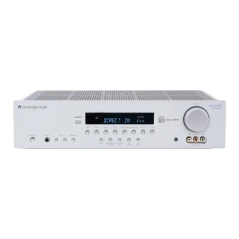
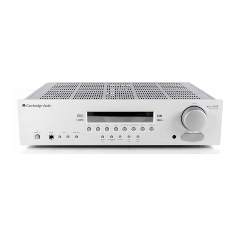
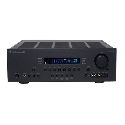
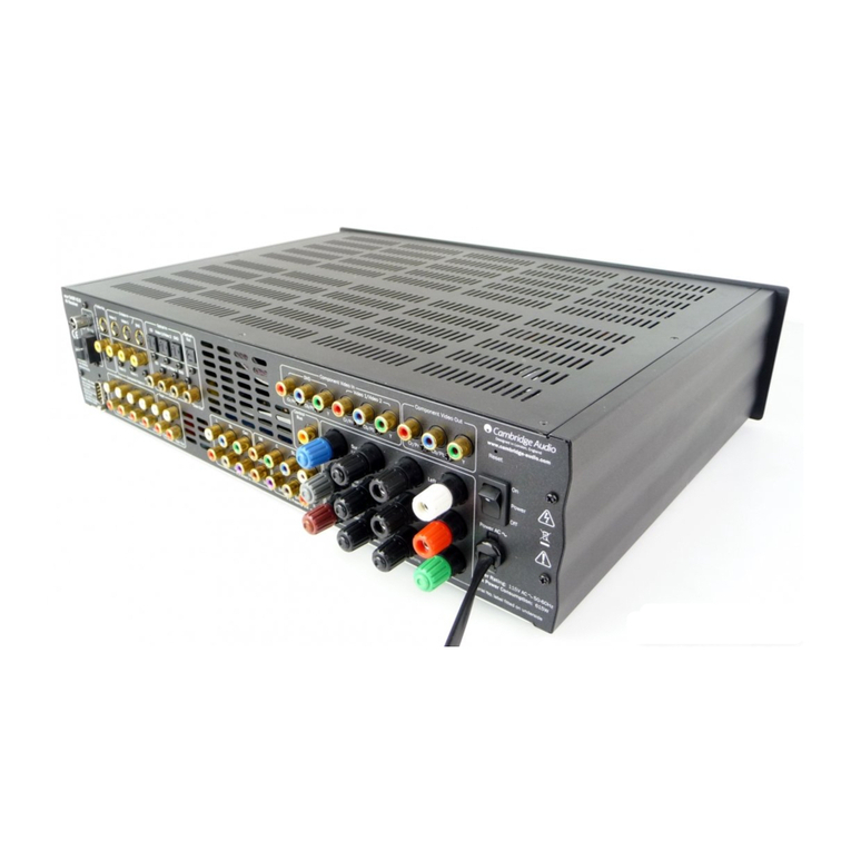
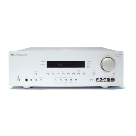
  9. Cambridge Audio Azur 540R V3 User manual

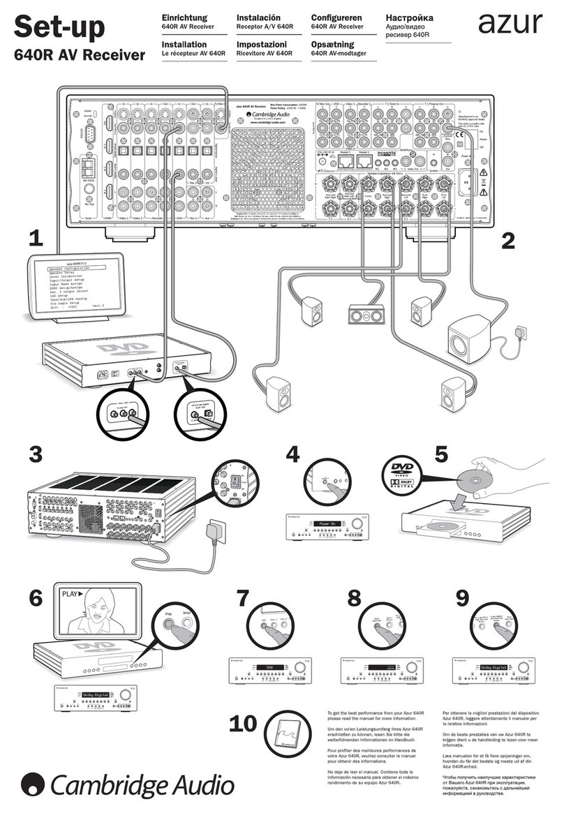
Cambridge Audio Azur 540R V3 User manual

Other manuals for Azur 540R V3

4

Other Cambridge Audio Receiver manuals

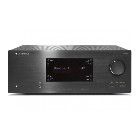
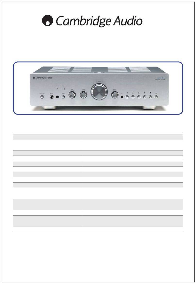
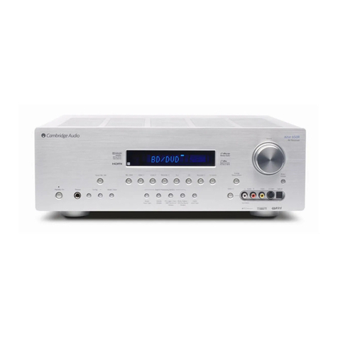
Cambridge Audio Azur 540R User manual

Cambridge Audio

Cambridge Audio Azur 540R User manual

Cambridge Audio CXR120 User manual

Cambridge Audio

Cambridge Audio CXR120 User manual

Cambridge Audio Azur 540R V3 User manual

Cambridge Audio

Cambridge Audio Azur 540R V3 User manual

Cambridge Audio Azur 340R Manual

Cambridge Audio

Cambridge Audio Azur 340R Manual

Cambridge Audio azur 540R V2.0 User manual

Cambridge Audio

Cambridge Audio azur 540R V2.0 User manual

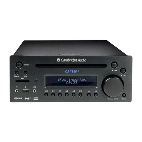
Cambridge Audio One+ User manual

Cambridge Audio

Cambridge Audio One+ User manual

Cambridge Audio Azur 640R Quick start guide

Cambridge Audio

Cambridge Audio Azur 640R Quick start guide

Cambridge Audio Azur 640R User manual

Cambridge Audio

Cambridge Audio Azur 640R User manual

Cambridge Audio Azur 640R Manual

Cambridge Audio

Cambridge Audio Azur 640R Manual

Cambridge Audio Azur 640R Manual

Cambridge Audio

Cambridge Audio Azur 640R Manual

Cambridge Audio AZUR 840A V2 User manual

Cambridge Audio

Cambridge Audio AZUR 840A V2 User manual

Cambridge Audio 640Razur User manual

Cambridge Audio

Cambridge Audio 640Razur User manual

Cambridge Audio Azur 540R V3 Manual

Cambridge Audio

Cambridge Audio Azur 540R V3 Manual

Cambridge Audio One+ User manual

Cambridge Audio

Cambridge Audio One+ User manual

Cambridge Audio azur 651R User manual

Cambridge Audio

Cambridge Audio azur 651R User manual

Cambridge Audio Azur 540R V3 User manual

Cambridge Audio

Cambridge Audio Azur 540R V3 User manual

Cambridge Audio azur 650R User manual

Cambridge Audio

Cambridge Audio azur 650R User manual

Cambridge Audio azur 551R User manual

Cambridge Audio

Cambridge Audio azur 551R User manual

Cambridge Audio Azur 640R User manual

Cambridge Audio

Cambridge Audio Azur 640R User manual

Cambridge Audio AZUR 651T User manual

Cambridge Audio

Cambridge Audio AZUR 651T User manual

Cambridge Audio One+ User manual

Cambridge Audio

Cambridge Audio One+ User manual

Cambridge Audio 340Razur User manual

Cambridge Audio

Cambridge Audio 340Razur User manual

Cambridge Audio Azur 540R V3 Manual

Cambridge Audio

Cambridge Audio Azur 540R V3 Manual

Cambridge Audio AZUR 651A User manual

Cambridge Audio

Cambridge Audio AZUR 651A User manual

Popular Receiver manuals by other brands

Televes ZAS HD SAT user manual

Televes

Televes ZAS HD SAT user manual

Realistic DX-75 Operating and service instructions

Realistic

Realistic DX-75 Operating and service instructions

Saris 4620 Assembly instructions

Saris

Saris 4620 Assembly instructions

Mini DTR 206C PVR user manual

Mini

Mini DTR 206C PVR user manual

RF Elements TwistPort manual

RF Elements

RF Elements TwistPort manual

Denon DN-200WS user guide

Denon

Denon DN-200WS user guide

Yamaha RX-V467 owner's manual

Yamaha

Yamaha RX-V467 owner's manual

Russound SaphIR 858 instruction manual

Russound

Russound SaphIR 858 instruction manual

Quasonix RDMS Firmware update procedure

Quasonix

Quasonix RDMS Firmware update procedure

Pioneer XV-HTD1 Service manual

Pioneer

Pioneer XV-HTD1 Service manual

ATZ HDMI-V2-44HE150 manual

ATZ

ATZ HDMI-V2-44HE150 manual

Sony XNV-770BT MyTomTom Specifications

Sony

Sony XNV-770BT MyTomTom Specifications

Grundig STR 7122 TWIN Service manual

Grundig

Grundig STR 7122 TWIN Service manual

Creative Blaster Modem user guide

Creative

Creative Blaster Modem user guide

Panduit ATLONA AT-OME-RX11 installation guide

Panduit

Panduit ATLONA AT-OME-RX11 installation guide

VOLTCRAFT UTPS-40 operating instructions

VOLTCRAFT

VOLTCRAFT UTPS-40 operating instructions

JVC KW-ADV794 instructions

JVC

JVC KW-ADV794 instructions

Litelink VT-1001 operating instructions

Litelink

Litelink VT-1001 operating instructions

manuals.online logo
manuals.online logoBrands
  • About & Mission
  • Contact us
  • Privacy Policy
  • Terms and Conditions

Copyright 2025 Manuals.Online. All Rights Reserved.

Gallery Court Hankey Place London SE1 4BB UK
Tel: +44 (0)20 7940 2200 Fax: +44 (0)20 7940 2233
540R v3
Issue Date: October 2007
________________________________________________________________________
SERVICE MANUAL
_______________________________________________________________________
SPECIFICATIONS:
Power Output 100 watts rms per channel,
8 ohms, two channels driven
80 watts rms per channel,
8 ohms, all six channels driven
THD <0.005% @ 1kHz
<0.04% @ 20Hz - 20 kHz
Crosstalk <-60dB
Frequency Response 20Hz – 20 kHz +/- 1dB
Audio Input Sensitivity 150mV
Audio Input Impedance 47k0hms
Digital Input Impedance 75ohms (Coaxial/SPDIF)
S/N Ratio >96dB ‘A’ weighted
Tone Control Range Bass +/- 10dB
Treble+/-10dB
FM Tuner 87.5 – 108MHz,
75 ohm coaxial aerial
AM Tuner 522 – 1629kHz
300 ohm loop aerial
Video Levels / Impedance Composite (CVBS) =
1Vp-p / 75ohm
S-Video(S-VHS)=
Y 1Vp-p / 75ohm
C 0.286 Vp-p / 75ohm
Component=
Y1Vp-p/75ohm
Cb/Cr 0.75Vp-p / 75ohm
Pb/Pr 0.75Vp-p / 75ohm
Cont.../
AP229961
Gallery Court Hankey Place London SE1 4BB UK
Tel: +44 (0)20 7940 2200 Fax: +44 (0)20 7940 2233
SPECIFICATIONS Cont.
HDMI Transfer of all resolutions up to and including
1080p @50/60Hz (1920 x 1080) supported,
with HDCP handshaking
Architecture CS42518 CODEC
CS493263 DSP
Audio Inputs 6 Line Level + Tuner
6.1DirectInput
Audio Ouputs 6 Amplified Speaker Outputs
6.1Preampoutput
1 Tape record output
Video Inputs 3 Composite , 2 S-Video
2ComponentVideo
Video Outputs 1 Composite, 1 S-Video
1ComponentVideo
Digital Inputs 4 Co-Axial, 4 Optical
Digital Outputs 1 Co-Axial, 1Optical
Stby Power Consumption <10w
Max Power Consumption 615w
Dimensions – H x W x D 150 x 350 x 430mm
Weight 9.6Kg (21.1 lbs)
AP229961
CAMBRIDGE AUDIO 540R V3
TABLE OF CONTENTS
540R V3 Service Manual Specifications 1 - 2
TableofContents 3
Troubleshooting 4
RearPanelDetails 5
Front Panel Details 6
RemoteControl 7
Connections Diagram 8
Exploded Diagram 9
Exploded Diagram Parts List 10 - 11
AvailableServicePartsList 12
Fuse Circuit Board & Headphone Circuit Board Detail 13
Fuse Circuit Board & Headphone Circuit Board 14
Mains Transformer & Power Supplies (Main Circuit Board) 15
Main Circuit Board, Output Stage 16
Main Circuit Board, Speaker Circuit Board 17
Display Circuit Board Detail 18
Display Circuit Board 19
Decoder Circuit Board (Power Supplies) 20
Decoder Circuit Board 21 - 24
HDMI Circuit Board 25 - 27
OSDCircuitBoard 28
Connect (B) Circuit Board 29
Connect (T) & OSD Circuit Boards 30
OSD & Connect (T) Circuit Boards 31
COAX Circuit Board 32 - 34
Connect (B) Circuit Board 35 - 36
Input / Output Connections 37
YUVCircuitBoard 38 – 39
Bill of Materials 40 - 48
ICDetails 49 - 51
CAMBRIDGE AUDIO 540R V3
Troubleshooting
A low hum or buzz sound can be heard:
Power cords or lighting placed near this product.
Analogue inputs not connected securely.
Sound is not audible from one channel:
Speaker connections disconnected.
Speaker set to ‘None’ in OSD setup menu.
Sound cuts off when listening to music or there is no sound even though power is ON:
Speaker impedance is less than prescribed for the 540R V3.
The unit is not adequately ventilated and may be overheating.
Low bass or “phasey” response:
Speaker polarity (+/-) of one or more speakers is reversed.
An unusual hissing noise is heard when listening to a radio broadcast in stereo, but not heard when
listening in mono:
A slight noise may be heard because the method used for modulation of FM stereo broadcasts is different than that used for mono broadcasts.
Aerial quality also effects the level of the hiss heard.
Noise is excessive in both stereo and monaural radio broadcasts:
Poor location and / or direction of the antenna.
Transmitting station is too far away.
No sound from the rear speakers:
Source being played is not recorded in surround sound.
Speaker/s set to ‘None’ in OSD setup menu.
A stereo mode has been selected.
No sound from the centre speaker:
Centre speaker has been set to ‘None’ in OSD setup menu.
A stereo mode has been selected.
No sound from the subwoofer:
Sub has been set to ‘OFF’ in the OSD setup menu or via the remote.
DTS Neo:6, DD PLII modes (which have no LFE channel) have been selected with all speakers set to ‘Large’ and Bass Augment off.
Remote Control is not working:
The batteries are flat.
The remote is too far from the receiver or out of the effective range.
No sound from speakers when connected to a digital input:
Audio input type is set to analogue (check display). Press the Audio in Type button to switch to digital.
No sound from speakers when connected to an analogue input:
Audio input type is set to digital. Press the Audio in Type button to switch to analog (check display).
Audio input type can also be set in the Input Setup menu of the OSD.
OSD not visible:
Check that the TV/Monitor is connected to the 540R V3 and is using a Composite or S-Video connection.
For more frequently asked questions (FAQ’s), technical advice and information on getting the most out of your 540R V3,
please visit the Support section on Cambridge Audio’s website:
www.cambridgeaudio.com/support.php
4
CAMBRIDGE AUDIO 540R V3
Rear Panel Connections
1
11
12
13
14
15
16
17
18
19
2
3
4
9
5
6
7
8
Power On/Off
Switches the unit on and off.
Mains power lead
Once you have completed all connections, plug the AC power lead into
an appropriate mains socket. The AV receiver is now ready for use.
Speaker terminals
Connect to loudspeakers with an impedance of between 4-8 ohms. 6.1,
5.1 or less connections can be made.
6.1 Preamp Out
Connect to the 6.1 (or 5.1) channel input terminals of another amplifier
system, separate power amps, subwoofer or active loudspeakers.
6.1 Direct In
Connect to the 6.1 (or 5.1) channel output terminals of a DVD player
with built-in surround sound decoding for playing DVD-A or SACD.
Tape/MD/CDR
Connect the Tape Play sockets to the line output terminals of a Tape
deck, MD player, CD-R etc. Connect the Tape Rec sockets to the line
input terminals of a Tape deck, MD player, CD-R etc.
Audio inputs
Connect to the audio line output terminals of a source device (eg CD,
DVD player etc).
RS232C
For use by an installer/dealer for software updates, or for control of the
540R v3 by Custom Install (C.I.) systems.
Update/Normal
For dealer use only - Switches the 540R v3 between Normal (default)
mode and Software Update mode. Do notchange the mode to Update
or make connections to it in Update mode as damage may result!
IR Emitter In
Allows modulated IR commands from multi-room systems or IR repeater
systems to be received by the 540R v3.
Rear panel connections
FM/AM antenna
All tuner antenna connections are made here. Refer to the ‘Aerial
connections’ section of this manual for more information.
HDMI
Inputs and output to a suitable TV/Monitor. The HDMI inputs can be
assigned in the OSD to the DVD, Video 1, or Video 2 sources (see later
section of this manual for more information).
TV/Mon outputs
S-Video - Connect to your television via S-Video cable to display the
picture of any S-Video connected unit.
Composite - Connect to your television via 75 ohm RCA phono cable to
display the picture of any composite video connected unit.
These outputs are also used to view the 540R v3’s on-screen setup
menu.
Component - Connect to the Cr/Pr, Cb/Pb, & Y terminals of a television
set.
Note: There is no On-Screen Display setup menu present on the
Component Video output.
Video inputs
S-Video - Connect to the S-Video outputs from the source equipment.
Composite - Connect to the Composite Video outputs from the source
equipment.
Component - Connect the Component Video outputs from the source
equipment.
Note: The preferred connection method for video sources is always
HDMI (highest quality) then Component Video then S-Video then
Composite Video. HDMI and DVD Component also support Progressive
Scan which gives better picture quality if supported by both your DVD
player and TV.
Digital Optical Inputs
Connect to the digital optical (Toslink) outputs of source equipment.
Optical Out
Connect to the digital optical (Toslink) input of an external recording
device (eg MD/CDR etc) to record from the selected digital audio source.
Digital Coax Inputs
Connect to the digital coaxial (SPDIF) outputs of source equipment.
Coax Out
Connect to the digital coaxial (SPDIF) input of an external recording
device (eg MD/CDR etc) to record from the selected digital audio source.
Heat tunnel vent grille
Allows cooling of internal circuitry. DO NOT OBSTRUCT!
FM
75Ω
AM
Loop
300Ω
Video 1 Video 2 DVD
Sur
Left
Sur
Right
Sur
Back
Left
Right
Centre
In OutCD/Aux
CD Video 1 Video 2 DVD
SB
SB
SW SW
CC
RSRSRR
LSLSLL
Power AC
6.1 Direct In
Cr/Pr Cb/Pb Y Cr/Pr Cb/Pb Y Cr/Pr Cb/Pb Y
Component Video In
2nI1nI
Tuner
RS232C
Digital Optical In
Audio In Tape/MD/CDR
L
R
Digital Coax In Coax Out
Optical
Out
TV/Mon Out
Designed in London, England
TV/Mon
Out
Serial No. label fitted
on underside www.cambridge-audio.com
Caution
Risk of electric shock.
Do not open.
Avis
Risque de choc electrique.
Ne pas ouvrir.
Achtung
Vorm öffnen des gerätes.
Netzstecker ziehen.
N1863
azur 540R v3.0 AV Receiver
Max Power Consumption: 615W
Power Rating: 230V AC ~ 50Hz
1.51.66.1 Preamp Out
Power
On
Off
In 2In 1 Out
HDMI
Do not obstruct ventilation. Ne pas obstruer la ventilation. Ventilation nicht verschließen.
Component Video
(Assignable)
(Assignable)
In
IR Emitter
Video In
In 1 (Assignable) In 2
S-VideoComposite
AЯ
46
Update
Normal
Speaker Impedance 4-8 Ohms
Manufactured
in an
ISO9002
approved
facility
This device complies with part 15 of the FCC Rules.
Operation is subject to the following two conditions:
1) This device may not cause harmful interference;
2) This device must accept any interference, including
interference that may cause undesired operation.
1 2 3 4 5
7 8 9
6 4 3
19
10
11
1213141516
18
10
17
5
CAMBRIDGE AUDIO 540R V3
Front Panel Connections
Front panel controls
Volume
Phones Tuning Mode/Store
DVD Video 1
Dolby Digital EX/
DTS ES
DSPPro Logic II/
Neo 6
Input
Mode Video 3 inputs
Video Left Right
Stereo
Modes
Video 2 Video 3 Tuner FM/AM Tape/MD/CDR CD/Aux 6.1 Direct
–+
Standby / On
azur 540R
AV Receiver
1 2 3 4
5 6 7 8 9
10 11 12 13 14 15 16 17
18
19
20
Standby/On
Switches the unit between Standby mode (indicated by dim power LED)
and On (indicated by bright power LED). Standby is a low power mode
where the power consumption is less than 10 Watts. The unit should be
left in Standby mode when not in use.
Phones
Allows for the connection of stereo headphones with a 6.35mm/¼" Jack
plug. Headphones with an impedance of between 32 and 600 ohms are
recommended.
Note: Plugging in headphones will automatically mute the main and pre-
amp outputs and select a 2-channel stereo down-mix to be created for
headphone use.
Tuning +/-
Used to tune FM/AM frequencies and skip presets in Tuner mode.
Mode/Store
Press to cycle between Tuner modes (refer to the ‘Operating
instructions’ section of this manual for more information).
Note: The 540R v3 remembers the audio and video input type and
processing mode for each individual source input. These are recalled
each time a source is selected.
Stereo Modes
Press to listen to a source in either Stereo or Stereo + Sub modes.
Dolby Digital EX / DTS ES
Press to select Dolby Digital or DTS surround modes (with suitably
encoded digital source material). These modes can only be decoded
from digital audio sources (via Coaxial or Optical inputs).
Pro Logic II / Neo:6
Press to select between various Pro Logic II/Neo:6 effects for matrix
encoded analog or digital material or for post-processing DD/DTS
material.
Note: The 540R v3 is unable to auto-detect this kind of source material
as it does not include embedded encoding type flags so manual
selection is required.
DSP
The 540R v3 can create a surround sound effect even from non-
encoded material by Digital Signal Processing (DSP). Press this button to
choose one of the following surround sound effects: THEATER, HALL,
MOVIE, MUSIC or ROOM.
Input Mode
Press this button to toggle between analog or optical/coaxial digital
input types for the currently selected source. The 540R v3 remembers
the input type selected for each source when you return to that source.
1
2
3
4
5
6
7
8
9
DVD
Press to select the DVD source equipment for output through the 540R
v3.
Video 1
Press to select the source equipment connected to Video 1 for output
through the 540R v3.
Video 2
Press to select the source equipment connected to Video 2 for output
through the 540R v3.
Video 3
Press to select a video camera recorder/video games console
connected to the Video 3 input sockets.
Tuner FM/AM
Press to select the tuner for output through the 540R v3. Once in Tuner
mode also use this button to switch between FM and AM modes.
Tape/MD/CDR
Press to select the recording device connected to the Tape/MD/CDR
input for output through the 540R v3.
CD/Aux
Press to select the CD or other source equipment connected to CD/Aux
on the rear panel for output through the 540R v3.
6.1 Direct
Press to select a 6.1 or 5.1 source (DVD-A or SACD player etc) connected
to the 6.1 Direct In sockets.
Infrared sensor
Receives IR commands from the supplied Azur remote control. A clear
unobstructed line of sight between the remote control and the sensor is
required.
Volume
Use to increase/decrease the level of the sound from the outputs of the
540R v3.
Video 3 input sockets
Allows a video camera recorder/video games console to be connected
and selected by the Video 3 source button.
10
11
12
13
14
15
16
17
18
19
20
6
CAMBRIDGE AUDIO 540R V3
Remote Control Details
Remote control
Tuner AM/FM
Selects Tuner mode. Pressing again to toggle between FM
and AM modes.
6.1 Direct
Selects the 5.1/6.1 Direct input.
PTY (Program Type Search)
Press to search by program type when in Tuner mode.
Refer to the ‘Operating instructions’ section of this manual
for more information.
APS (Auto Program Search)
Hold down for 4 seconds to allocate and memorise radio
stations automatically.
Display
Press to view the current source material and decoding
mode. When listening to FM with RDS, press to cycle
round various RDS information modes.
Stereo Mono
When listening to the FM tuner, press to alternate between
stereo and mono modes.
Store
Press to store the current frequency when in Tuner mode.
Mode
Press to select Auto/Manual or Preset tuning when in
Tuner mode.
DVD, Video 1, Video 2, Video 3, Tape
MD/CDR, CD Aux
Press the corresponding button to change the input
source.
The above button descriptions are naturally brief. Please
refer to the ‘Operating instructions’ section of this
manual for more information on the relevant functions
implemented.
The 540R v3 is supplied with an Azur Navigator remote
control. Insert the supplied AAA batteries to activate. For
full details of the various adjustment functions available
from the remote, refer to the later sections of this manual.
Standby/On
Switches the unit between On and Standby mode.
Audio In Type
Selects between analog or digital audio input for the
current source.
Stereo, PLII/NEO 6, DD EX/DTS ES, DSP Modes
See button details as listed in the ‘Front Panel Controls’
section on the previous page.
DRC (Dynamic Range Control)
Press to rotate through four dynamic range settings when
listening to Dolby Digital/DTS movie soundtracks. Refer to
the ‘Operating instructions’ section of this manual for
more information.
LFE Trim
Press to trim (adjust the level of) the Low Frequency
Effects channel using the Volume up/down buttons.
Sub On/Off
The Sub On/Off button performs temporary muting of the
Subwoofer without affecting the bass management or
speaker settings. Pressing the Sub On/Off button again or
selecting another decode mode cancels Sub Mute.
To make permanent settings to the speaker options
including the Subwoofer, use the ‘Speaker Config Menu’
in the On Screen Display (OSD).
Also, hold down and then press the volume up and down
buttons to adjust the overall sub level if desired.
On-screen Display (OSD)
Press to access the on-screen set-up menu when
connected to a monitor/screen via composite or S-video
connections.
Bass Treble
Press for bass/treble adjustment, using the Volume
up/down buttons.
Mute
Mutes the audio on the AV Receiver. Press again to cancel
mute.
Volume
Increase or decrease the volume of the AV receiver
output. Also used as up/down in the OSD setup menu.
Tune / Left & Right
Press the right arrow to increase tuner frequency/change
preset. Press the left arrow to decrease tuner
frequency/change preset. Also used to scroll left/right in
the OSD setup menus.
Enter
Used in the OSD setup menu.
Stereo
Modes
Audio In
Type
6.1
Direct
DSP
DRC
PL II
Neo 6
DD EX
DTS ES
LFE
Trim
Sub
On/Off
Tuner
AM/FM
Bass
Treble
ModeStore
Stereo
Mono
DisplayPTY APS
DVD Video 1 Video 2
Video 3 CD
Aux
Tape
MD/CDR
Enter
Vol
Vol
7
CAMBRIDGE AUDIO 540R V3
Connections Diagram 8
CAMBRIDGE AUDIO 540R V3
Exploded Diagram 9
CAMBRIDGE AUDIO 540R V3
Exploded Diagram Parts List
krameR.ytQnoitpircseD.ONtraP.leS
1 6531 1010 0010 VOLUMN KNOB AL SKIN
1BONKNMULOVPMA0000040113372
1REVOC3VA0900001113973
86X0.3BTBWERCS0300600311054
1SNELYALPSID0800010113475
1LENAPLA0240110113066
1EDIUGTHGILPMA0000030113477
85331 1010 0000 SCALEBOARD
01NMULOCBCP0000220113979
10 7631 1010 0000 MR CONTROL BOX BUTTON CUSHION
11 7331 1010 0010 MR CONTROL BOX BUTTON
1BCPENOHP10017110450021
13 5011 3014 0010 SCREW BTB3.0X14 10
14 7631 1020 0000 7MM TAC SWITCH BUTTON CUSHION
15 7331 1020 0010 7MM TAC SWITCH BUTTON
16 7631 1030 0000 4MM TAC SWITCH BUTTON CUSHION
17 7331 1030 0010 4MM TAC SWITCH BUTTON
514X0.3BTBWERCS01004003110581
1SNELRI00000201134791
1BCPNMULOV10003911450002
1BCPYALPSID10003101450012
1NOITAROCED01000101139722
1BCP3VA00013801450032
4DAPTOOF10000601139742
4TOOF01000501139752
48X0.3MB01008003210562
27 7531 1040 0000 540R front support right assy 1
1)THGIR(REVOCEDIS11001201134682
29 7531 1050 0000 540R rear support right assy 1
30 7531 1020 0000 540R front support left assy 1
88X6.2BTBWERCS00008062410513
1)TFEL(REVOCEDIS01001101134623
1REVOCPOT01000101131633
88X6.2MBWERCS01008062810543
646X0.3BTBWERCS01006003110553
1yssatfeltroppusraerR04500000301135763
1BCPESUF10010110450073
401=HNS01-SBC00000000117883
1REVOCMOTTOB01000201132693
1CVPBCP01050040807704
76=HNS6-SBC00000006017814
253=H283-TDDK00000005337824
242=LTLOB00000301139534
223=LTLOB00000101139544
1NAF16223352201954
2)3Hx4Dx01D(HSAW00000701139764
540R (V3) PARTS LIST
1
1
1
1
8
8
8
8
10