Camille Bauer EMMOD201 V2.0 User manual

Table of contents
1. Introduction ..............................................................................................................................................................2
2. Connecting devices .................................................................................................................................................3
3. Interface realization .................................................................................................................................................4
4. Measurands acquisition...........................................................................................................................................5
4.1 Present measurands .........................................................................................................................................5
4.2 Minimum / Maximum values..............................................................................................................................7
4.3 Meter contents...................................................................................................................................................9
4.4 Mean values ....................................................................................................................................................10
4.5 Mean values progression (Logger) .................................................................................................................12
4.6 Measurands overflow ......................................................................................................................................13
5. Status interrogation / remote control .....................................................................................................................14
5.1 Status interrogation .........................................................................................................................................14
5.2 Remote control of digital outputs.....................................................................................................................14
5.3 Setting tariff situation.......................................................................................................................................14
5.4 Synchronization via bus interface ...................................................................................................................14
5.5 Firmware versions and device type ................................................................................................................15
6. Resetting measurands...........................................................................................................................................16
6.1 Resetting minimum and maximum values ......................................................................................................16
6.2 Setting / resetting meters ................................................................................................................................17
7. Configuration .........................................................................................................................................................18
Appendix: Display matrices, system dependent.........................................................................................................24
The basics for the understanding of the MODBUS®communication is summarised in a separated document:
"Modbus Basics.pdf" (available via our Website http://www.camillebauer.com)
Within that document you will find detailed telegram examples, also for Modbus/TCP communication.
MODBUS
®
- Modbus is a registered trade mark of Schneider Electric. Detailed protocol specifications are available via the
Website http://www.modbus.org
Modification Date Vis.: Type: EMMOD201 Nr.: 1 / 26 gez.: 26.11.02 RR
27.02.09 RR Description: Interface definition EMMOD201 V2.0 Zeichnr.: W2414e

Modification Date Vis.: Type: EMMOD201 Nr.: 2 / 26 gez.: 26.11.02 RR
27.02.09 RR Description: Interface definition EMMOD201 V2.0 Zeichnr.: W2414e
1. Introduction
The devices of the A200 series of multi-functional power meters may be equipped with an optional extension module. Within this
document the communication with the module EMMOD201 is shown. It provides a switch able RS232 / RS485 interface,
memory for a logger and a digital input.
Basically three different operating modes may be realized:
- Standalone: The module is used for configuring the device only. There is no permanent connection to a master (PC) or it is
not fixed all the time.
- Bus service: Up to 32 devices may be interconnected via RS485 interface. Measured data are requested permanently via a
MODBUS master.
- Full device control via bus: Beside the interrogation of measurands the synchronization of the mean power values, tariff
switching and digital output driving (on-site alarming) may be performed via bus interface. The MODBUS master is fully
responsible for a permanent control of the devices and acquires measurands periodically.
The following functions can be performed using the extension module:
- Interrogation of device features
- Modification of device features
- Acquisition of present measurands
- Acquisition of integrated mean-power values
- Interrogation / setting / resetting of meter contents
- Resetting minimum / maximum values
- Acquisition of mean-power values stored in the logger
- Synchronization, tariff switching or direct output driving of digital outputs via bus interface
This document describes all these functions. For communication protocols according to the MODBUS specification are used.
However, normally you will work with an existing hardware and / or software platform. Therefore we will give a help to various
users which chapters of this document are of help for him.
Hardware installer
2. Connecting devices
MODBUS®tool user
4. Measurand acquisition
Engineer who wants to realize an independent measurand acquisition
4. Measurand acquisition
5. Status interrogation / remote control
6. Resetting measurands
Engineer who wants to realize independent configuration software
3. Interface realization
7. Configuration

2. Connecting devices
RS485: MODBUS interface
The switch on the extension module has to be in position RS485.One should use twisted signal wires cables and pay attention
to the polarity. GND can be connected with a wire or the cable screen. Screened cables must be used in an environment with
interference.
If long wires (> 10m) are used, termination resistors of each 120 Ohm are necessary on both bus ends. Additionally supply
resistors of 500...1000 Ohm to signal GND and +5V are required. Normally these supply resistors are part of the bus master
interface.
Attention: Simple interface converters have no built-in supply resistors. Devices with supply resistors are e.g. W&T 13601 (PC
card) or W&T 86201 (converter) of Wiesemann & Theis GmbH.
Beware of long stubs, a simple line network is ideal. Up to 32 devices (including the master) may be interconnected.
EMMOD201
MASTER
EMMOD201
+ 3.3/+5V
Rs
Rs
Rt
Rt
30
31
32
1)
Rb
+6V
30
31
32
33
34
Vz
EMMOD201
123
31
Rb
+6V
30
31
32
33
34
Vz
RS485 Bus
Rx/Tx-,B
Rx/Tx+,A
GND
EMMOD201
30
31
32
Dig.Inp.
Dig.Inp.
++
+---
+
-
HT/LT,
Sync.
+
+-
-
All devices must use the same bus settings (baudrate, parity control) but a unique device address. These settings may
be performed locally at the device or via RS232 interface.
1) One ground connection only. This is possibly already made at the master (PC).
Rt Termination resistors 120 Ohm
Rs Bus supply resistors 500...1000 Ohm
Rb Contact input supply resistors 4.5kOhm
Vz 6.2V zener diode for protection
RS232: Programming interface
The switch on the extension module has to be in position RS232. Using a PC, the software A200plus and an interface adapter
cable RS232 (order no. 152 603) the configuration settings can be clearly and easily made. All the bus functions are available.
However, interconnetion of more than one device is impossible.
Modification Date Vis.: Type: EMMOD201 Nr.: 3 / 26 gez.: 26.11.02 RR
27.02.09 RR Description: Interface definition EMMOD201 V2.0 Zeichnr.: W2414e

Modification Date Vis.: Type: EMMOD201 Nr.: 4 / 26 gez.: 26.11.02 RR
27.02.09 RR Description: Interface definition EMMOD201 V2.0 Zeichnr.: W2414e
3. Interface realization
Supported functions
Code MODBUS®function Used for ...
03HREAD HOLDING REGISTERS - Acquisition of measurands, meter contents, mean-values,
logger data
- Configuration data upload
08HDIAGNOSTIC - By means of the sub-function 0 the connection to the
device may be tested.
10HPRESET MULTIPLE REGISTERS - Configuration
- Setting /resetting meters
- Resetting minimum/maximum values
Supported transmission modes
* RS232 Fixed settings: 9600Bd, 1 start bit, 8 data bits, even parity, 1 stop bit, device address 255
* RS485 Baudrate 1200, 2400, 4800, 9600 or 19200 Bd (configurable)
Char. format: 1 start, 8 data, even parity, 1 stop bit
1 start, 8 data, odd parity, 1 stop bit
1 start, 8 data, no parity, 2 stop bit
1 start, 8 data, no parity, 1 stop bit (often used, but not in accordance with MODBUS specification)
The settings of the transmission parameters and the device address for the RS485 interface may be performed via the front
panel of the device or by software using the RS232 interface.
Further applicability
Via the module EMMOD201 a Modbus/TCP communication via Ethernet may be realized as well. Up to 32 devices may be
interconnected via RS485. They can be connected to an Ethernet network using a Modbus RTU/TCP gateway.
The basics for the understanding of the MODBUS®communication is summarised in a separated document:
"Modbus Basics.pdf" (available via our Website http://www.camillebauer.com)
Within that document you will find detailed telegram examples, also for Modbus/TCP communication.

Modification Date Vis.: Type: EMMOD201 Nr.: 5 / 26 gez.: 26.11.02 RR
27.02.09 RR Description: Interface definition EMMOD201 V2.0 Zeichnr.: W2414e
4. Measurands acquisition
The power monitoring devices acquire the measurands of an electrical power system. These measurands and derived quantities
may be interrogated via the extension module EMMOD201. This information can be divided as follows:
1. Present measurands
2. Minimum / maximum values
3. Meter contents
4. Mean-power values (integrated for a synchronization interval)
5. Progression of mean-power values (Logger)
4.1 Present measurands
4.1.1 General present measurands
Register
address
Measurand single-phase / 3 or 4-wire
balanced load systems
3-wire unb.
system
4-wire unb.
system
100 U ☻- -
102 U1N - - ☻
104 U2N - - ☻
106 U3N - - ☻
108 U12 - ☻☻
110 U23 - ☻☻
112 U31 - ☻☻
114 I ☻- -
116 I1 - ☻☻
118 I2 - ☻☻
120 I3 - ☻☻
122 Iavg ☻- -
124 I1_avg - ☻☻
126 I2_avg - ☻☻
128 I3_avg - ☻☻
130 IN - - ☻
132 P1 - - ☻
134 P2 - - ☻
136 P3 - - ☻
138 P ☻☻☻
140 Q1 - - ☻
142 Q2 - - ☻
144 Q3 - - ☻
146 Q ☻☻☻
148 S1 - - ☻
150 S2 - - ☻
152 S3 - - ☻
154 S ☻☻☻
156 F ☻☻☻
158 PF1 - - ☻
160 PF2 - - ☻
162 PF3 - - ☻
164 PF ☻☻☻
166 Umean - ☻☻A230 only: Mean value of voltages
168 Imean - ☻☻A230 only: Mean value of currents
170 UNE - - ☻A230 only: Zero displacement voltage
172 Pint_tnd1 ☻☻☻A230 only: Mean power value P incoming (trend)
174 Qint_tnd1 ☻☻☻A230 only: Mean power value Q ind. / incoming (trend)
176 Sint_tnd ☻☻☻A230 only: Mean power value S (trend)
178 Pint_tnd2 ☻☻☻A230 only: Mean power value P outg. (trend)
180 Qint_tnd2 ☻☻☻A230 only: Mean power value Q cap. / outg. (trend)
The active measurand of the reactive power intervals for the A230 arise from the configuration in 'Disp_Mode' (see chapter 7).
Legend: ☻= Valid measurand - = Not used (value=0.00)
All values are 32-bit float numbers (2 registers for each value), scaled on primary values.

Modification Date Vis.: Type: EMMOD201 Nr.: 6 / 26 gez.: 26.11.02 RR
27.02.09 RR Description: Interface definition EMMOD201 V2.0 Zeichnr.: W2414e
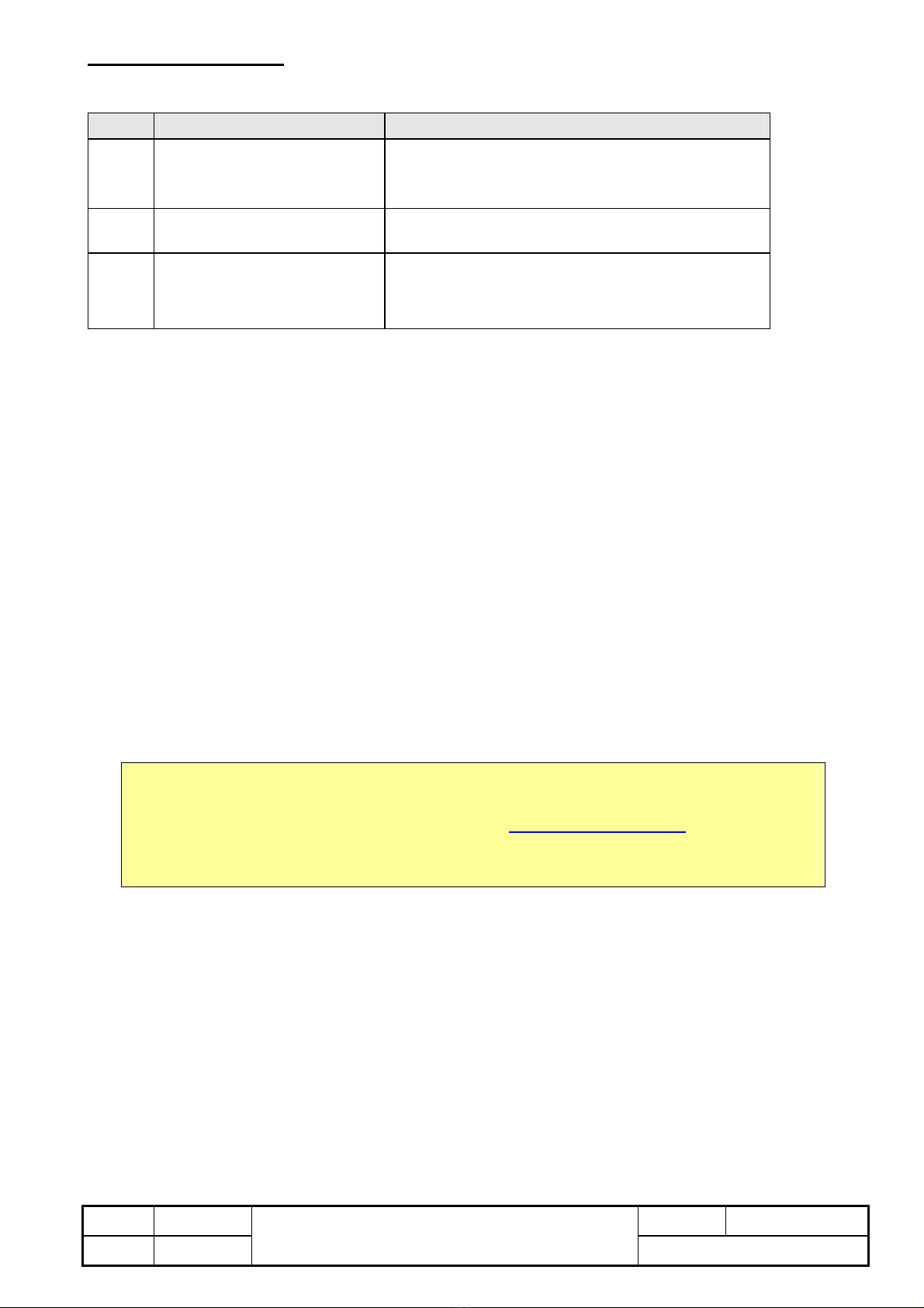
4.1.2 Present measurands unbalance / THD (A230 only)
Register
address
Measurand single-phase / 3 or 4-wire
balanced load systems
3-wire unb.
system
4-wire unb.
system
184 unb.U - - ☻Unbalance factor
185 THD.Ux U U12 U1 Harmonic content U / U12 / U1
186 THD.Ux - U23 U2 Harmonic content U23 / U2
187 THD.Ux - U31 U3 Harmonic content U31 / U3
188 THD.Ix I I1 I1 Harmonic content I / I1
189 THD.Ix - I2 I2 Harmonic content I2
190 THD.Ix - I3 I3 Harmonic content I3
Legend: ☻= Valid measurand - = Not used (value=0.00)
All these values are unsigned 16-bit numbers (1 register per value). 1000 corresponds to 100%.
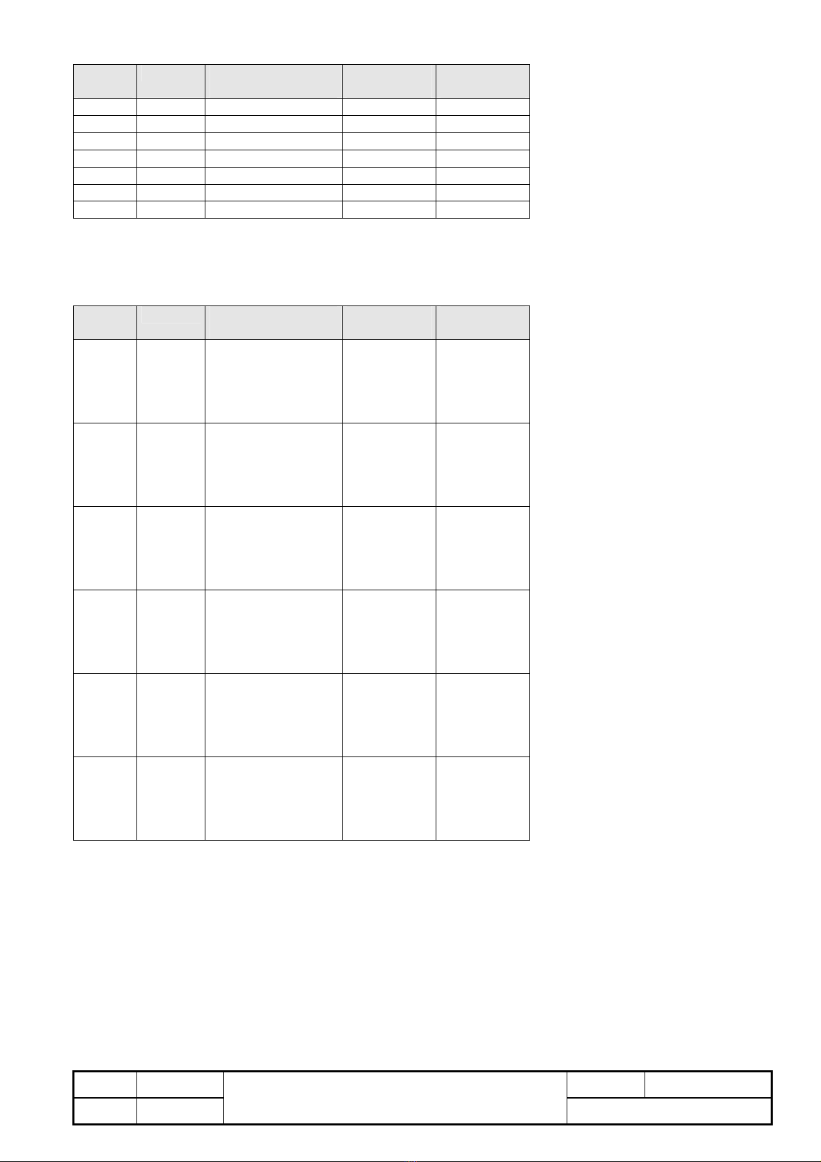
4.1.3 Present harmonic contents (A230 only)
Register
address
Measurand single-phase / 3 or 4-wire
balanced load systems
3-wire unb.
system
4-wire unb.
system
600 H2.Ux U U12 U1N 2nd harmonic content
601 H3.Ux U U12 U1N 3rd harmonic content
... Hn.Ux U U12 U1N nth harmonic content
612 H14.Ux U U12 U1N 14th harmonic content
613 H15.Ux U U12 U1N 15th harmonic content
614 H2.Ux - U23 U2N 2nd harmonic content
615 H3.Ux - U23 U2N 3rd harmonic content
... Hn.Ux - U23 U2N nth harmonic content
626 H14.Ux - U23 U2N 14th harmonic content
627 H15.Ux - U23 U2N 15th harmonic content
628 H2.Ux - U31 U3N 2nd harmonic content
629 H3.Ux - U31 U3N 3rd harmonic content
... Hn.Ux - U31 U3N nth harmonic content
640 H14.Ux - U31 U3N 14th harmonic content
641 H15.Ux - U31 U3N 15th harmonic content
642 H2.Ix I I1 I1 2nd harmonic content
643 H3.Ix I I1 I1 3rd harmonic content
... Hn.Ix I I1 I1 nth harmonic content
654 H14.Ix I I1 I1 14th harmonic content
655 H15.Ix I I1 I1 15th harmonic content
656 H2.Ix - I2 I2 2nd harmonic content
657 H3.Ix - I2 I2 3rd harmonic content
... Hn.Ix - I2 I2 nth harmonic content
668 H14.Ix - I2 I2 14th harmonic content
669 H15.Ix - I2 I2 15th harmonic content
670 H2.Ix - I3 I3 2nd harmonic content
671 H3.Ix - I3 I3 3rd harmonic content
... Hn.Ix - I3 I3 nth harmonic content
682 H14.Ix - I3 I3 14th harmonic content
683 H15.Ix - I3 I3 15th harmonic content
All harmonic values are unsigned 16-bit numbers (1 register per value). 1000 corresponds to 100%. The values refer to the
fundamental wave, which is fixed to 100%.

Modification Date Vis.: Type: EMMOD201 Nr.: 7 / 26 gez.: 26.11.02 RR
27.02.09 RR Description: Interface definition EMMOD201 V2.0 Zeichnr.: W2414e
4.2 Minimum / Maximum values
4.2.1 Minimum / Maximum values 1
Register
address
Measurand single-phase / 3 or 4-wire
balanced load systems
3-wire unb.
system
4-wire unb.
system
200 Umax ☻- -
202 U1Nmax - - ☻
204 U2Nmax - - ☻
206 U3Nmax - - ☻
208 U12max - ☻☻
210 U23max - ☻☻
212 U31max - ☻☻
214 I1max ☻- -
216 I1max - ☻☻
218 I2max - ☻☻
220 I3max - ☻☻
222 Iavgmax ☻- -
224 I1avgmax - ☻☻
226 I2avgmax - ☻☻
228 I3avgmax - ☻☻
230 INmax - - ☻
232 P1max - - ☻
234 P2max - - ☻
236 P3max - - ☻
238 Pmax ☻☻☻
240 Q1max - - ☻
242 Q2max - - ☻
244 Q3max - - ☻
246 Qmax ☻☻☻
248 S1max - - ☻
250 S2max - - ☻
252 S3max - - ☻
254 Smax ☻☻☻
256 Umin ☻- -
258 U1Nmin - - ☻
260 U2Nmin - - ☻
262 U3Nmin - - ☻
264 U12min - ☻☻
266 U23min - ☻☻
268 U31min - ☻☻
270 PFmin.inc.ind ☻☻☻A230 only: Incoming
272 PFmin.inc.cap ☻☻☻A230 only: Incoming
274 PFmin.out.ind ☻☻☻A230 only: Outgoing
276 PFmin.out.cap ☻☻☻A230 only: Outgoing
278 Fmin ☻☻☻A230 only
280 Fmax ☻☻☻A230 only
282 UNEmax - - ☻A230 only
Legend: ☻= Valid measurand - = Not used (value=0.00)
All values are 32-bit float numbers (2 registers for each value), scaled on primary values.

Modification Date Vis.: Type: EMMOD201 Nr.: 8 / 26 gez.: 26.11.02 RR
27.02.09 RR Description: Interface definition EMMOD201 V2.0 Zeichnr.: W2414e
4.2.2 Maximum values of THD / harmonic contents (A230 only)
Register
address
Measurand single-phase / 3 or 4-wire
balanced load systems
3-wire unb.
system
4-wire unb.
system
700 unb.Umax - - ☻Unbalance U maximum
701 THD.Uxmax U U12 U1N
702 THD.Uxmax - U23 U2N
703 THD.Uxmax - U31 U3N
704 THD.Ixmax I I1 I1
705 THD.Ixmax - I2 I2
706 THD.Ixmax - I3 I3
707 H2.Uxmax U U12 U1N
708 H3.Uxmax U U12 U1N
... Hn.Uxmax U U12 U1N
719 H14.Uxmax U U12 U1N
720 H15.Uxmax U U12 U1N
721 H2.Uxmax - U23 U2N
722 H3.Uxmax - U23 U2N
... Hn.Uxmax - U23 U2N
733 H14.Uxmax - U23 U2N
734 H15.Uxmax - U23 U2N
735 H2.Uxmax - U31 U3N
736 H3.Uxmax - U31 U3N
... Hn.Uxmax - U31 U3N
747 H14.Uxmax - U31 U3N
748 H15.Uxmax - U31 U3N
749 H2.Ixmax I I1 I1
750 H3.Ixmax I I1 I1
... Hn.Ixmax I I1 I1
761 H14.Ixmax I I1 I1
762 H15.Ixmax I I1 I1
763 H2.Ixmax - I2 I2
764 H3.Ixmax - I2 I2
... Hn.Ixmax - I2 I2
775 H14.Ixmax - I2 I2
776 H15.Ixmax - I2 I2
777 H2.Ixmax - I3 I3
778 H3.Ixmax - I3 I3
... Hn.Ixmax - I3 I3
789 H14.Ixmax - I3 I3
790 H15.Ixmax - I3 I3
All harmonic values are unsigned 16-bit numbers (1 register per value). 1000 corresponds to 100%. The values refer to the
fundamental wave, which is fixed to 100%.

Modification Date Vis.: Type: EMMOD201 Nr.: 9 / 26 gez.: 26.11.02 RR
27.02.09 RR Description: Interface definition EMMOD201 V2.0 Zeichnr.: W2414e
4.3 Meter contents
Register No tariff switching Tariff switching activated
300 P incoming P incoming HT
302 - P incoming LT
304 P outgoing P outgoing HT
306 - P outgoing LT
308 Q inductive / incoming Q inductive / incoming HT
310 - Q inductive / incoming LT
312 Q capacitive / outgoing Q capacitive / outgoing HT
314 - Q capacitive / outgoing LT
All meter contents are unsigned 32-bit integer numbers (2 registers for each value). These values refer to the significant
numbers, which will be displayed on the display unit itself.
The active reactive power meters for the A230 arise from the configuration in 'Disp_Mode' (see chapter 7).
Unit factor
Register No tariff switching Tariff switching activated
320 Unit factor x
The unit factor is an unsigned 16-bit integer number. It is used to scale the meter contents to the appropriate physical unit and to
define the number of post decimal positions. It contains as well the conversion for possibly connected primary transformers.
Physical meter content = Meter content * 10 x[Wh or varh]
Example: Pincoming = 12056; E = 4
Meter content: 12056 x 104 [Wh] =12056 x 106 x 10-2 [Wh] = 120.56 [MWh]
| |
[MWh] 2 post decimal positions

Modification Date Vis.: Type: EMMOD201 Nr.: 10 / 26 gez.: 26.11.02 RR
27.02.09 RR Description: Interface definition EMMOD201 V2.0 Zeichnr.: W2414e
4.4 Mean values
4.4.1 Mean-power values
Register Measurand A210 / A220 A230
350 P_int_0 Incoming-outgoing (Last value) Incoming (Last value)
352 P_int_1 Incoming-outgoing (t – 1 interval) Incoming (t – 1 interval)
354 P_int_2 Incoming-outgoing (t – 2 interval) Incoming (t – 2 interval)
356 P_int_3 Incoming-outgoing (t – 3 interval) Incoming (t – 3 interval)
358 P_int_4 Incoming-outgoing (t – 4 interval) Incoming (t – 4 interval)
360 Q_int_0 Capac.+induct. (Last value) Inductive / incoming (Last value)
362 Q_int_1 Capac.+induct. (t – 1 interval) Inductive / incoming (t – 1 interval)
364 Q_int_2 Capac.+induct. (t – 2 interval) Inductive / incoming (t – 2 interval)
366 Q_int_3 Capac.+induct. (t – 3 interval) Inductive / incoming (t – 3 interval)
368 Q_int_4 Capac.+induct. (t – 4 interval) Inductive / incoming (t – 4 interval)
370 S_int_0 t t
372 S_int_1 t – 1 interval t – 1 interval
374 S_int_2 t – 2 interval t – 2 interval
376 S_int_3 t – 3 interval t – 3 interval
378 S_int_4 t – 4 interval t – 4 interval
380 P_int_0 - Outgoing (Last value)
382 P_int_1 - Outgoing (t – 1 interval)
384 P_int_2 - Outgoing (t – 2 interval)
386 P_int_3 - Outgoing (t – 3 interval)
388 P_int_4 - Outgoing (t – 4 interval)
390 Q_int_0 - Capacitive / outgoing (Last value)
392 Q_int_1 - Capacitive / outgoing (t – 1 interval)
394 Q_int_2 - Capacitive / outgoing (t – 2 interval)
396 Q_int_3 - Capacitive / outgoing (t – 3 interval)
398 Q_int_4 - Capacitive / outgoing (t – 4 interval)
The active measurand of the reactive power intervals for the A230 arise from the configuration in 'Disp_Mode' (see chapter 7).
All values are 32-bit float numbers (2 registers for each value), scaled on primary values.
4.4.2 Maximum / Minimum of mean-power values (A230 only)
Register Measurand
330 P.inc-int.max Incoming
332 Qx-int.max Inductive / incoming
334 S.int.max
336 P.out-int.max Outgoing
338 Qx-int.max Capacitive / outgoing
340 P.inc-int.min Incoming
342 Qx-int.min Inductive / incoming
344 S.int.min
346 P.out-int.min Outgoing
348 Qx-int.min Capacitive / outgoing
The active measurand of the reactive power intervals for the A230 arise from the configuration in 'Disp_Mode' (see chapter 7).
All values are 32-bit float numbers (2 registers for each value), scaled on primary values.

Modification Date Vis.: Type: EMMOD201 Nr.: 11 / 26 gez.: 26.11.02 RR
27.02.09 RR Description: Interface definition EMMOD201 V2.0 Zeichnr.: W2414e
4.4.3 Free configurable mean values (A230 only)
Register Measurand
800 Mean value 1 Trend
802 Mean value 2 Trend
804 Mean value 3 Trend
806 Mean value 4 Trend
808 Mean value 5 Trend
810 Mean value 6 Trend
812 Mean value 7 Trend
814 Mean value 8 Trend
816 Mean value 9 Trend
818 Mean value 1 Last value
820 Mean value 2 Last value
822 Mean value 3 Last value
824 Mean value 4 Last value
826 Mean value 5 Last value
828 Mean value 6 Last value
830 Mean value 7 Last value
832 Mean value 8 Last value
834 Mean value 9 Last value
The appropriate measurands arise from the configuration in 'Mean_Meas[0..8]' (see chapter 7).
All values are 32-bit float numbers (2 registers for each value), scaled on primary values.
4.4.4 Maximum / Minimum of configured mean values (A230 only)
Register Measurand
840 Mean value 1 max Maximum
842 Mean value 2 max Maximum
844 Mean value 3 max Maximum
846 Mean value 4 max Maximum
848 Mean value 5 max Maximum
850 Mean value 6 max Maximum
852 Mean value 7 max Maximum
854 Mean value 8 max Maximum
856 Mean value 9 max Maximum
858 Mean value 1 min Minimum
860 Mean value 2 min Minimum
862 Mean value 3 min Minimum
864 Mean value 4 min Minimum
866 Mean value 5 min Minimum
868 Mean value 6 min Minimum
870 Mean value 7 min Minimum
872 Mean value 8 min Minimum
874 Mean value 9 min Minimum
The appropriate measurands of these extreme values arise from the configuration in 'Mean_Meas[0..8]' (see chapter 7).
All values are 32-bit float numbers (2 registers for each value), scaled on primary values.

Modification Date Vis.: Type: EMMOD201 Nr.: 12 / 26 gez.: 26.11.02 RR
27.02.09 RR Description: Interface definition EMMOD201 V2.0 Zeichnr.: W2414e
4.5 Mean values progression (Logger)
The logger provides the following information:
- Status information:
●Number of logged measurands. A data set contains a value for each selected measurand.
●Up to 10 power fail information: Register address of the interrupted measuring interval. In cases of power failure, the
possibility to synchronize logged data to the PC clock when reading them, will be lost.
Register Meaning Values
950 Logger status Bit 0..7 Number of power failures since last logger reset
Bit 8 Logger buffer is full
Bit 9..15 See 'Logger_Mode' in chapter 7 (Configuration)
951 Number of logged measurands 0..16'000
952 Register address power failure 1
953 Register address power failure 2
954 Register address power failure 3
955 Register address power failure 4
956 Register address power failure 5
957 Register address power failure 6
958 Register address power failure 7
959 Register address power failure 8
960 Register address power failure 9
961 Register address power failure 10
- 0 if no power failure information is registered
- Register address of interrupted interval if power failure occurred
- Measurands (Data sets): All values are 32-Bit float numbers (Double registers), scaled on primary values.
Values per
data set
Storable
data sets
Register range Values per
data set
Storable
data sets
Register range
1 16000 1000..32'999 8 2000 1000..32'999
2 8000 1000..32'999 9 1777 1000..32'985
3 5333 1000..32'997 10 1600 1000..32'999
4 4000 1000..32'999 11 1454 1000..32'987
5 3200 1000..32'999 12 1333 1000..32'991
6 2666 1000..32'991 13 1230 1000..32'979
7 2285 1000..32'989 14 1142 1000..32'975
The reading of larger amounts of data must be divided. Only complete data sets may be read. Up to 120 registers can be read
with a single telegram. Data is stored in time ascending order (oldest value in register 1000). The storage sequence within the
data sets is always the same:
A210/A220 A230 A230 A230
1. P (Inc.-outg.) P incoming 6. Conf. mean value 1 11. Conf. mean value 6
2. Q (ind.+capac.) Q inductive / Q incoming 7. Conf. mean value 2 12. Conf. mean value 7
3. - P outgoing 8. Conf. mean value 3 13. Conf. mean value 8
4. - Q capacitive / Q outgoing 9. Conf. mean value 4 14. Conf. mean value 9
5. - S 10. Conf. mean value 5
Measurands 3..12 are possible for A230 only. Unused measurands are removed from the sequence. Registers which hasn't
been written yet, can't be read (error message 03H). The maximum number of storable mean values is 16'000. It is reduced, if
16'000 isn't a multiple of the number of measurands within a data set.
If buffer is full in endless mode: On each reading of logger data a timeout of 10s will be started. During this time the
assignment of the measurands and the register addresses will not be modified. New values will be stored separately and filled
in if the timeout expires. This way it can be assured, that a complete reading of the logger can be performed, before a register
offset may take place.
Deleting logger data
Register Meaning Values
970 Reset Bit 0 set: All logged data will be deleted
Bit 1 set: Interval timer will be restarted (for internal synchronization only)

Modification Date Vis.: Type: EMMOD201 Nr.: 13 / 26 gez.: 26.11.02 RR
27.02.09 RR Description: Interface definition EMMOD201 V2.0 Zeichnr.: W2414e
4.6 Measurands overflow
Measurands U,I,P,Q,S
The device is designed for a specific rated voltage resp. rated current. If the allowed ranges are exceeded more than 20% the
device will display "oL" (Overload). A request for appropriate measurands will then be answered with a special data value
(9.99*10E30). This will happen for voltage and current measurands as well as for derived power values. There is no specific
handling for under- or overflow. Always the same positive overflow value is used.
The same procedure is used for the corresponding minimum, maximum and mean values of these measurands.
Measurand F
For frequency measurement the allowed range is 45.00...65.00Hz. If frequency is not measurable, i.e. if input values are too
small or if frequency is not within the allowed range, the appropriate measurand will be barely below 45Hz or barely above 65Hz.
On the display a flashing "44.99" resp. "65.01" will be shown.
The same procedure is used for the corresponding minimum, maximum or mean values of the frequency.
Measurand PF
The power factor PF is normally within the range -1.00 .. 1.00. If the factor is not measurable, i.e. if input values are too small,
the device display will show "---". In this case the measurand read will be above or below the possible range.
For the minimum values of the power factor the display "---" is shown, if there was no measurand within the supervised quadrant
up to now. A measurand request will be answered with the value "1.2".
Measurands THD, harmonic contents, unbalance factor
These percent values are normally within the range 0..100%. If there is an overflow the values will remain on the maximum
values of 100%. The same procedure is used for the corresponding minimum, maximum and mean values.

5. Status interrogation / remote control
The bus interface allows to request information about presettings or device states. Another possibility is to control functions like
tariff switching, digital output driving or synchronization via bus.
All these functions are provided by reading or setting register 400. When using the remote control facility more than one task
may be transmitted with one command. Subsequent commands don't have to consider the previous state of register 400.
5.1 Status interrogation
Register
400
76 5 4 3 2 10
Bit 15 14 13 12 11 10 9 8
HL
O1O2
HL: Present active tariff situation (0=high tariff, 1=low tariff)
O1: Present state of digital output 1 (0=OFF, 1=ON)
O2: Present state of digital output 2 (0=OFF, 1=ON)
The states of the digital outputs are tracked only, if the outputs are configured for alarm limit monitoring.
5.2 Remote control of digital outputs
Modification Date Vis.: Type: EMMOD201 Nr.: 14 / 26 gez.: 26.11.02 RR
27.02.09 RR Description: Interface definition EMMOD201 V2.0 Zeichnr.: W2414e
Register
400
76543210
E2 E1
Bit
O2 O1
15 14 13 12 11 10 98
The state of the digital outputs may be set via bus interface. This way e.g. the following functions may be performed:
- Test ob subsequent equipment during installation
- On-site alarming via digital outputs, independent of the device function
To perform these tasks it must be assured, that digital outputs are configured for bus control. Therefore it may be necessary to
temporary deactivate the configured function of the digital outputs, by setting the most significant bit of the parameter
Diga_Konfig[0] resp. Diga_Konfig[1] (see chapter 7).
Output 1 E1: Set state of digital output 1 (0=no, 1=yes)
O1: Desired state of digital output 1 (0=OFF, 1=ON)
Output 2 E2: Set state of digital output 2 (0=no, 1=yes)
O2: Desired state of digital output 2 (0=OFF, 1=ON)
5.3 Setting tariff situation
Register
400
76 5 4 3 2 10
Bit
EN HL
15 14 13 12 11 10 9 8
HL: Desired tariff situation (0=high tariff, 1=low tariff)
EN: Set state of tariff situation (0=no, 1=yes)
5.4 Synchronization via bus interface
Register
400
76 5 4 3 2 10
SY
Bit
15 14 13 12 11 10 9 8
The synchronization for the calculation of the mean-power values may be performed via bus interface as well. To do so, the
digital input may not be configured for synchronization. Additionally bits 0..5 of the configuration byte EnergyControl must be
set to 0 to deactivate internal synchronization.
To transmit a synchronization pulse you have to set bit 'SY' of register 400. For logical reasons this command should be sent as
a broadcast message (to all devices). To make this a useful application the presence of a master is required all the time.

Modification Date Vis.: Type: EMMOD201 Nr.: 15 / 26 gez.: 26.11.02 RR
27.02.09 RR Description: Interface definition EMMOD201 V2.0 Zeichnr.: W2414e
5.5 Firmware versions and device type
Register address Measurand Example
402 Firmware version basic device 214 = Version 02.14
403 Firmware version extension module 102 = Version 01.02
404 Hardware range limit current input 100=1A, 500=5A
405 Hardware range limit voltage input 100=100V, 500=500V
406 Calibration frequency 1= 16 2/3 Hz
2= 50 Hz
4= 60 Hz
8= 400 Hz
Register address Measurand Example
410..412 Device type (string) "A210\0"

Modification Date Vis.: Type: EMMOD201 Nr.: 16 / 26 gez.: 26.11.02 RR
27.02.09 RR Description: Interface definition EMMOD201 V2.0 Zeichnr.: W2414e
6. Resetting measurands
The power monitoring device contains information considering the progression of measurands in time. Especially these are
minimum / maximum values and meters. All these values may be reset independently or all at the same time.
6.1 Resetting minimum and maximum values
The existing values may be influenced in groups. To reset one of these groups the appropriate bit in the register must be set.
You may use broadcast messages (address 0) to reset all devices connected to the bus and all selected measurand groups at
the same time.
Register Measurands Bit
Ux_max 0
Ix_max 1
Ix_avg_max 2
Px_max 3
Qx_max 4
Sx_max 5
Ux_min 6
PF_min (Incoming + outgoing) 7
unb.U max 1)
8
THD Ux max 1)
9
THD Ix max 1) 10
Harmonics Ux max 1) 11
Harmonics Ix max 1) 12
430
F_min, F_max 1) 13
Mean_values Pint max 1) 0 Incoming
Mean_values Qint max 1) 1 Inductive / Incoming
Mean_values Sint max 1) 2
Mean_values Pint max 1) 3 Outgoing
Mean_values Qint max 1) 4 Capacitive / Outgoing
conf. Mean_value 1 max 1) 5
conf. Mean_value 2 max 1) 6
conf. Mean_value 3 max 1) 7
conf. Mean_value 4 max 1) 8
conf. Mean_value 5 max 1) 9
conf. Mean_value 6 max 1) 10
conf. Mean_value 7 max 1) 11
conf. Mean_value 8 max 1) 12
431
conf. Mean_value 9 max 1) 13
Mean_values Pint min 1) 0 Incoming
Mean_values Qint min 1) 1 Inductive / Incoming
Mean_values Sint min 1) 2
Mean_values Pint min 1) 3 Outgoing
Mean_values Qint min 1) 4 Capacitive / Outgoing
conf. Mean_value 1 min 1) 5
conf. Mean_value 2 min 1) 6
conf. Mean_value 3 min 1) 7
conf. Mean_value 4 min 1) 8
conf. Mean_value 5 min 1) 9
conf. Mean_value 6 min 1) 10
conf. Mean_value 7 min 1) 11
conf. Mean_value 8 min 1) 12
432
conf. Mean_value 9 min 1) 13
1) For A230 only
All bits set will be automatically reset by the device itself as soon as the function completes.
Note: If broadcast messages are used (to all devices) you will receive no acknowledgment.

Modification Date Vis.: Type: EMMOD201 Nr.: 17 / 26 gez.: 26.11.02 RR
27.02.09 RR Description: Interface definition EMMOD201 V2.0 Zeichnr.: W2414e
6.2 Setting / resetting meters
Meters can be independently set to zero or all at the same time. They may be set to any desired content as well. This way you
can take over existing meter contents for newly installed devices.
Resetting
To reset meters for each value to reset the appropriate bit in the register must be set.
Register
address
Bit No tariff switching Tariff switching activated
0 P incoming P incoming HT
1 - P incoming LT
2 P outgoing P outgoing HT
3 - P outgoing LT
4 Q inductive / incoming Q inductive / incoming HT
5 - Q inductive / incoming LT
6 Q capacitive / outgoing Q capacitive / outgoing HT
420
7 - Q capacitive / outgoing LT
The active reactive power meters for the A230 arise from the configuration in 'Disp_Mode' (see chapter 7).
Setting
The same registers will be used as for meter readings.
Register
address
No tariff switching Tariff switching activated
300 P incoming P incoming HT
302 - P incoming LT
304 P outgoing P outgoing HT
306 - P outgoing LT
308 Q inductive Q inductive HT
310 - Q inductive LT
312 Q capacitive Q capacitive HT
314 - Q capacitive LT
The active reactive power meters for the A230 arise from the configuration in 'Disp_Mode' (see chapter 7).
Unit factor (read only)
Register
address
No tariff switching Tariff switching activated
320 Unit factor x
All meter contents are unsigned 32-bit integer numbers (2 registers for each value). These values refer to the significant
numbers, which will be displayed on the display unit itself.
The unit factor is an unsigned 16-bit integer number. It is used to scale the meter contents to the appropriate physical unit and to
define the number of post decimal positions (see chapter 4.3). This factor is valid for all meter contents of a device and can't be
modified.

Modification Date Vis.: Type: EMMOD201 Nr.: 18 / 26 gez.: 26.11.02 RR
27.02.09 RR Description: Interface definition EMMOD201 V2.0 Zeichnr.: W2414e
7. Configuration
The power monitoring device may be adjusted to changed conditions on-site by modifying its parameter. The configuration may
be performed on register base or block oriented. The information provided within this chapter may not be sufficient to make an
independent configuration software. However, the described parameters allow to interpret a read configuration.
Register Variable Type Range Description
500 Pulsrate[0] int 0...5000 Rate of pulse output 1 (Pulses / xWvarh)
501 Pulsrate[1] int 0...5000 Rate of pulse output 2 (Pulses / xWvarh)
502 UPrimAnz int 100...999 1) Primary voltage ext. voltage transformer
503 USekAnz int 100...999 2) Secondary voltage ext. voltage transformer
504 IPrimAnz int 100...999 3) Primary current ext. current transformer
505 ISekAnz int 100...999 4) Secondary current ext. current transformer
506 UPrimPot char 0...+3 1) Decimal power for primary voltage of the
external voltage transformer
USekPot char 0 2) Decimal power for secondary voltage of the
external voltage transformer
507 IPrimPot char -2...+3 3) Decimal power for primary current of the
external current transformer
ISekPot char -2 4) Decimal power for secondary current of the
external current transformer
508 COM_Konfig BYTE see table y
5) Baud rate, Parit
COM_Address BYTE 1...247 Device address
509..532 COM_Info[0..47] char ASCII Device description text
533 Diga_GW_close[0] int -12000...12000 Alarm limit ON digital output 1
534 Diga_GW_close[1] int -12000...12000 Alarm limit ON digital output 2
535 Diga_GW_open[0] int -12000...12000 Alarm limit OFF digital output 1
536 Diga_GW_open[1] int -12000...12000 Alarm limit OFF digital output 2
537 System BYTE see table System
Anz_Hell brightnessBYTE 0...12 Display
538 Diga_Konfig[0] char see table configuration digital output 1
Bild_Nr BYTE see table No. of displayed measurands combination
539 Energy_Control BYTE see table Synchronization + tariff switching
Diga_Konfig[1] BYTE see table configuration digital output 2
540 Logger_Mode WORD see table Logger: Operating mode, Measurands to log
541 Disp_Mode BYTE see table 6) Display mode, Display interval
Rated_Freq BYTE see table 6) Rated frequency
542..552 Loop_Flag[0..21] BYTE see table 6) Displayed measurands in loop mode
553..563 User_Flag[0..21] BYTE see table 6) Displayed measurands in user mode
564 Mean_Log WORD see table 6) Additional measurands to be logged
565..569 Mean_Meas[9]
Reserve[1]
BYTE
BYTE
see table 6) Measurands of additional mean values
(Completion of register 569, value 0)
1) Range: 100...999 * 10UPrimPot VLL resp. 100V...999kV
2) Range: 100...999 * 10UPrimPot VLL resp. 100V...999V
3) Range: 100...999 * 10IPrimPot A resp. 1.00A..999kA
4) Range: 100...999 * 10ISekPot A resp. 1.00A..9,99A
5) Configuration via RS232 interface only
6) For A230 only

Modification Date Vis.: Type: EMMOD201 Nr.: 19 / 26 gez.: 26.11.02 RR
27.02.09 RR Description: Interface definition EMMOD201 V2.0 Zeichnr.: W2414e
BYTE System
Reg. Bit Function Coding
4..0
Single phase system
3-wire system, balanced load
4-wire system, balanced load
3-wire system, asymmetrical
3-wire system, asymmetrical (Aron)
4-wire system, asymmetrical
4-wire system, asymmetrical (Open-Y)
xxx00000
xxx00001
xxx00010
xxx10011
xxx00011
xxx00100
xxx10100
537
(low)
7
Load type (inductive, capacitive) in generator mode
- MATH (mathematical) I-C-I-C (requires Version 3.0
- ELEC (electrical) I-I-C-C of the basic unit)
0xxxxxxx
1xxxxxxx
BYTE Disp_Mode
Reg. Bit Function Coding
1..0
Display mode Full (all possible measurands)
Display mode User (selected part of possible measurands)
Display mode Loop (selected part with periodical change)
xxxxxx00
xxxxxx01
xxxxxx10
2 Display mode lock (L=1) xxxxxLxx
6..3 Display time in Loop mode 2..32[s] (0000=2s, 1111=32s) xTTTTxxx
541
(low)
7
Mean values + meters basing on measurand Qx (A230 only)
Evaluation of Q inductive + Q capacitive
Evaluation of Q incoming + Q outgoing
0xxxxxxx
1xxxxxxx
For A210 / A220 Bit 7 is always set to 0 (Q inductive + Q capacitive )
BYTE Rated_Freq
Reg. Bit Function Coding
3..0
Rated frequency
xxxx0001 = 16 2/3 Hz (*)
xxxx0010 = 50 Hz
xxxx0100 = 60 Hz
xxxx1000 = 400 Hz (*)
(*) not supported yet
5..4 not used x000xxxx
6 Display selection: In or UnbI
(for 4-wire unbalanced systems and A230 only)
0 = Display of In
1 = Display of UnbI
541
(high)
7 Use rated frequency for sampling
(A230 only)
0xxxxxxx No
1xxxxxxx Yes
BYTE COM_Konfig
Settings of the bus interface RS485 (Modbus). For RS232 all settings are fixed (see chapter 3.1).
Reg. Bit Function Coding
2...0
Baudrate
xxxxx000: 1200 Bd
xxxxx001: 2400 Bd
xxxxx010: 4800 Bd
xxxxx011: 9600 Bd
xxxxx100: 19200 Bd
4...3
Parity
xxx00xxx: NO (2 Stop bits)
xxx01xxx: EVEN
xxx10xxx: ODD
xxx11xxx: SPACE (1 Stop bit)
6...5 Protocol x00xxxxx: Modbus
508
(low)
7 Reserved
BYTE Energy_Control
Reg. Bit Function Coding
5...0 Synchronization interval xx000000 : Remote control via bus interface
xx(1..60): 1...60 min (internal)
539
(low)
7...6
Digital input function
00xxxxxx : OFF
01xxxxxx : tariff switching
10xxxxxx : Control of synchron. interval

Modification Date Vis.: Type: EMMOD201 Nr.: 20 / 26 gez.: 26.11.02 RR
27.02.09 RR Description: Interface definition EMMOD201 V2.0 Zeichnr.: W2414e
BYTE Diga_Konfig[2] (Reg. 538 low, Reg. 539 high)
- Digital output: Configuration for alarm monitoring
Value
Measurand
A210/A220
A230
single
line,
3/4L bal.
3-wire
asymmetr.
4-wire
asymmetr.
0 Current • • I I I
1 Average current • • I.avg I.avg I.avg
2 Phase-to-phase voltage • • - U.LL U.LL
3 Phase-neutral voltage • • U - U.LN
4 Active power • • P P P
5 Reactive power • • Q Q Q
6 Apparent power • • S S S
7 Power factor • • PF PF PF
8 P interval (inc.-outg.) • P.int P.int P.int
9 Q interval (ind.+capac.) 1) Q.int Q.int Q.int
10 S interval • • S.int S.int S.int
11 Neutral current • • - - in
12 Frequency • • F F F
13 THD voltage - 2) THD.U THD.LL THD.LN
14 THD current - 2) THD.I THD.I THD.I
15 zero displacement voltage - 2) - - U.NE
16 Unbalanced factor - 2) - - unb.U
17 P Interval Incoming - 2) P.int P.int P.int
18 Q Interval cap./Outgoing - 1)2) Q.int Q.int Q.int
19 P Interval Incoming Trend - 2) P.int P.int P.int
20 Q Interval ind./Inc. Trend - 1)2) Q.int Q.int Q.int
21 S Interval Trend - 2) S.int S.int S.int
22 P Interval Outgoing Trend - 2) P.int P.int P.int
23 Q Interval cap./Outg. Trend - 1)2) Q.int Q.int Q.int
24-63 Reserved
Line measurands: Will be OR-combined for ON limit, resp. AND-combined for OFF limit.
Example for I (ON limit >OFF limit): Limit output to "ON", if one
of the 3 phase currents exceeds the
ON limit and "OFF" if all phase currents are below the OFF limit.
Example for I (ON limit < OFF limit): Limit output to "ON", if one
of the 3 phase currents falls below
the ON limit and "OFF" if all phase currents exceed the OFF limit.
1) The active reactive power intervals for the A230 arise from the configuration in 'Disp_Mode'.
2) For A230 only
Table of contents