Camozzi CX06 Series Manual

Operation and maintenance instructions
CPU PROFINET Series CX06 module
5000004825
Versione 01
29
Operation and maintenance instructions CPU PROFINET Series CX06 fieldbus node
The products are designed and manufactured in conformity with the following directives:
- 2004/108/CE
They also comply partially or totally with regard to the applicable parts of the following standards:
- CEI EN 61131-2
The website www.camozzi.it contains a section to download the relative CE Declarations of
Conformity
Made in Italy

Operation and maintenance instructions
CPU PROFINET Series CX06 module
5000004825
Versione 01
30
1. Product identification

Operation and maintenance instructions
CPU PROFINET Series CX06 module
5000004825
Versione 01
31
2. General recommendations
The recommendations regarding safe use in this document should be observed at all times.
Some hazards can only be associated with the product after it has been installed on the
machine/equipment. It is the task of the final user to identify these hazards and reduced the
associated risks accordingly.
The products dealt with in this manual may be used in circuits that must comply with the
standard EN ISO 13849-1.
For information regarding component reliability, contact Camozzi.
Before proceeding with use of the product, carefully read all information in this document.
Conserve this document in a safe place accessible to all personnel throughout the product
life cycle.
This document should accompany the product in the event of transfer to a new owner or
user.
The instructions in this manual must be observed together with the instructions and
additional information regarding the product in this manual, available from the following
reference links:
o web sitehttp://www.camozzi.com
o Camozzi general catalogue
o Technical assistance service
Assembly and start-up operations must be performed exclusively by qualified and authorized
personnel on the basis of these instructions.
It is the responsibility of the system/machine designer to ensure the correct selection of the
most suitable pneumatic component according to the intended application.
It is recommended to use suitable protections to minimize the risk of physical injury.
For all situations not contemplated in this manual and in situations in which there is the risk
of potential damage to objects, or injury to persons or animals, contact Camozzi for advice.
Never make unauthorized modifications to the product. In this case, any damage or injury
to objects, persons or animals will be the responsibility of the user.
All relevant product safety standards must be observed at all times.
Never intervene on the machine/system before verifying that all working conditions are safe.
Before installation and maintenance, ensure that the specific envisaged safety locks are
active, and then disconnect the electrical mains (if necessary) and system pressure supply,
discharging all residual compressed air from the circuit and deactivating residual energy
stored in springs, condensers, recipients and gravity.
After installation or maintenance, the system pressure and electrical power supply (if
necessary) must be reconnected, after which the operator must check correct operation and
sealing efficiency of the product. In the event of sealing failure or malfunction, the product
must not be used.

Operation and maintenance instructions
CPU PROFINET Series CX06 module
5000004825
Versione 01
32
The product may only be used in observance of the specifications provided; if these
requirements are not met, the product may only be used on authorisation by Camozzi.
Avoid covering the equipment with paint or other substances that may reduce heat
dissipation.

Operation and maintenance instructions
CPU PROFINET Series CX06 module
5000004825
Versione 01
33
3. General characteristics and conditions of use
General characteristics and conditions of use
Assembly position Any
Overall dimensions L = 122,6 mm; W = 90,7 mm; H = 48,9 mm
Weight 425 gr approximately
Ambient temperature 0 ÷ 50 °C
Ambient humidity Max 90%
IP protection rating according to EN
60529 IP65 (full system)
Vibrations In according with CEI EN 61131-2
Continuous shock In according with CEI EN 61131-2
Electrical connection M12
Electrical power supply 24Vdc -15%/+20%
Digital Ouput Current consumption Max 4,5A (limited by resettable fuse)
Logic, Digital Input and Analog I/O
Current consumption Max 2,0A (limited by resettable fuse)
Total Current consumption Max 4,8A @ 20°C (not limited by fuse)
Output maximum number 1024
Input maximum number 1024
Protocol ProfiNet IO
Baud rate 100Mbit/s (automatic selection)
The device integrates a 2-port switch that allows you to realize a linear bus topology.

Operation and maintenance instructions
CPU PROFINET Series CX06 module
5000004825
Versione 01
34
4. Electrical circuit
5. Product storage and transport
Adopt all measures possible to avoid accidental damage to the product during transport, and
when available use the original packaging.
Observe the specified storage temperature range of -10 - 50 °C.
6. System general description
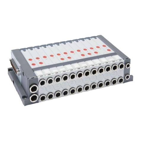
The CPU module allow to control and manage the activation of digital and / or analog outputs
according to the commands received from the ProfiNet external bus and to transmit on the
external bus diagnostic information provided by the system and the digital and/or analog inputs.
The system consists of a CPU module (ProfiNet slave device) that communicates with a ProfiNet
Master via the bus.
On the right side of the CPU module you can connected the input and output modules, analog
and digital, and adapters that allow you to connect integrally the island a few series of valves. In
addition a number of modules that allow you to remotely locate the modules above. For more
details refer to the "Operation and maintenance - Bus System Internal Camozzi" manual.
POWER
L24V P24V PROFINET USB
DRIVER
µC 1024 I/O
LEDS
ROTARY
SWITCHS

Operation and maintenance instructions
CPU PROFINET Series CX06 module
5000004825
Versione 01
35
7. Installation and start-up
During unpacking, take great care not to damage the product.
Check whether there are any fault caused by product transport or storage.
Separate all packaging material to enable the recovery or disposal in accordance with current
standards in the country of use.
Before operating the component, ensure that the stated specifications and performance
correspond to requirements.
During component installation, ensure suitable voltage overload protection devices are
fitted.
During component installation, ensure that no hazards are generated due to mechanical
movements.
Install the component in an area where the set-up and maintenance phases are easily
performed without generating hazards for the operator.
Close off any connections with suitable safety caps/covers.
The components must be fixed correctly using, where possible, the specific anchors and
ensuring that the fixture remains efficient even when the actuator is repeatedly used at a
high frequency and in the presence of strong vibrations.
In the case of strong vibrations envisage suitable devices/systems able to dampen the effect
on the component.
POWER
BUS OUT BUS IN
LEDS

Operation and maintenance instructions
CPU PROFINET Series CX06 module
5000004825
Versione 01
36
Envisage the installation of dehumidifiers to avoid the formation of humidity or
condensation on internal components.
If the device is used to activate an actuator on which any accidental movement can generate
a hazard, envisage suitable locking devices on the mobile section of the actuator.
Ensure that the connectors are correctly connected and secured.
The device can be connected to DIN rails using the relative elements PCF-E520 fitted on the
rear of the body.
The component can be directly fixed to a support using the 8 holes (of which 2 threaded M6)
present on the side of the body

Operation and maintenance instructions
CPU PROFINET Series CX06 module
5000004825
Versione 01
37
This illustrates the pins of the M12 connector located on the upper section CPU module:
POWER Connector M12A 5 poles male
Pin
Signal Description
1 L24V 24Vdc power supply (logic, digital input, analog I/O): connect to the
positive pole of the 24Vdc power supply (ref. GND).
2 P24V 24Vdc power supply (digital output): connect to the positive pole of the
24Vdc power supply (ref. GND).
3 GND Common (reference pin 1 and 2): connect to the negative pole of the
24Vdc power supply (compulsory).
4 EARTH Earth connection
5 NC Not connected
BUS IN Connector M12D 4 poles Female
Pin
Signal Description
1 TD+ Transmit data +
2 RD+ Receive data +
3 TD- Transmit data -
4 RD- Receive data -
BUS OUT Connector M12D 4 poles Female
Pin
Signal Description
1 TD+ Transmit data +
2 RD+ Receive data +
3 TD- Transmit data -
4 RD- Receive data -
For electrical connection are available the following wired connectors.
CONNECTOR CODE DESCRPTION
POWER CS-LF04HB Power supply straight connector
CS-LR04HB Power supply angled connector
BUS IN
BUS OUT
CS-SM04H0 Bus-In and Bus-OUT straight M12 male connector
CS-SB04HB-D100
CS-SB04HB-D500
CS-SB04HB-DA00
Straight moulded cable
CS-SC04HB-D100
CS-SC04HB-D500
CS-SC04HB-DA00
Angled moulded cable

Operation and maintenance instructions
CPU PROFINET Series CX06 module
5000004825
Versione 01
38
Use only power able to ensure a reliable electrical isolation of the supply voltage according
to IEC 742 / EN 60742 / VDE 0551 with a minimum strength of 4 kV isolation Protected Extra
Low Voltage, PELV.
The user must take the necessary measures to prevent damage to the system caused by non-
periodic overvoltage spikes on the power lines produced by power break to high-energy
equipment.
The voltage interruptions are permitted according to the severity level PS2.
About electromagnetic compatibility, the CPU module is designed to work in area A.
The board implements a protection against inversion of polarity on the power supply
voltage.
The power supply voltage must be within the range of 24V±10%.
The rated voltage of the CPU module is 24 VDC -15% / + 20% (as indicated by the Standard
IEC 61131-2). If the loads connected to the initial node may require severest tolerances of
the value of the supply voltage, the power supply voltage must comply with these. If the
inputs connected to the initial node may require in the severest tolerances of the value of
the supply voltage, the logic supply voltage of the node must comply with these.
For example, if you connect the valves HN Series, the tolerance of the power supply voltage
must be ± 10%. If you connect the CSH sensors with power supply 10-30V (-58% / + 25%),
the tolerance of the logic supply voltage is -15% / + 20%.
For the system it is mandatory to connect the logic voltage (pin 1), otherwise the initial
module remains off.
For the correct operation of the system is mandatory to connect to the initial module the
logic voltage (pin 1), the power voltage (pin 2), the reference to 0 V (GND, pin 3) and the
earth.
On supply cables of a valve group, it produces a voltage drop that dependent by load. This
can create that the supply voltage (logic and power) does not fall within the allowable
tolerance. If the sections of the cables for the power supply and for the logic power supply
are the same, it is possible to apply the following formula in order to calculate the length. To
limit the effects of induced noises, it is recommended to limit the length of the power cable
to 3 mt.
Before is necessary to calculate:
o The maximum current value for Logic+Input (I1) and for Power (I2)
o The minimum power supply value expected during operation (Vmin), whereas it
depends on the load connected and that the mains voltage can have oscillations.
Use the value below in the following formula explained by the electrical drawing.

Operation and maintenance instructions
CPU PROFINET Series CX06 module
5000004825
Versione 01
39
o Il = Logic currente + SPI input current
o Ip = Power current (loads)
o Rc1 + Rc2 = Cable resistance
o Rc0 = Common cable resistance
o L = Cable length
In order to calculate the cable length use this formula:
Where:
o Vp min: minimum tension necessary for output
o V min: minimum tension expected from power supply
o Il: corrent necessary for logic and sensor
o Ip: corrent necessary for output
o S: cable section
o K: cable conductance (copper conductance Kcu = 56 m/(mm² * Ω))
Example:
V min = 24 V
Vp min = 21.6 V
Il = 1 A
Ip = 1 A (40 Series H coils)
S = 0,75 mm²
Kcu = 56 m/(mm² * Ω)

Operation and maintenance instructions
CPU PROFINET Series CX06 module
5000004825
Versione 01
40
To improve immunity to disturbance and prevent damage, it is recommended to connect
the device to the circuit earthing system using any one of the holes on the aluminium body.
In order to connect the CPU module to ProfiNet bus, is reccomended to use a CAT5 complies
with specification.
The ProfiNet segment maximum length is 100 mt. If it is necessary to exceed the maximum
lengths indicated below, you must to use repeater.
For configuration of the CPU module and the connected modules, download the set-up file
of the software CX-Configurator from the web site http://www.camozzi.com and proceed
with installation according to the instructions on screen displayed during the process. For
more details, please refer to the "Operating and Maintenance Instructions - CX
Configurator".
In order to configure the CX06 CPU module with a programmer/PC it is necessary to use the
archive GSDML-V2.31-Camozzi-CX-20160111.xml. In addition to the slave characteristic data
(ID Number, revision, etc.), the GSDML file contains the identifiers of the modules that are
used for the hardware configuration of the PLC. The GSDML file of the CPU module can be
downloaded from the website Camozzi.
On the GSDML file, the following modules are descripted. Use these modules on the
programmer/PC in order to realize the CPU module HW configuration.
Module description Input bytes used on the PLC memory Output bytes used on the PLC
memory
1 Byte In 1 0
1 Byte Out 0 1
2 Byte In 2 0
2 Byte Out 0 2
4 Byte In 4 0
4 Byte Out 0 4
8 Byte In 8 0
8 Byte Out 0 8
16 Byte In 16 0
16 Byte Out 0 16
32 Byte In 32 0
32 Byte Out 0 32

Operation and maintenance instructions
CPU PROFINET Series CX06 module
5000004825
Versione 01
41
64 Byte In 64 0
64 Byte Out 0 64
128 Byte In 128 0
128 Byte Out 0 128
The CPU module CX06 is compatible with isochronous networks (IRT) Class 3. The
management of I / O is not isochronous.
The following steps describes some example about HW configuration realized with TIA portal
software. It is assumed knowledge of the topics covered in the TIA software manuals.
Used configurator: HW Configurator TIA Portal Version 13 SP1
In order to import the GSDML file and icons on TIA Portal configurator, refer to the following
steps:

Operation and maintenance instructions
CPU PROFINET Series CX06 module
5000004825
Versione 01
42

Operation and maintenance instructions
CPU PROFINET Series CX06 module
5000004825
Versione 01
43

Operation and maintenance instructions
CPU PROFINET Series CX06 module
5000004825
Versione 01
44

Operation and maintenance instructions
CPU PROFINET Series CX06 module
5000004825
Versione 01
45

Operation and maintenance instructions
CPU PROFINET Series CX06 module
5000004825
Versione 01
46
When the procedure is completed, the slave node CX06 will be available with all its modules
in the catalog of the HW configurator, on the folder: “Ulteriori apparecchiature da campo\
PROFINET IO\I/O\CAMOZZI SPA\Camozzi Spa\Serie CX\CX06 PNS Adapter.
The slave node CX06 can be dragged around the window that displays the network.

Operation and maintenance instructions
CPU PROFINET Series CX06 module
5000004825
Versione 01
47
With a double click on the object you access to its properties and on the right side of the
screen are displayed the modules that are used to configure the node. The various input and
output modules can be dragged in the appropriate section until forming the desired data
size. There are no specific limitations on the order in which the modules are placed in the
configuration. The only constraint to be respected is the maximum number of bytes: 128 for
inputs and outputs. The user must calculate the minimum size of the data necessary for the
functioning of CX06 node and the modules connected to it. The information regarding the
size of the data occupied by the individual modules and their meaning (correspondence
between bits and input / physical output) are contained in the manual "Operating and
Maintenance Instructions - Bus System Internal Camozzi".
Furthermore the CX-Configurator software calculates automatically the size of the data used
by the CX06 node and by the modules connected to it. For more details on using the
configurator and in particular of this feature, refer to the manual "Operating and
Maintenance Instructions - CX Configurator".
The PLC recognizes the different nodes connected to the network through the node name
and then assigns them all the necessary parameters to the Ethernet communication
(address, gateway, and subnet mask). The default values of these parameters are as follows:
Name: empty
IP Address: 0.0.0.0
Gateway: 0.0.0.0
Subnet mask: 255.255.255.0

Operation and maintenance instructions
CPU PROFINET Series CX06 module
5000004825
Versione 01
48
By default in the CPU module there isn’t any name so it’s necessary set its to start the
communication.
Is possible to change the node name within the TIA Portal Configurator using the following
procedure.
Table of contents
Other Camozzi Control Unit manuals
Popular Control Unit manuals by other brands

EOS
EOS Infratec Classic Assembly and operating instruction

Danfoss
Danfoss SVA-S 15-200 Series instructions

Trane
Trane Tracer MP503 Installation and operation

Rockwell Automation
Rockwell Automation SILVER Technology HARRY HI 1734-WS Installation & operation manual

resideo
resideo Braukmann BA295D-3/4WH installation instructions

CSM
CSM HV BM 1.1 installation manual

CALEFFI
CALEFFI SinkMixer 521201A Installation and commissioning manual

Anslut
Anslut 402389 operating instructions

Bender
Bender RCMA126P1-S operating manual

Pilz
Pilz PSEN ma1.4n-51 operating manual

Advanced Micro Controls Inc.
Advanced Micro Controls Inc. 1700 Series user manual

Siemens
Siemens SINUMERIK 808D Programming and operating manual