Health Zenith 5910 User manual

© 2009 HeathCo LLC 598-1378-00
Model 5910
Motion Sensor Light
Control
TEST
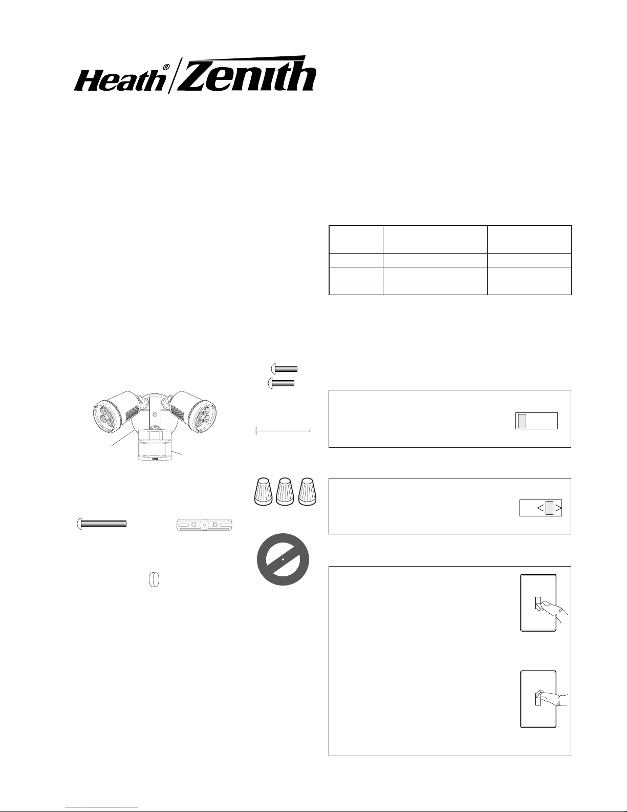
Features
• EnergyefcientLEDlightsource.
• Turnsonlightingwhenmotionisdetected.
• Automaticallyturnslightingoff.
• Photocellkeepsthelightingoffduringdaylighthours.
• LEDindicatesmotionwassensed(dayornight).
TEST 1 5 10
ON-TIME
Put the ON-TIME switch on the
bottomofthesensorintheTEST
position.
OPERATION
*resetstoAutoModeatdawn.
ON-TIME
TEST 1 5 10
...backon.
1Second
OFF then...
PuttheON-TIMEswitchinthe1,5,
or10minuteposition.
Manual mode only works at night
becausedaylightreturnsthesensor
toAUTO.
Flipthelightswitchoffforonesecond
thenbackontotogglebetweenAUTO
andMANUALMODE.
Manual mode works only with the
ON-TIME switch in the 1, 5, or 10
position.
Note:Whenrstturnedonwaitabout11/2minutesfor
thecircuitrytocalibrate.
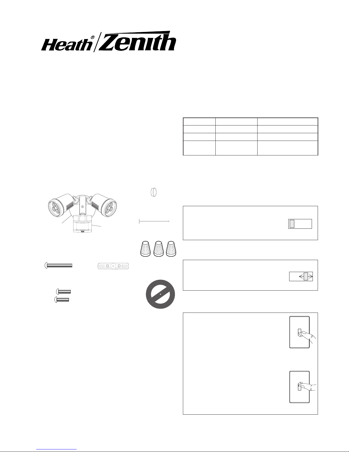
Thispackageincludes:
LightControl
Sensor
Cover
Plate
Requirements
• Thelightcontrolrequires120-voltsAC.
• IfyouwanttouseManualMode,thecontrolmustbe
wiredthroughaswitch.
• Some codes require installation by a
qualified electrician.
• Thisproductisintendedforusewiththeenclosed
gasketandwithajunctionboxmarkedforuseinwet
locations.
Mode: On-Time Works: Day Night
Test 5Seconds x x
Auto 1,5,or10Minutes x
Manual ToDawn* x
AUTO
MANUAL MODE
PlasticHanger
RubberPlug
Gasket
6Screws
(3sizesincluded)
MountingStrap
MountingBolt
3Wire
Connectors
2598-1378-00
INSTALLATION
Foreasyinstallation,selectanexistinglightwithawall
switchforreplacement.IMPORTANT:DoNOTusewith
dimmersortimers.
Forbestperformance,mountthextureabout8ft.(2.4m)
abovetheground.
NOTE:
Ifxtureismountedhigherthan
8ft.(2.4m),aimingthesensordownwillreducecoverage
distance.
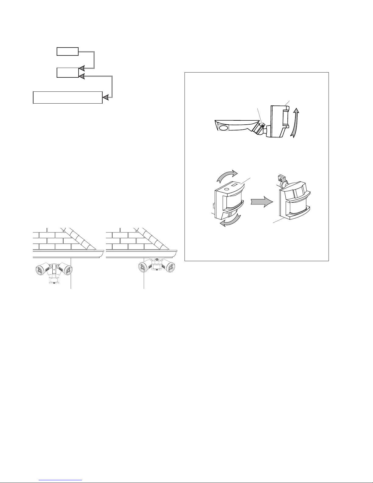
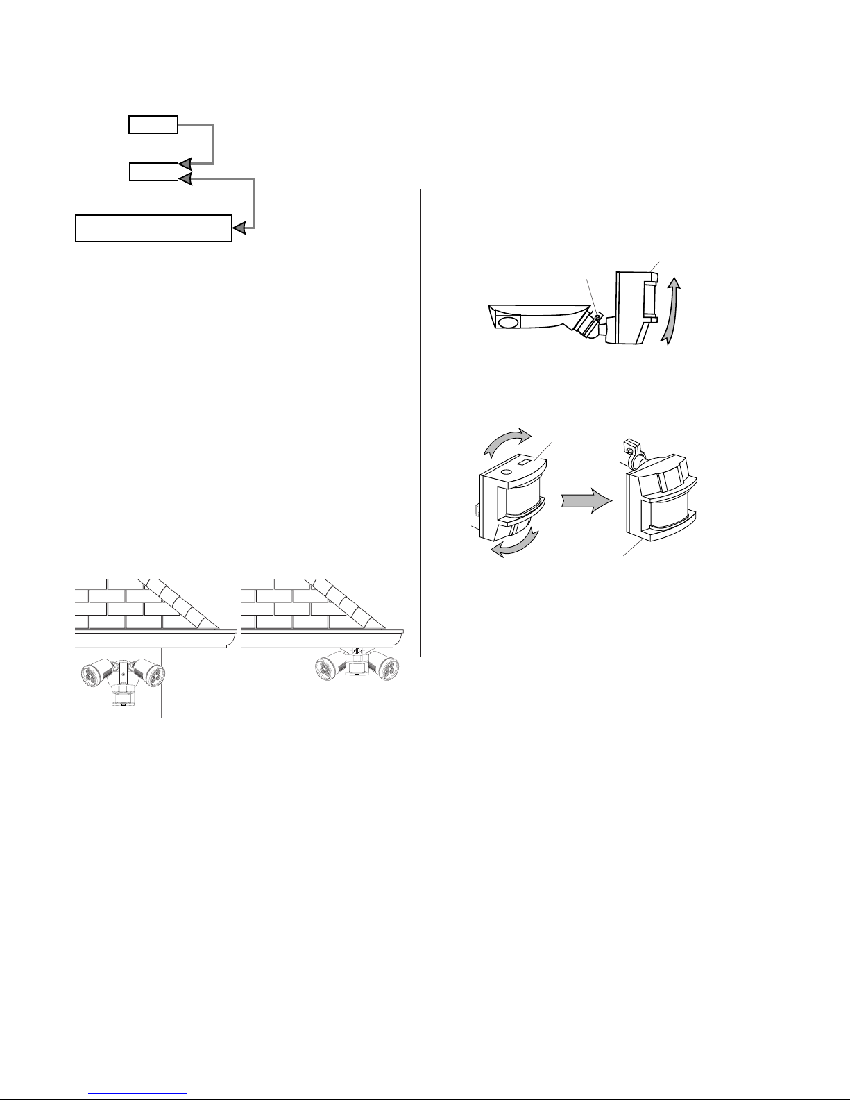
Foreavemountonly:
❒Swingthesensorheadtowardstheclampscrew
joint.
If the sensor pops out of the ball joint, loosen the
clampscrewandpushthesensorbackintotheball
joint.Tightentheclampscrewwhendone.
❒Thenrotatethesensorheadclockwise180°sothe
controlsfacedown.
Controls
Wall Mount Eave Mount
For under eave installation, the sensor head must
be rotatedasshowninthenexttwostepsforproper
operationandtoavoidtheriskofelectricalshock.
Controls
Controls
ClampScrew
Move ON-TIME Switch to
1, 5, or 10 minutes
Mode Switching Summary
Flip light switch off
for one second then
back on*
MANUAL MODE
AUTO
TEST
* Ifyougetconfusedwhileswitchingmodes,turnthe
poweroffforoneminute,thenbackon.Afterthecali-
brationtimethecontrolwillbeintheAUTOmode.
NOTE: Lightxtureandsensorshouldbemountedas
shownabovewheninstalled(dependingupontypeof
installation).
3
598-1378-00
1. Removetheexistinglightxture.
2. Installthemountingstrapasshownusingtwoscrews
thattyourjunctionbox.
3. Theplastichangercanbeusedtoholdthexture
whilewiring.Thesmallendoftheplastichanger
canbethreadedthroughtheholeinthecenterof
thecoverplate.Thesmallendthengoesintoone
oftheslotsonthemountingstrap.
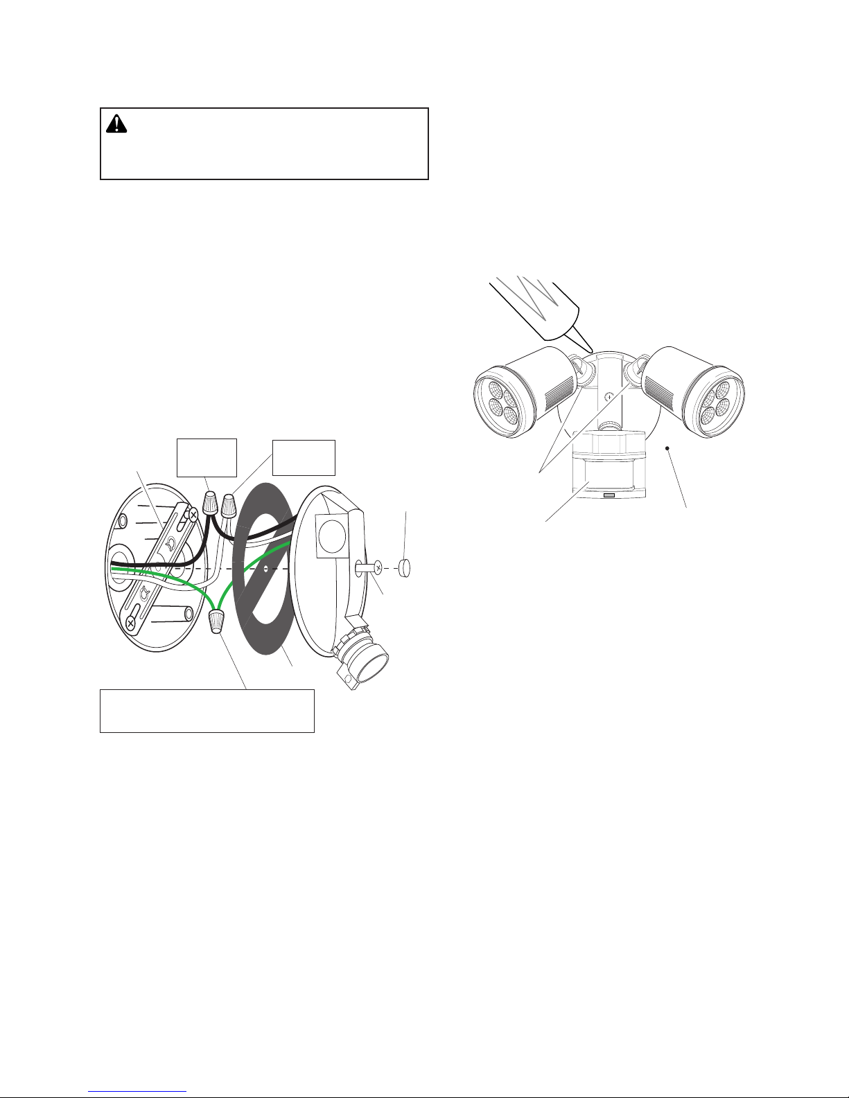
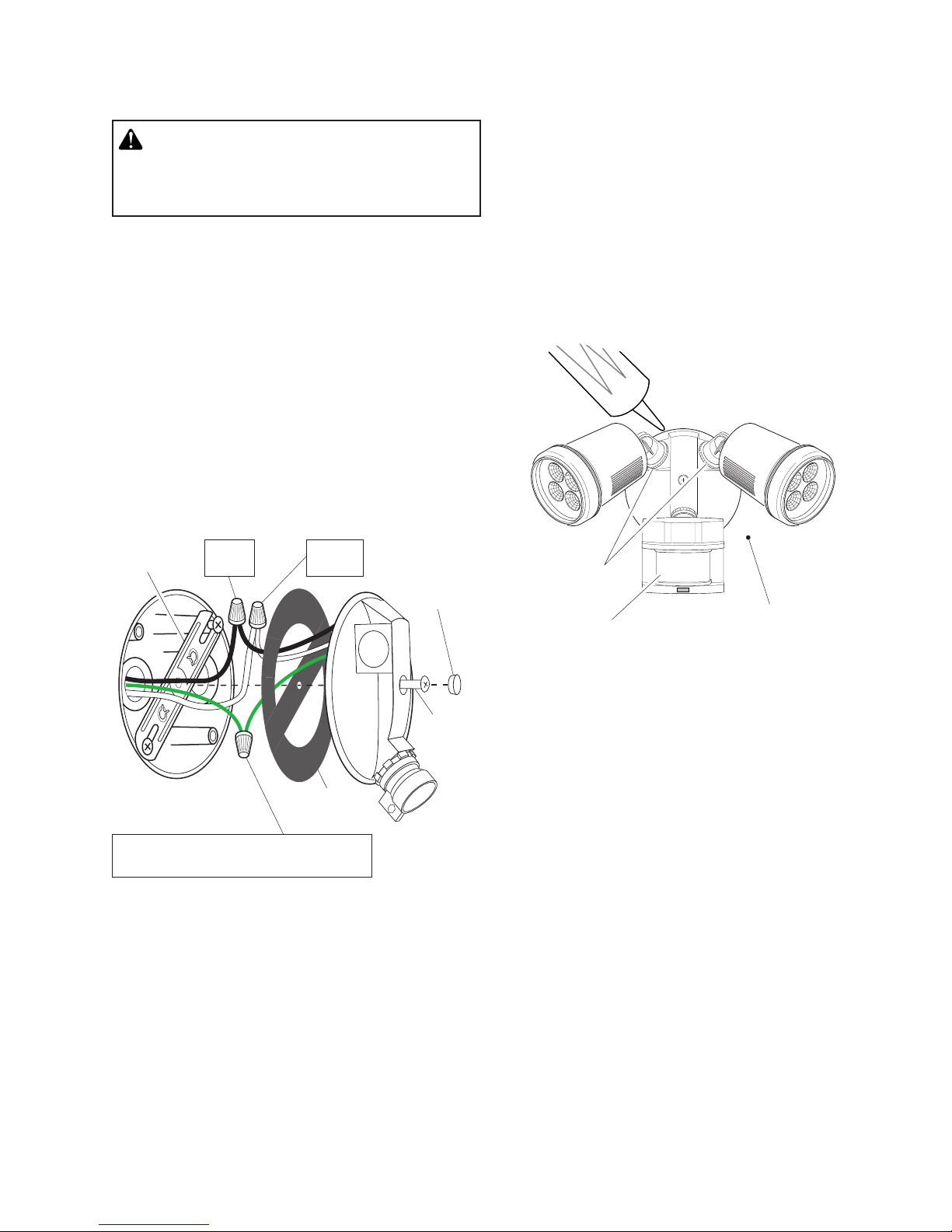
4. Route the light control’s wires through the large
gasketholes.
5. Twistthejunctionboxwiresandxturewirestogether
asshown.Securewithwireconnectors.
White to
White
Black to
Black
Junction box ground wire to
green ground wire on fixture.
Gasket
Mounting
Strap
Mounting
Bolt
Rubber
Plug
Mount the Light Control
1. Alignthelightcontrolcoverplateandcoverplate
gasket.Securewiththemountingbolt.
2. Pushtherubberplugrmlyintoplace.
3. Ifawetlocationjunctionboxwasnotused,caulk
the wall plate mounting surface with silicone
weathersealant.
4. Adjustthelampheadsbylooseningthelocknuts
butdonotrotatethelampheadsmorethan180°
fromthefactorysetting.
LockNut
Keeplampheadsatleast1"
(25mm)fromthesensor.Do
notallowthelampheadsto
blockthelens.
Wire the Light Control
WARNING:Turn power off at circuit breaker or
fuse. Place tape over circuit breaker switch and
verify power is off at the fixture.
Lens

4598-1378-00
180°
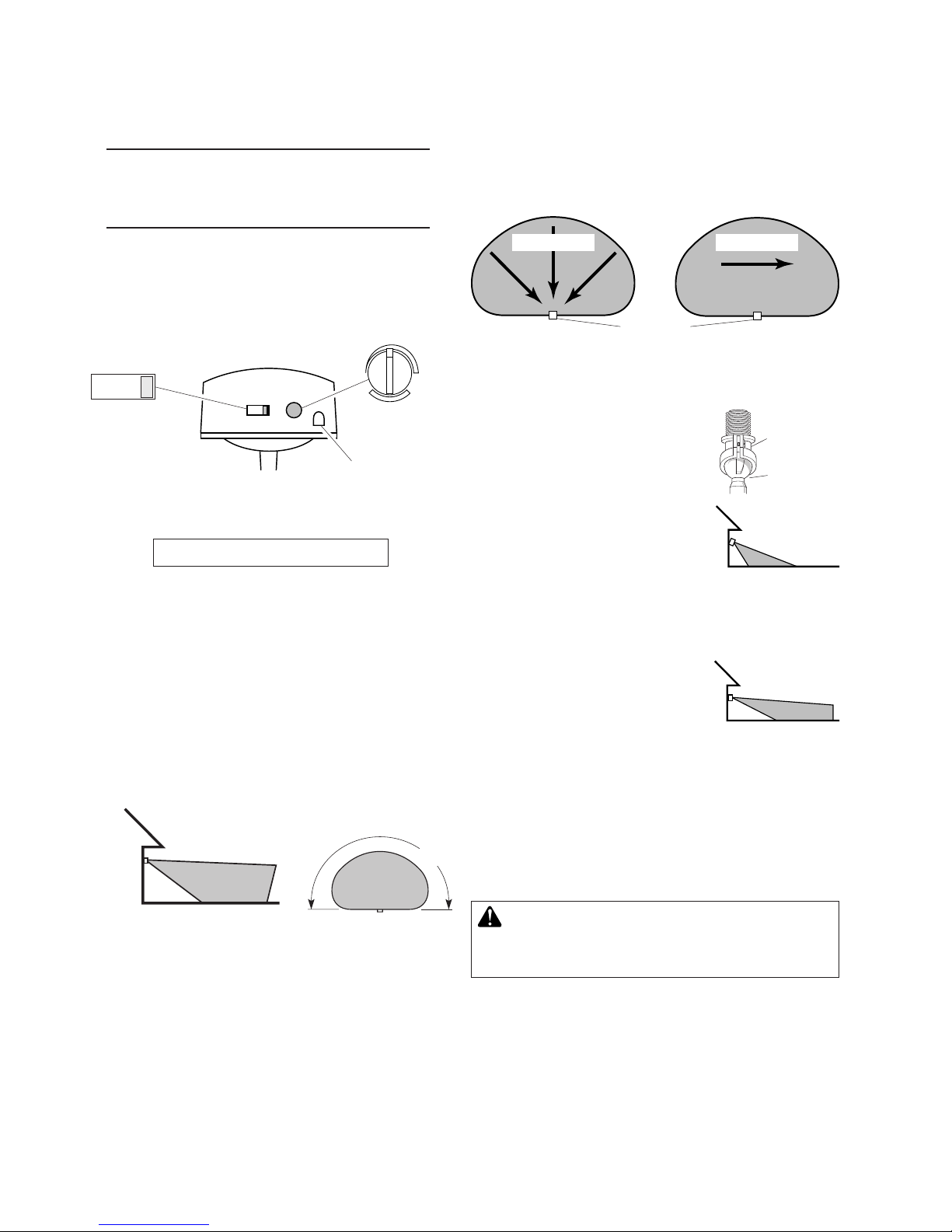
70ft.
(21m)
8ft.
(2.4m)
Maximum Range Maximum
Coverage Angle
NOTE:Ifxtureismountedhigherthan8ft.(2.4m),aim-
ingthesensordownwillreducecoveragedistance.
Thedetectorislesssensitivetomotiondirectlytowardsit.
3. Loosentheclampscrewinthe
sensor ball joint and gently
rotatethesensor.
4. Walk through the coverage
area noting where you are
whenthelightsturnon(also,
theLEDwillashseveraltimes
whenmotionisdetected).Move
thesensorheadup,down,or
sidewaystochangethecover-
agearea.Keep the sensor at
least 1" (25 mm) away from
the bulbs.
5. AdjusttheRANGEasneeded.
RANGE set too high may
increasefalsetriggering.
6. Secure the sensor head by
tightening the clamp screw.
Donotovertightenthescrew.
7. SettheamountofON-TIMEyouwantthelightstostay
onaftermotionisdetected(1,5,or10minutes).
Bottom of Sensor
Avoid aiming the control at:
•Objects that change temperature rapidly, such as
heating vents and air conditioners.These heat
sourcescouldcausefalsetriggering.
•Areaswherepets or trafficmaytriggerthecontrol.
•Nearby large, light-colored objectsreectinglight
maytriggertheshut-offfeature.Donotpointother
lightsatthesensor.
Clamp
Screw
Ball
Joint
Aim Sensor
Down for Short
Coverage
Aim Sensor
Higher for Long
Coverage
Least Sensitive Most Sensitive
WARNING: Risk of fire. Do not aim the lamp
heads at a combustible surface within 3 ft. (1 m).
TEST AND ADJUSTMENT
1. Turn on the circuit breaker and light switch.
NOTE: Sensor has a 1 1/2 minute warm up period
beforeitwilldetectmotion.Whenrstturned
on,wait11/2minutes.
2. Turn the RANGE control to the medium position
(halfwaybetweenMINandMAX)andtheON-TIME
controltotheTESTposition.
Motion Motion
Sensor
Photocell
RANGE
1051TEST
ON-TIME
MIN MAX

5
598-1378-00
SYMPTOM POSSIBLE CAUSE SOLUTION
Lights will not come
on.
1. Lightswitchisturnedoff.
2. Fuseisblownorcircuitbreakeristurnedoff.
3. Daylightturn-offisineffect.
4. Incorrectcircuitwiring,ifthisisanewinstallation.
5. Lightcontrolaimedinwrongdirection.
1. Turnlightswitchon.
2. Replacefuseorturncircuitbreakeron.
3. Recheckafterdark.
4. Verifywiringiscorrect.
5. Re-aimlightcontroltocoverdesiredarea.
Lightscomeoninday-
light.
1. Light control may be installed in a relatively dark
location.
2. LightcontrolisinTEST.
1. Thextureisoperatingnormallyunderthesecondi-
tions.
2. Setcontrolswitchto1,5,or10minutes.
Lights come on for no
apparentreason.
1. Lightcontrolmaybesensingsmallanimalsorauto-
mobiletrafc.
2. Rangeissettoohigh.
1. Re-aimlightcontrol.
2. Reducerange.
Lightsstayoncontinu-
ously.
1. Alampheadispositionedtooclosetothelightcontrol
orpointedatnearbyobjectsthatcauseheattotrigger
thelightcontrol.
2. Thelightcontrolmaybepickingupaheatsource
likeanairvent,dryervent,orbrightlypainted,heat-
reectivesurface.
3. Lightcontrolisinmanualmode.
1. Repositionthelampheadawayfromthelightcontrol
ornearbyobjects.
2. Reducerange.
3. SwitchlightcontroltoAUTO.
Lightsashonandoff. 1. Heatorlightfromthelampheadsmaybeturning
thelightcontrolonandoff.
2. Heatbeingreectedfromotherobjectsmaybeturn-
ingthelightcontrolonandoff.
3. LightcontrolisintheTESTmodeandwarmingup.
1. Repositionthelampheadawayfromthelightcon-
trol.
2. Repositionlightcontrol.
3. Flashingisnormalundertheseconditions.
Lightsashonce,then
stay off in manual
mode.
Lightcontrolisdetectingitsownlights. Reposition lamp heads to keep area below the light
controlrelativelydark.
SPECIFICATIONS
Range............Upto70ft.(21m)[varieswith
surroundingtemperature].
SensingAngle......Upto180°
ElectricalLoad......150Milliamps;12Watts(Typi-
cal)
PowerRequirements.120VAC,60Hz
TROUBLESHOOTING GUIDE
OperatingModes....TEST, AUTO, and MANUAL
MODE
TimeDelay ........1,5,10minutes
Range............Adjustable
HeathCoLLCreservestherighttodiscontinueprod-
uctsandtochangespecicationsatanytimewithout
incurringanyobligationtoincorporatenewfeatures
inproductspreviouslysold.

6598-1378-00
THREE YEAR LIMITED WARRANTY
Thisisa“LimitedWarranty”whichgivesyouspeciclegalrights.Youmayalsohaveotherrightswhichvary
fromstatetostateorprovincetoprovince.
Foraperiodofthreeyearsfromthedateofpurchase,anymalfunctioncausedbyfactorydefectivepartsor
workmanshipwillbecorrectedatnochargetoyou.
Not Covered -Repairservice,adjustmentandcalibrationduetomisuse,abuseornegligence,lightbulbs,
batteries,andotherexpendableitemsarenotcoveredbythiswarranty.Unauthorizedserviceormodica-
tionoftheproductorofanyfurnishedcomponentwillvoidthiswarrantyinitsentirety.Thiswarrantydoes
notincludereimbursementforinconvenience,installation,setuptime,lossofuse,unauthorizedservice,or
returnshippingcharges.
ThiswarrantycoversonlyHeathCoLLCassembledproductsandisnotextendedtootherequipmentand
componentsthatacustomerusesinconjunctionwithourproducts.
THISWARRANTY IS EXPRESSLYINLIEUOFALLOTHERWARRANTIES,EXPRESSORIMPLIED,
INCLUDINGANYWARRANTY,REPRESENTATIONORCONDITIONOFMERCHANTABILITYORTHAT
THEPRODUCTSAREFITFORANYPARTICULARPURPOSEORUSE,ANDSPECIFICALLYINLIEU
OFALLSPECIAL,INDIRECT,INCIDENTAL,ORCONSEQUENTIALDAMAGES.
REPAIRORREPLACEMENTSHALLBETHESOLEREMEDYOFTHECUSTOMERANDTHERESHALL
BENOLIABILITYONTHEPARTOFHEATHCOLLCFORANYSPECIAL,INDIRECT,INCIDENTAL,OR
CONSEQUENTIALDAMAGES,INCLUDINGBUTNOTLIMITEDTOANYLOSSOFBUSINESSORPROF-
ITS,WHETHERORNOTFORESEEABLE.Somestatesorprovincesdonotallowtheexclusionorlimitation
ofincidentalorconsequentialdamages,sotheabovelimitationorexclusionmaynotapplytoyou.
Please keep your dated sales receipt, it is required for all warranty requests.
TECHNICAL SERVICE
Please call 1-800-858-8501 (English speaking only) for assistance before returning
product to store.
Ifyouexperienceaproblem,followthisguide.YoumayalsowanttovisitourWebsiteat:www.hzsupport.com.
Iftheproblempersists,call*forassistanceat1-800-858-8501(Englishspeakingonly),7:30AMto4:30PMCST
(M-F).Youmayalsowrite*to:
HeathCoLLC,P.O.Box90045
BowlingGreen,KY42102-9045
ATTN:TechnicalService
*IfcontactingTechnicalService,pleasehavethefollowinginformationavailable:ModelNumber,DateofPur-
chase,andPlaceofPurchase.
No Service Parts Available for this Product
Please keep your dated sales receipt, it is required for all warranty requests.
7
598-1378-00
©2009HeathCoLLC 598-1378-00S
FUNCIONAMIENTO
Modelo 5910
Control de luz del
detector de movimiento
Para PRUEBA:
Características
• FuentedeluzDELdeenergíaeciente.
• Prendelaluzcuandodetectamovimiento.
• Apagalaluzautomáticamente.
• Lafotocélulamantienelaluzapagadaduranteeldía.
• LEDindicaquesehadetectadomovimiento(durante
eldíaolanoche).
TEST 1 5 10
ON-TIME
Pongaelinterruptordetiempo(ON-
TIME),alfondodeldetector,enla
posicióndeprueba(TEST).
*SeponeenAutomáticoalamanecer.
ON-TIME
TEST 1 5 10
...préndalo.
1segundo
APAGADO
luego...
Ponga el interruptor de tiempo
(ON-TIME) en la posición de
1,5o10minutos.
Elmodomanualfuncionasóloporla
nocheporquelaluzdeldíaponeal
detectorenmodoAUTOMÁTICO.
Apagueelinterruptorporunsegundo
yvuélvaloaprender para conmu-
tar entre MODO AUTOMÁTICO y
MANUAL.
Elmodomanualfuncionasóloconel
interruptorON-TIMEenlaposición
1,5o10.
Nota:Cuandoloprendaporprimeravezespere11/2
minutosparaqueelcircuitosecalibre.
Estepaquetetiene:
Controldeluz
Detector
Placa
cubertora Colgadorplástico
Enchufede
caucho
Empaque
6tornillos
(3dimensiones)
Láminademontaje
1perno
3conectores
dealambre
Requisitos
• Elcontroldeluzrequiere120VCA.
• ParausarelSobrecontrolManual,conecteelcontrol
conuninterruptor.
• Algunos códigos requieren instalación por un
electricista calificado.
• Serecomiendausaresteproductoconelempaque
provistoyconunacajadeempalmemarcadapara
usoenlugareshúmedos.
Para AUTOMÁTICO:
Para MODO MANUAL:
Modalidad: Atiempo:
Trabaja:
Día Noche
Prueba 5seg. x x
Autom. 1,5,o10min. x
Manual Hastael
amanecer*
x

8598-1378-00
Mueva el interruptor de
tiempo (ON-TIME) a 1, 5
o 10 minutos
Resumen de las modalidades del interruptor
Apague el interruptor
por un segundo y
préndalo de nuevo*
PRUEBA
AUTOM.
MODO
MANUAL
* Siseconfundemientrascambiadefases,apague
laelectricidadporunminutoypréndaladenuevo.
Despuésdeltiempodecalibraciónelcontrolestará
enfaseAUTO(MÁTICA).
INSTALACIÓN
Sóloparamontajeeléctrico:
❒Girelacabezadeldetectorhacialaunióndeltornillo
sujetador.
Sieldetectorsesaledelauniónesférica,aojeel
tornillosujetadoryempujeeldetectorhaciadentro
de la unión esférica. Apriete el tornillo sujetador
cuandotermine.
❒Entonces gire la cabeza del detector hacia la
derechapor180°hastaqueloscontrolesmiren
haciaabajo.
Controles
Montaje en pared Montaje en alero
Para instalarlo bajo el alero, la cabeza del detector
debe ser giradacomosemuestraenlosdospasos
siguientesparaevitarelriesgodeunchoqueeléctrico.
Controles
Controles
TornilloSujetador
Para una fácil instalación escoja una luz con un
interruptor de pared. IMPORTANTE: No lo use con
temporizadoresoatenuadoresdeluz.
Paraunmejorfuncionamiento,instaleelaparatoacasi
2.4mdelsuelo.
NOTA:Sielaparatoestáinstaladoa
másde8pies(2,4m),siseapuntaeldetectorhacia
abajosereduciráladistanciadecobertura.
NOTA:Lalámparayelsensordebemontarsecomo
seindicaarriba,unavezinstalado(segúneltipode
instalación).

9
598-1378-00
Blanco a
Blanco
Negro a
Negro
Empaquetadura
láminade
Montaje
Pernode
Montaje
Enchufe
deCaucho
1. Quiteelaparatodeluzexistente.
2. Instalelaláminademontajealacajadeempalme
usandotornillosapropiadosparalacajadeempal-
me.
3. Sepuedeusarelcolgadorplásticoparasostenerel
aparatomientrasseinstalaelcableado.Elextremo
pequeñodelcolgadorsepuedepasarporelagujero
enelcentrodelaplacacubertora.Elextremope-
queñovaluegodentrodelasranurasdelalámina
demontaje.
4. Pasetodosloscablesdelaparatoporlosagujeros
grandesdelempaque,comosemuestra.
5. Conecte los cables de la caja de empalme con
loscablesdelaparatodeluz, comosemuestra.
Tuérazalosjuntosyasegúrelosconunconectorde
cables.
Conecte el Control de Luz Instale el Control de Luz
1. Pongaelpernodemontajeatravésdelfrentedelatapa
delacajadeempalme.Empujeelagujeropequeñode
laempaquetadurasobreeltornillodemontaje.
2. Empujeeltapóndecauchormementehastaque
encaje.
3. Si no se usó una caja de empalme en un lugar
húmedo,calafateelasuperciedemontajedela
placadelaparedconunselladordesiliconacontra
laintemperie.
4. Acomode los cabezales de la lámpara aojando
lascontratuercasperonogireloscabezalesdela
lámparamásde180°desuconguraciónhecha
enfábrica.
Contratuercas
Placatranslúcida
ADVERTENCIA: Desconecte la energía en el
fusible o cortacircuitos. Coloque cinta encima
del interruptor de cortacircuitos y verifique que
la energía está apagada en la luminaria.
Alambre de conexión a tierra de la caja de em-
palme al alambre verde de conexión a tierra del
aparato.
Mantengaloscabezalesdela
lámparaporlomenosa1"(25
mm)deldetector.Nodejeque
loscabezalesdelalámpara
bloqueenlaplacadifusora.
10 598-1378-00
NOTA:Sielaparatoestáinstaladoamásde8pies(2,4
m),siseapuntaeldetectorhaciaabajosereducirála
distanciadecobertura.
Eldetectoresmenossensibledelmovimientoquese
dirigehaciaél.
3. Aojeeltornillosujetadorenla
uniónesféricaygiredespacio
eldetector.
4. Camine por el área a prote-
gerse y dése cuenta dónde
estácuandoseprendelaluz.
Muevalacabezadeldetector
hacia arriba, hacia abajo o
hacia los lados para cam-
biar el área de protección.
Mantenga al detector por
lomenosa1pulgada(25mm)
de las lámparas.
5. Fije la sensibilidad (RANGE)
como necesite. Demasiada
sensibilidad puede aumentar
lasfalsasalarmas.
6. Asegure la puntería de la ca-
beza del detector ajustando
el tornillo sujetador. No lo
aprietedemasiado.
7. Fijeelperíododetiempo(ON-TIME)quelaluzdebe
quedarseprendidadespuésdedetectarmovimiento
(1,5o10minutos).
Parte de abajo del detector
Evite apuntar el control hacia:
•Objetosquecambienrápidamentedetemperatura
talescomoductos de calefacción y acondiciona-
dores de aire.Estasfuentesdecalorpuedencausar
falsasalarmas.
•Áreas donde animales domésticos o el tráfico
puedanactivarelcontrol.
•Los objetos grandes cercanos y de colores res-
plandecientes que reejan la luz del día pueden
hacerqueeldetectorseapague.Noapunteotras
luceshaciaeldetector.
Lo menos sensible Lo más sensible
ADVERTENCIA:Riesgodeincendio.Noapunte
los cabezales de la lámpara hacia una superficie
combustible que esté dentro de 3 pies (1 m).
Alcance Máximo Angulo de
Cobertura Máxima
8pies
(2,4m)
PRUEBA Y AJUSTE
1. Prenda el cortacircuitos y el interruptor de luz.
NOTA: Eldetectortieneunperíododecercade11/2
minutosdecalentamientoantesdedetectar
movimiento. Cuando lo prenda por primera
vez,espere11/2minutos.
2. GireelcontroldeALCANCE(RANGE)alaposición
media(entreMINyMAX)yelcontroldeDURACIÓN
(ON-TIME)alaposicióndePRUEBA(TEST).
RANGE
1051TEST
ON-TIME
MIN MAX
70pies
(21m)
180°
Detector
Movimiento Movimiento
Tornillo
Sujetador
Unión
Esférica
Apunte el
detector hacia
abajo para poca
cobertura
Apunte el
detector más
arriba para
mayor cobertura
Fotocélula

11
598-1378-00
SÍNTOMA POSIBLE CAUSA SOLUCIÓN
Laluznoseenciende. 1. Elinterruptordeluzestáapagado.
2. El fusible está quemado o el cortacircuitos está
apagado.
3. Ladesconexióndeluzdeldíaestáenefecto.
4. Alambradoincorrecto,siéstaesunanuevainstala-
ción.
5. Elcontroldeluzestáapuntandoendireccióninco-
rrecta.
1. Enciendaelinterruptordeluz.
2. Cambieelfusibleenciendaeldisyuntor.
3. Compruébelocuandocomiencelaobscuridad.
4. Veriquequeelcableadoestécorrecto.
5. Vuelvaaapuntarelcontroldeluzparaquecubrael
áreadeseada.
Laluzseprendedurante
eldía.
1. Elcontroldeluzpuedeestarinstaladoenunlugar
relativamenteoscuro.
2. ElcontroldeluzestáenfasedePrueba.
1. Elaparatoestáfuncionandonormalmentebajoestas
condiciones.
2. Fijeelinterruptordecontrola1,5o10minutos.
La luz se prende sin
ninguna razón apa-
rente.
1. Elcontroldeluzpuedeestardetectandoanimales
pequeñosoeltrásitodeautomóviles.
2. Elmargenestápuestomuyalto.
1. Reapunteelcontroldeluz.
2. ApagueelAumentodeDistancia.
Laluzsequedaprendida
continuamente.
1. Elfaroestámuycercadelcontroldeluzoapuntando
aobjetoscercanosquegenerancaloryactivanel
controldeluz.
2. El control de luz está apuntando hacia una fuente
decalortalcomounconductodeaire,desecadorao
haciaunasupercieconpinturabrillanteyquereeja
elcalor.
3. Elcontroldeluzestáenelmodomanual.
1. Reubiqueelfarolejosdelcontroldeluzodeobjetos
cercanos.
2. ApagueelAumentodeDistancia.
3. CambieelcontroldeluzaAUTO.
La luz se prende y se
apaga.
1. Elcalorolaluzdelosfarospuedeestarencendiendo
yapagandoelcontroldeluz.
2. El calor reejado por otros objetos puede estar
encendiendoyapagandoelcontroldeluz.
3. ElcontroldeluzestáenfasedePruebaycalentán-
dose.
1. Reubiqueelfarolejosdelcontroldeluz.
2. Reubiqueelcontroldeluz.
3. Elprenderseyapagarseesnormalbajoestascon-
diciones.
Laluzseprendeunavezy
luegopermaneceapaga-
daenlafaseManual.
Elcontroldeluzestádetectandosupropialuz. Reubiquelosfarosparamantenerrelativamenteobscura
lazonadebajodelalámpara.
ESPECIFICACIONES
Alcance................Hasta70pies(21m)[varía
deacuerdoalatempera-
turaquelerodea]
Ángulodesensibilidad.....Hasta180˚
Cargaeléctrica ..........150 Miliamperios; 12
vatios(Típico)
Requisitosdepotencia ....120Vca,60Hz
Modosdeoperación......PRUEBA,AUTOMATICO,
yMODOMANUAL
RetardodeTiempo.......1,5,10minutos
Alcance................Ajustable
HeathCo LLC sereservaelderechode descontinuar
productos y de cambiar especicaciones a cualquier
momento sin incurrir en ninguna obligación de tener
queincorporarnuevascaracterísticasenlosproductos
vendidosconanterioridad.
GUIA DE INVESTIGACION DE AVERIAS

12 598-1378-00
GARANTÍA LIMITADA A 3 AÑOS
Estaesuna“GarantíaLimitada”queledaaUd.derechoslegalesespecícos.Ustedpuedetambiéntener
otrosderechosquevaríandeestadoaestadoodeprovinciaaprovincia.
Porunperíodode3añosdesdelafechadecompra,cualquiermalfuncionamientoocasionadoporpartes
defectuosasdefábricaomanodeobraserácorregidosincargoparaUd.
No cubierto -Serviciodereparación,ajusteycalibracióndebidoalmaluso,abusoonegligencia,bombi-
llas,baterías,uotraspartesfungiblesnoestáncubiertasporestagarantía.LosServiciosnoautorizados
omodicacionesdelproductoodecualquiercomponentequeseproveeinvalidaránestagarantíaensu
totalidad.Estagarantíanoincluyereembolsoporinconveniencia,instalación,tiempodeinstalación,perdida
deuso,servicionoautorizado,ocostosdetransportederetorno.
EstagarantíacubresolamentelosproductosensambladosporHeathCoLLCynoseextiendeaotrosequi-
posocomponentesqueelconsumidorusajuntoconnuestrosproductos.
ESTAGARANTÍAESTÁEXPRESAMENTEENLUGARDEOTRASGARANTÍAS,EXPRESADASOSO-
BREENTENDIDAS, INCLUYENDO CUALQUIER GARANTÍA, REPRESENTACIÓN O CONDICIÓN DE
COMERCIABILIDADOQUELOSPRODUCTOSSEADAPTENPARACUALQUIERPROPÓSITOOUSO
ENPARTICULAR,YESPECIFICAMENTEENLUGARDETODOSLOSDAÑOSESPECIALES,INDIREC-
TOS,INCIDENTALESYCONSECUENTES.
LAREPARACIÓNOELREEMPLAZODEBERÍASERLAÚNICASOLUCIÓNDELCLIENTEYNOHABRÁ
RESPONSABILIDADPORPARTEDEHEATHCOLLCPORCUALQUIERDAÑOESPECIAL,INDIRECTO,
INCIDENTALOCONSECUENTE,INCLUIDOSPERONOLIMITADOSACUALQUIERPÉRDIDADENE-
GOCIOOGANACIASSEANONOPREVISIBLES.Algunosestadosoprovinciasnopermitenlaexclusión
olimitacióndedañosincidentalesoconsecuentes,demodoquelalimitaciónoexclusiónarribaindicada
puedequenoseapliqueaUd.
Por favor guarde su recibo de venta fechado; se lo requiere para cualquier solicitud de garantía.
SERVICIO TÉCNICO
Favor de llamar al 1-800-858-8501 (sólo para hablar en inglés) para pedir ayuda antes
de devolver el producto a la tienda.
Sitienealgúnproblema,sigaestaguía.UstedpuedetambiénvisitarnuestrositioWeb:www.hzsupport.com.
Sielproblemacontinúa,llameal1-800-858-8501(sóloparahablareninglés),de7:30AMa4:30PMCST(L-
V).Ustedpuedetambiénescribira:
HeathCoLLC,P.O.Box90045
BowlingGreen,KY42102-9045
ATTN:TechnicalService(ServicioTécnico)
*SisellamaalServicioTécnico,porfavortenerlistalasiguienteinformación:NúmerodeModelo,Fechade
comprayLugardecompra.
No hay piezas de servicio disponibles para este producto.
Por favor guarde su recibo de venta fechado; se lo requiere para cualquier solicitud de garantía.
13
598-1378-00
© 2009 HeathCo LLC 598-1378-00 F
Exigences
• Lacommanded’éclairagenécessiteunealimentation
de120Vc.a.
• Pourutiliserlaprioritémanuelle,raccorderlacom-
mandeàuninterrupteur.
• Certains codes de bâtiment locaux peuvent exi-
ger que l’installation soit faite par un électricien
qualifié.
• Ceproduitestconçupourêtreutiliséavecuneboîte
dejonctionportantuneindicationd'utilisationpossible
enmilieuhumide.
Caractéristiques
• SourcedelumièreDELéconergétique.
•Allumel’éclairagelorsqu’unmouvementestdétecté.
•Éteintautomatiquementl’éclairage.
•Photocellulequimaintientl’éclairageéteintpendant
lapériodedelumièredujour.
•LaDELindiquequ’unmouvementaétédétecté(jour
ounuit).
Commande d’éclairage
Du a l Br i t e MD à détecteur
de mouvement
Modèle5910
ESSAI
TEST 1 5 10
ON-TIME
Amenerenpositiond’essai(TEST)
l’interrupteur de temps en circuit
(ON-TIME)dubasdudétecteur.
FONCTIONNEMENT
*Revientaumodeautomatiqueauleverdusoleil.
ON-TIME
TEST 1 5 10
...ànouveau
encircuit
Horscircuitpendant
1seconde,puis ...
Amener l’interrupteur de temps en
circuit(ON-TIME)àlapositioncor-
respondantà1,5ou10minutes.
Lemodemanuelnefonctionne
quelanuitparcequelalumière
du jour remet le capteur en
modeAUTO.
Mettrel’interrupteurhorscircuit
pendantuneseconde,plusen
circuit pour alterner entre les
modesAUTOetMANUEL.
Lemodemanuelnefonctionne
qu’avecl’interrupteurON-TIME,
auxpositions1,5ou10.
Note :Après mise en circuit, attendre enfiron
1 1/2minutepourquel’étalonnageducircuitsoit
complété.
Cetemballagecomprend:
Commanded’éclairage
Détecteur
Plaque
de garde
Crocheten
plastique
Bouchonde
Caoutchouc
Garniture
dejoint
6visincluses
(3formats)
Bridede
montage
Visde
montage
3serre-ls
AUTOMATIQUE
PRIORITÉ MANUELLE
Mode: Tempsencircuit: Enfonction:
Jour Nuit
Essai 5secondes x x
Auto 1,5,ou10min. x
Manuel Auchoix,amanecer* x
14 598-1378-00
Placer l’interrupteur ON-
TIME à 1, 5 ou 10 minutes
Résumé du mode de commutation
Mettre l’interrupteur
hors circuit pendant
une seconde, puis le
remettre en circuit*
PRIORITÉMANUELLE
AUTO
TEST
* Sivousnesavezplusdansquelmodesetrouvel’ap-
pareil,couperl’alimentationpendantuneminutepuis
larétablir.Aprèsletempsd’étalonnage,lacommande
reviendraaumodeAUTO.
INSTALLATION
Pourmontagesousavant-toitseulement:
❒Fairepivoterlatêtedudétecteurendirectiondu
jointàvisdeblocage.
Siledétecteursortdelarotule,desserrerlavisde
blocageetré-insérerledétecteurdanslarotuleet
resserrerlavis.
❒Puisfairepivoterledétecteursur180°defaçon
quelescommandessoienttournéesverslebas.
Commandes
Montage mural Montage sous
avant-toit
Pourl'installationsousavant-toit,latêtedudétecteur
doit être tournéecommeindiquéauxdeuxétapesci-
dessouspourassurerlebonfonctionnementetéviter
lesrisquesdechocélectrique.
Commandes
Commandes
VisDeBlocage
Pourfaciliterl’installation,choisirunappareild’éclairage
devantêtreremplacéetquiestdéjàcommandéparun
interrupteur.IMPORTANT :NePASutiliseravecdes
gradateursdelumièreoudesminuteries.
Pourassurerunrendementoptimum,monterleluminaire
àenviron2,4mau-dessusdusol.NOTE :Lorsquele
luminaireestinstalléàunehauteursupérieureà8pi
(2,4m),lefaitdedirigerledétecteurverslebasréduit
laportéedelacouverture.
NOTE :Leluminaireetcapteurdevraientêtremontés
commemontréci-dessusaucoursdel'installation(selon
letyped'installation.)
15
598-1378-00
Montage de la Commande D’éclairage
1. Alignerlecouvercledelacommanded’éclairage
avecsagarnituredejoint.Fixeraveclavisdemon-
tage.
2. Poussezlebouchondecaoutchoucfermementen
place.
3. Sivousnepouvezpasutiliseruneboîtedejonction
pourmilieuhumide,calfeutrezlasurfacedemontage
delaplaquemuraleavecunscellantsilicone.
4. Réglezlestêtesdelampeendesserrantlesécrousde
verrouillage,maisnetournezpaslestêtesdelampe
deplusde180°parrapportauréglaged'usine.
Bridede
montage
Garniture
dejoint
Noir /
Noir
Blanc
/Blanc
Visde
Montage
Bouchonde
Caoutchouc
1. Enleverl’appareild’éclairageexistant.
2. Installerlabridedemontagecommeindiquéavec
deuxviscorrespondantàvotreboîtedejonction.
3. Lecrochetenplastiquepeutserviràsupporterle
luminairependantlecâblage.Lepetitboutducro-
chetenplastiquepeutêtreinsérédansletrouau
centredelaplaquedecouverture.Ensuite,lepetit
boutestinsérédansunedesfentesdelabarrede
montage.
4. Fairepasserleslsdelacommanded'éclairage
parletroudelagarniture.
5. Torsaderleslsdelaboîtedejonctionavecceux
delacommanded’éclairage.Lesxerensembleà
l’aidedeserre-ls.
Contreécrous
Câblage de la Commande D’éclairage
MISE EN GARDE : Coupez l’alimentation au
disjoncteur ou au fusible. Mettez le ruban gommé
sur l’interrupteur du disjoncteur et vérifiez que
l'alimentation est coupée au montage.
Lentille
Fil de terre de la boîte de jonction
au fil de terre vert du luminaire.
Gardezlestêtesdelampeà
aumoins1"(25mm)ducap-
teur.Nelaissezpaslestêtes
delampebloquerlalentille.

16 598-1378-00
Détecteur
NOTE :Lorsqueleluminaireestinstalléàunehauteur
supérieureà8pi(2,4m),lefaitdedirigerledétecteur
verslebasréduitlaportéedelacouverture.
Ledétecteurestmoinssensibleaumouvementdans
sadirection.
3. Desserrer la vis de blocage
delarotuleetfairepivoterle
détecteurpourpointer.
4. Marcher dans la zone de
couvertureetnoteràquelen-
droitl’éclairagesedéclenche.
Déplacerlatêtedudétecteur
verslehaut,lebasoulecôté
pourmodierlazonedecou-
verture. Ne pas permettre au
détecteur d’être à moins de
25 mm des lampes.
5. Réglerlasensibilité(RANGE)
selon les besoins. Une trop
grande sensibilité pourrait
causer des déclenchements
intempestifs.
6. Fixer la tête du détecteur en
position en serrant la vis de
blocage.Éviterdetropserrer
lavis.
7. Placer l’interrupteur ON-TIME à 1, 5 ou 10
minutes.
Bas du détecteur
Éviter de pointer l’appareil:
•endirectiond’objetsdontlatempératurechangera-
pidement,telsquedes bouches d’air chaud et des
climatiseurs.Detellessourcesdechaleurpeuvent
provoquerdesdéclenchementsintempestifs.
•versdesendroitsoùdesanimaux,des véhicules ou
des passantspeuventdéclencherlacommande.
•surde grands objets clairs à proximitéquiréé-
chissentlalumièredujouretrisquentdedéclencher
ledispositifd'arrêt.Nepaspointerd’autresappareils
d’éclairageversledétecteur.
Mouvement Mouvement
AVERTISSEMENT : Risque d’incendie !
N’orientezpaslestêtesde lampe versunesurface
combustible à moins de 1 m (3 pi).
Visde
blocage
Rotule
Pointer le détec-
teur vers le bas
pour réduire la
couverture
Pointer le détec-
teur vers le haut
pour augmenter
la couverture
Portée maximale Angle de
couverture maximale
Le moins sensible Le plus sensible
2.4m
ESSAIS ET RÉGLAGES
1. Mettre en circuit le disjoncteur et l’interrupteur
d’éclairage.
NOTE : Lecapteurdoitseréchauffer11/2minuteavant
depouvoirdétecterlemouvement.Lorsque
l’appareil est mis en circuit, attendre 1 1/2
minute.
2. PlacezleboutonRANGEenpositionmédiane(à
mi-cheminentreMINetMAX)etleboutonON-TIME
àTEST.
RANGE
1051TEST
ON-TIME
21m
180°
MIN MAX
CellulePhotoélectrique

17
598-1378-00
SYMPTÔME CAUSE POSSIBLE SOLUTION
L’éclairagenes’allume
pas.
1. L’interrupteurd’éclairageesthorstension.
2. Lefusibleasautéouledisjoncteuraétédéclen-
ché.
3. Ledispositifdecoupurependantlejourfonction-
ne.
4. Mauvaiscâblageducircuit,danslecasd’unenouvelle
installation.
5. Lacommanded’éclairageestorientéedanslamau-
vaisedirection.
1. Mettrel’interrupteursoustension.
2. Remplacer le fusible ou réenclencher le disjonc-
teur.
3. Vériezànouveauàlanoirceur.
4. S’assurerquelecâblageestapproprié.
5. Modiezl’orientationdelacommandeandecouvrir
lazonesouhaitée.
L’éclairages’allumeen
pleinjour.
1. Lacommandepeutêtreinstalléedansunendroit
relativementsombre.
2. LacommandeestenmodeTEST.
1. Leluminairefonctionnenormalementdansdetelles
conditions.
2. Réglezlecommutateurdecommandeà1,5ou10
minutes.
L’éclairage s’allume
sansraisonapparente.
1. Lacommandepeutdétecterdepetitsanimauxoula
circulationautomobile.
2. Laportéeesttropélevée.
1. Modiezl’orientationdelacommande.
2. Réduisezlaportée.
L’éclairageresteallumé
continuellement.
1. L’undesprojecteursestplacétropprèsdelacom-
mandeouestorientéversunobjetàproximité,dont
lachaleurentraîneledéclenchementdel’appareil.
2. Lacommanded’éclairageestpointéeversunesource
dechaleurcommeunévent,unesortiedesécheuse,
ouunesurfaceclairequirééchitlachaleur.
3. Lacommanded’éclairageestenmodemanuel.
1. Modiezl’orientationduprojecteurdesortequ’ilne
soitpasdirigéverslacommandeniversunobjetà
proximité.
2. Réduisezlaportée.
3. FaitespasserlecommutateuràlapositionAUTO.
L’éclairageclignote. 1. Lachaleuroulalumièredesprojecteursactiveet
désactivel’éclairage.
2. Lachaleurrééchiepardesobjetsactiveetdésactive
l’éclairage.
3. Lacommandeestenmodetestetseréchauffe.
1. Modiezl’orientationduprojecteurdesortequ’ilne
soitpasdirigéverslacommande.
2. Déplacezlacommande.
3. Leclignotementestnormaldanscesconditions.
L’éclairageclignoteune
fois,puisresteéteinten
modemanuel.
Lacommanded’éclairagedétectesaproprelumière. Déplacezlesprojecteursdefaçonàconserverlazone
situéesouslacommandedansunerelativenoirceur.
FICHE TECHNIQUE
Portée............... Jusqu’à21m(70pi)[Varie
selon la température am-
biante]
Anglededétection...... Jusqu’à180°
Chargeélectrique ...... 150Milliampères;12Watts
(Typique)
Alimentationélectrique.. 120VCA,60Hz
Modesde
fonctionnement........ Essai,automatiqueetprio-
ritémanuelle
Délais................ 1,5et10minutes
Portée............... Réglable
HeathCo LLC se réserve le doit d’abandonner tout
produitetd’enchangerlesspécications,entouttemps
etsanscontracterquelqueobligationquecesoitquant
à l’incorporation de nouvelles caractéristiques aux
produitsdéjàvendus.
GUIDE DE DÉPANNAGE

18 598-1378-00
GARANTIE LIMITÉE DE 3 ANS
Ils’agitd’une«Garantielimitée»quivousconfèredesdroitsjuridiquesspéciques.Vouspouvezégalement
jouird’autresdroits,variablesd’uneprovinceàl’autre.
Pendantunepériodede3ansàcompterdeladated’achat,touteanomaliedefonctionnementimputable
àunvicedematériauoudemain-d’oeuvreseracorrigéegratuitement.
Exclusions de la garantie -Réparations,réglageetcalibragedusàunemauvaiseutilisation,unmauvais
traitementouàlanégligence.Lesampoules,lespilesetdesautresarticlesnondurablesnesontpas
couvertsparcettegarantie.Leservicenonautoriséoulamodicationduproduitoud’unoul’autredeses
composantsfournisinvalideratotalementlaprésentegarantie.Cettegarantien’inclutpasleremboursement
pourledérangement,l’installation,leréglage,laperted’utilisation,leservicenonautoriséoulesfraisd’ex-
péditionpourlerenvoidelamarchandise.
LagarantienecouvrequelesproduitsassemblésHeathCoLLCetnes’étendpasauxautreséquipements
etcomposantsqueleclientpourraitutiliserconjointementavecnosproduits.
CETTE GARANTIETIENT EXPRESSÉMENT LIEU DETOUTES AUTRES GARANTIES, EXPLICITES
OUIMPLICITES,YCOMPRISDETOUTEGARANTIEDEREPRÉSENTATIONOUDECONDITIONDE
CONVENANCEÀLACOMMERCIALISATIONOUÀL’EFFETQUELESPRODUITSCONVIENNENTÀUN
BUTOUÀUNEUTILISATIONPARTICULIÈRE,ETSPÉCIFIQUEMENTDETOUSDOMMAGESSPÉCIAUX,
DIRECTS,INDIRECTSOUSECONDAIRES.
LEREMPLACEMENTOULARÉPARATIONCONSTITUENTLESEULRECOURSDUCLIENTETHEA-
THCOLLCNEPOURRAÊTRETENUERESPONSABLEDETOUSDOMMAGESSPÉCIAUX,DIRECTS,
INDIRECTSOUSECONDAIRES,YCOMPRIS,SANSS’YLIMITER,LESPERTESCOMMERCIALESET
PERTESDEPROFIT,QU’ELLESSOIENTPRÉVISIBLESOUNON.Certainesprovincesn’autorisentpas
l’exclusionoulalimitationdesdommagesindirectsousecondaires,etlalimitationoul’exclusionci-dessus
pourraitnepass’appliqueràvous.Veuillez conserver le reçu portant la date d’achat; vous en aurez
besoin pour toutes vos demandes liées à la garantie.
SERVICE TECHNIQUE
Veuillez faire le 1 800 858-8501 (service en anglais seulement) pour obtenir de l’aide
avant de retourner l’article au magasin.
Encasdeproblème,suivezceguide.VouspouvezaussivisiternotresiteWebà
www.hzsupport.com.
Sile
problèmepersiste,composez*le1 800 858-8501(serviceenanglaisseulement),entre7h30et16h30,HNC,
dulundiauvendredi.Vouspouvezaussiécrireau:
HeathCoLLC.P.O.Box90045
BowlingGreen,KY42102-9045
ATTN:TechnicalService(Servicetechnique)
*Lorsd’unappelauservicetechnique,veuillezavoirlesrenseignementssuivantsàportéedemain:numéro
dumodèle,dated’achatetendroitdel’achat.
Aucune pièce de rechange n’est disponible pour ce produit.
Veuillez conserver le reçu portant la date d’achat; vous en aurez besoin pour toutes vos demandes liées
à la garantie.

19
598-1378-00
NOTES / NOTAS __________
________________________
________________________
________________________
________________________
________________________
________________________
________________________
________________________
________________________
________________________
________________________
________________________
________________________
________________________

20 598-1378-00
Staple Purchase Receipt Here
Engrape aquí el recibo de compra
Agrafez le reçu d’achat ici
PLEASE KEEP YOUR DATED SALES RECEIPT,
IT IS REQUIRED FOR ALL WARRANTY REQUESTS.
POR FAVOR GUARDE SU RECIBO DE VENTA FECHADO; SE LO
REQUIERE PARA CUALQUIER SOLICITUD DE GARANTÍA.
VEUILLEZ CONSERVER LE REÇU PORTANT LA DATE D'ACHAT;
VOUS EN AUREZ BESOIN POUR TOUTES VOS DEMANDES
LIÉES À LA GARANTIE.
Purchase Information
Información de la compra
Renseignements d’achat
Model #: _________________ Date of Purchase:_____________
Nº de modelo / N° de modèle Fecha de compra / Date d’achat
Table of contents
Languages:
Popular Control Unit manuals by other brands

Trane
Trane BAYLOAM105AA Installer's guide

Bailey
Bailey Infi 90 IMHSS02 Instruction

Afag
Afag LM 32 Assembly and operating instructions

Festo
Festo DeviceNet CMGA-E1-DN installation manual

SMC Networks
SMC Networks XLA Series Operation manual

Siemens
Siemens SIMOTION D4x5-2 Commissioning and hardware installation manual


GF
GF JRGURED UP Operating and maintenance instructions

FOXEER
FOXEER Reaper Extreme VTX manual

Timotion
Timotion TC15P Series user manual

elobau
elobau eloProg manual

Mitsubishi Electric
Mitsubishi Electric MELSEC Q Series user manual

Red Valve
Red Valve 2600 Series Installation, operation and maintenance manual