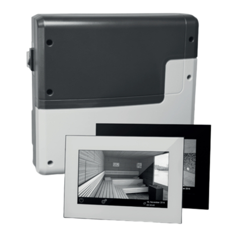
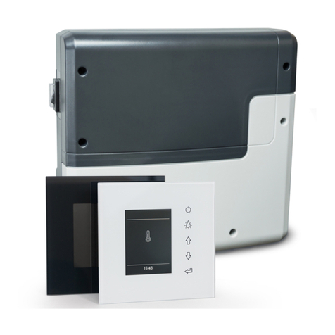
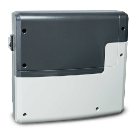
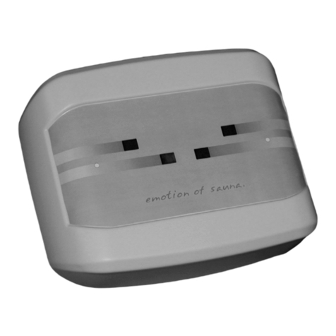
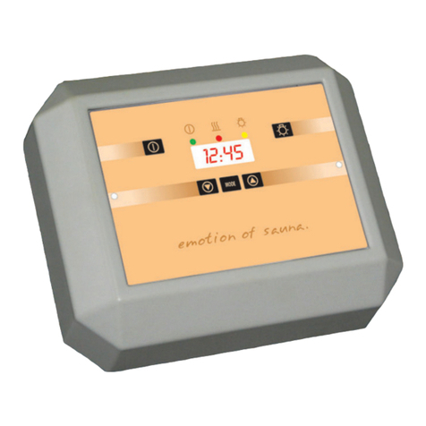
EOS Infratec Classic Planning guide

1
D
Made in Germany
Infratec Classic
Druck Nr. 29343654en / 07.17
GB Assembly and operating instruction
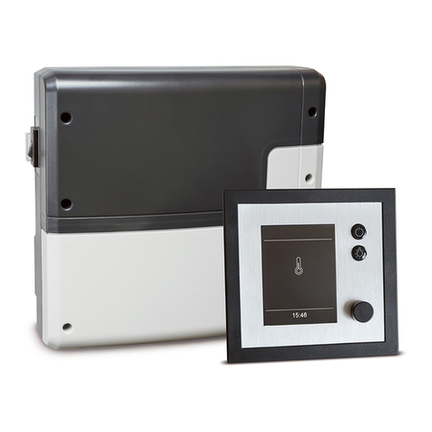
control unit for infrared cabins

2GB
English
Table of Contents
Technical data ...............................................................................................................................................3
General Information ...................................................................................................................................4
General Safety Precautions......................................................................................................................4
Electrical installations.................................................................................................................................6
Connection of IR radiators........................................................................................................................6
Installation of the cabin lighting............................................................................................................7
Connection diagram...................................................................................................................................8
Operation
Setting the display language ..................................................................................................................9
Starting the unit ........................................................................................................................................ 10
Cabin lighting............................................................................................................................................. 10
Switching on the IR radiator ................................................................................................................. 10
Switching off the IR radiator ................................................................................................................. 10
Setting the heating time........................................................................................................................ 11
Setting the cabin temperature ............................................................................................................ 11
Error messages and troubleshooting................................................................................................ 12
Service Address ......................................................................................................................................... 13
Terms and conditions of service.......................................................................................................... 14

3
GB
Technical data
Voltage: 230 V N AC 50 Hz
Fusing: 1 x 16 A
Power intake : max. 3500 W
Control range: 30 - 60° C
Control characteristics: Digital, two-point control
Sensor system: KTY sensor
Heating time limitation: 1 - 99 Minutes
Ambient temperature: -10 bis 40° C
Installation dimensions HxWxD: 139 x 194 x 49 mm
The delivery package includes the following components:
• accessory bag, including: 4 tension-plate screws 4 x 20 mm
• Temperature sensor board with KTY sensor, sensor housing, two 3x25 mm fastening screws and
a 2,0 m sensor cable.

4GB
Dear Customer,
With this IR controller you have purchased a
high quality electronic appliance developed
and produced in conformance with the latest
standards and quality guidelines.
Read these instructions carefully to familiarize
yourself quickly and simply with the unit.
General Information
The IR controller is designed for a voltage of
230 V 50 Hz as a standard feature and requires a
separate 16 A fuse.
Assembly and connection of the infrared
equipment and other electric facilities must
only be carried out by a qualied specialist;
in this regard, VDE 0100 Part 703/2006-2 is
to be complied.
Please read the following installation and
operating instructions thoroughly to ensure
malfunction-free operation of your IR controller.
General Safety Precautions
• Ensure that the electrical installation is
carried out only by an authorized electri-
cian.
• Observe the regulations of our electrical
power supply company as well as all ap-
plicableVDE regulations (DINVDE 0100) or
the applicable national or local norms and
regulations.
• Caution! Lethal Hazard: Never at-
tempt to repair or install the unit yourself.
Ensure that the housing cover is removed
only by a trained employee.
• Use the unit only for the intended purpose
for control of IR emitters.
• When installing or working on the system
ensure that all poles are separated from
the line power, i.e. switch o circuit break-
ers or main switch.
• Observe safety and installation instruc-
tions of the manufacturer.
• Thisdevicehasnotbeendesignedforbeing
used by persons (including children) that
are physically or mentally handicapped
or have sensory disabilities. Moreover, it
is not allowed to use this device without
sucient experience and/or knowledge,
unless these persons will be supervised by
persons responsible for their security or in
case they have been instructed how to use
this device.
• Children are to be supervised in order to
make sure that they do not play with this
device.

5
GB
The control unit (item no 94.4334) is supplied
with pre-mounted electric cables.
The control unit includes the following cables:
• Power line to grounding type plug
• Connector cable for IR radiator(s)
• Connector cable for cabin lighting
• Sensor line (red)
• Temperature limiter line (white)
• The connecting cable for IR radiators is
equipped with a plug adaptor with 5 out-
puts. By using this adaptor you can directly
connect up to 5 IR radiators or add further
radiators by using another plug adaptor.
The control panel (item no. 94.4388) is supplied
without pre-mounted electric cables
The delivery includes:
• Sensor cable (red)
• Temperature limitation sensor cable (white)
Not included are (to be supplied, installed and
connected at site):
• Power supply cable (mains)
• Connection cable for IR radiators
• Connection cable for light
All cables must be heat-resistant to at least
90°C
If you need to connect more than 1 IR radiator,
which is most commonly the case, please make
sure to use one or several plug adaptors (item no.
944960). The plug adaptor has 5 outputs which
allows to connect up to 5 IR radiators directly or
add further radiators by using several adaptors.
NOTICE: make sure that the total number
of connected radiators does not exceed the
• Feed the connecting cables inside cabin wall
through towards the ceiling. See below illus-
tration.
• If the cables cannot be laid inside the cabin
wall they must be placed inside the cabin.
• Make sure to observe installation instruction
for IR radiators. Connecting cables must be
heat-resistant to at least 90°C.
• On the outer side of the cabin ceiling or in-
side cabin ceiling you may then connect the
cable lines to the separate IR radiators.
Attention! The control unit must not
be installed inside the IR cabin.
Installation
181 mm
126 mm
178 mm
114 mm
45 mm 45 mm
maximum allowed load. The maximum load
on the output may not exceed 3.5 kW.
• The cable for cabin lighting shall be connect-
ed to the lighting in the cabin (max. 100 W).
• For control unit installation make a cut-out in
the cabin wall as per drawing given below.
• The wall aperture on the outside of the cabin
shall be ideally made at eye level next to the
door. The opening must be 178 mm wide
and 114 mm high.
• The installation depth is 45 mm.

6GB
Electrical connections
Attention!
The electrical installation may be only car-
ried out by a registered electrical contrac-
tor, while adhering to the EU, national and
local directives for electric installations.
Connection of IR radiators
Mount the IR radiator according to the mount-
ing instructions supplied with IR radiator.
EOS IR radiators include connecting cable with
the Wieland type plug (female).
The output cable line of the control unit includes
the female plug and corresponding plug adap-
tor to connect up to 5 lines to IR radiators. To
connect the line:
• Unscrew the two screws of the clamped cov-
ering for connecting the cable with the plug
adaptor. Insert the plug into the free socket
of the plug adaptor and retighten the two
screws.
• The covering secures the plug connection
and prevents the accidental disconnection
of the joint.
See illustration on the right for details of con-
necting the cable line to the plug adaptor.
screws
clamped covering
plug adaptor
181 mm
126 mm
190 mm
135 mm
• After tting the cables insert the control unit
into the prepared rectangular opening.
• Attach the housing to the cabin wall by using
the 4 included fastening screws
• Next, we suggest that the cable be laid be-
hind a node board. If a IR radiator has also
been installed in this node board, it must be
located below the control unit. IR control
Node board
IR radiator
Attention! Because of the higher start-
ing current by certain IR radiator types the
unit has to be fused by a 16A circuit breaker
with K characteristic (slow reacting fuse).

7
GB
The Infratec Classic control units with-
out pre-installed cables (item no. 94.4388)
shall be connected only with the cable resist-
ant to at least 90°C according to the given
below connection diagram.
• Only IR radiators as per DIN 60335 or
IR heating foils with integrated overheat-
ing protection (140°C) may be connected.
• Follow the safety and installation infor-
mation provided by the IR radiant heater
manufacturer.
Installation of the lighting
• The connection cable is to be fed through
the hole drilled beforehand, and is to be con-
nected to the cabin lighting.
• The cabin lighting must always be mounted
as far as possible from the positional spot of
the infrared emitter, and may not be placed
within the direct heat radiation angle.
1. The temperature sensor shall be mounted in
the centre of the cabin ceiling.
2. Drill a hole to lead the cable through the ceil-
Housing
Sensor circuit
board
Sensor
S1 S2
Ceiling panel hole
Cabin ceiling
Centre sensor housing on
middle section Sensor cable
Terminals in control unit
ing, preferably through the middle of one of
the wooden boards.
3. Guide the sensor cable through the drilled
hole.
4. Connect the sensor cable to the sensor board
terminals as shown below.
5. Attach the sensor board to the ceiling with
two included screws and t the sensor hous-
ing (cap) to the board. Make sure it sits tightly.
6. Connect the sensor cable to the control unit
terminals as shown on the connection dia-
gram. See illustration below for details.
Installation of the tempera-
ture sensor

8GB
Connection diagram
S e n s o r
Verteilerblock
C o n ne c ti on b ox
I R -E m itte r
I R -E m itte r
I R -E m itte r
I R -E m itte r
I R -E m itte r
Infratec Classic
2 3 0 V AC
NNN
N
LLL
LPE
PEPE
Licht LSG IR-
Strahler Netz
bauseitige Lasterweiterung
Power rating extension
by customer
Attention!
Dear customer,
according to the valid regulations, the electrical connection of the heating equipment
and the control box has to be carried out through the appropriately qualied specialist
(electrician).
Please bear in mind that in case of a warranty claim, you are kindly requested to present a
proof that the installation has been carried out by an authorized person (e.g. invoice copy
from the electric shop or dealer).

9
GB
Controls
On / o
Light on / o
Infratec
Display
Standby switch
Control buttons - up/down
Mode button - temperature
Mode button - heating time
Setting the display language
The unit comes preset with German as the display language. To change the display language to
English, rst switch o the unit using the Standby switch. Then hold down the heating time and
temperature mode buttons while switching the unit back on with the Standby switch. The display
will now be in English.
To switch back to German display mode, follow the corresponding steps.

10 GB
Starting the unit
Activate the Standby switch.
The unit displays a brief greeting and
enters Standby mode. The display displays the
current temperature in the cabin.
Hello
ready T: 28°C
Cabin lighting
To switch the cabin lighting on or o, press the
light button.
To switch on the IR radiator, press the -button.
The display indicates the current cabin temper-
ature (T) and the remaining heating time (t) in
MM: SS.
T: 35°C t :45:11
Switching o the IR radiator
When the heating period ends, the unit auto-
matically switches o the IR radiator and enters
Standby mode.
To finish the IR bath sooner, activate the
button.The IR radiators are switched o and the
unit enters Standby mode.
Switching on the IR radiator

11
GB
set temp: 30°C
Setting the cabin temperature
Using the control unit you can preset the cabin
temperature between 30° to 70°C.
First, select the -button to switch to control
mode.
Now set the desired temperature using the
and buttons.
Finally, press the -button again.
Please notice that the control unit will switch the
IR radiators on and o as per air temperature as
measured by the temperature sensor.
The temperature regulation is therefore based
on the pre-set temperature and sensor position
in the cabin.
Depending on the individual cabin situation
the effective temperature inside the IR cabin
may vary. This may inuence the switching of
the IR radiators.
set temp: 45°C
set time: 25 m
Setting the heating time
You can preset the heating time between 1-99
minutes with the control unit.
First, switch the unit to Standby mode.
Next, select the -button to switch to control
mode.
Now set the desired heating time using the
and buttons.
Finally, press the -button again. The new
setting is saved and the unit returns to Standby
mode.
set time: 60 m

12 GB
sensor error
Error indicators
If the sensor is defective, the message shown
opposite appears in the display. Have the unit
examined by a trained technician.
Reference value = approx. 2 k Wat 20° C
sensor short error
Temperature sensor fault / circuit broken
Temperature sensor short circuit

Service Address:
EOS Saunatechnik GmbH
Schneiderstriesch 1
35759 Driedorf, Germany
Tel: +49 (0)2775 82-514
Fax: +49 (0)2775 82-431
www.eos-sauna.de
Please keep this address in a safe place togeth-
er with the installation guide.
To help us answer your questions quickly and
competently please provide the information
printed on the type shield including the model,
item no. and serial no., in all inquiries.
Equipment commissioning date:
Stamp and signature of the authorized elec-
trician:
13
GB

General Terms and Conditions of Service
I. Scope
Unless otherwise agreed in writing in a specic case,
these terms and conditions of service shall apply to ser-
vice operations, including examining and repairing com-
plaints. All our existing or future legal relationships shall
be governed solely by the following terms and condi-
tions of service. Our recognition of any conicting terms
and conditions of the Ordering Party shall be conditional
upon our having given our express written consent to
their applicability. We hereby expressly object to any
terms and conditions of the Ordering Party contained
in its General Terms and Conditions of Business or order
conrmation. If order conrmations or deliveries are ac-
cepted without reservation, this shall not be deemed to
constitute recognition of such terms and conditions. Any
ancillary agreements or amendments must be conrmed
in writing.
II. Prices and Payment Terms
The Ordering Party shall bear the following costs in
connection with the service operation:
• Disassembly/assembly and electrical (de-) instal-
lation
• Transportation, postage and packaging
• Function testing and troubleshooting including
inspection and repair costs
There shall be no third-party billing.
III. Performance Obligations / Ordering Party‘s
Cooperation
The Ordering Party shall provide free-of-charge assis-
tance to the manufacturer in carrying out the service
operation.
In the case of a warranty claim, the manufacturer
shall make the replacement parts necessary for the
service available to the Ordering Party free of charge.
IV. Service Visit by the manufacturer
In the event that it is essential that a manufacturer
employee carry out the service operation on site, this
must be agreed in advance. Where the main reason
for the service call is not the fault of the manufactur-
er, any costs incurred shall be recharged to the Order-
ing Party after the service visit.
V. Liability
The manufacturer shall assume liability in accordance
with the currently applicable statutory regulations. The
packaging for all of our products is designed for the ship-
ping of individually packed goods (pallet). We expressly
point out that our packaging is not suitable for individual
shipments via parcel post. The manufacturer shall accept
no liability for damage incurred as a result of improper
packaging in an individual shipment.
VI. Manufacturer‘s Warranty
The manufacturer‘s warranty shall apply only in the
event that installation, operation and maintenance have
been carried out in accordance with the manufacturer‘s
specications contained in the assembly instructions
and instructions for use.
•Thewarrantyperiodshallcommencefromthedate
on which proof of purchase is provided and shall be
limited, in principle, to 24 months.
• Warranty services shall be performed only if the
proof of purchase relating to the equipment can be
presented.
• Any and all warranty claims shall become void if
modications are made to the equipment without
the manufacturer‘s express consent.
• Any warranty claim shall likewise become void in
the case of defects that arise due to repairs or inter-
ventions made by unauthorized persons or due to
improper use.
•Inthecaseofwarrantyclaims,theserialandarticle
numbers must be indicated together with the desig-
nation and a meaningful description of the fault.
•Thiswarrantyshallcoverdefectiveequipmentparts,
with the exception of normal wear parts. Wear parts
shall include, among other things, light sources, start-
ers, gas or oil pressure dampers as well as acrylic glass
panes, tubular heating elements and sauna heater
stones.
•Onlyoriginalreplacementpartsmaybeusedwithin
the warranty.
•Servicevisitsbyoutside companiesshallrequirea
written order to be issued by our service department.
• The equipment in question shall be sent to our
service department by the Ordering Party and at its
expense.
•Electricalassemblyandinstallationwork,including
in the event of service or replacement, shall be car-
ried out at the Customer‘s expense and shall not be
borne by the manufacturer.
Complaints in respect of our products shall be reported
to the specialist trader responsible and shall be exclu-
sively handled via the latter.
The manufacturers General Terms and Conditions of
Business, as amended, shall apply in addition to the fore-
going terms and conditions of service.
As of 06/2015
14 GB
Other manuals for Infratec Classic
2
Table of contents
Other EOS Control Unit manuals

EOS
EOS SBM App Module Manual instruction

EOS
EOS InfraStyle User manual

EOS
EOS ECON H2 Planning guide

EOS
EOS WCI-01 User manual

EOS
EOS EmoTouch 3 User manual

EOS
EOS ECON 45A2 Planning guide

EOS
EOS EMOTEC DC 9000 User manual

EOS
EOS ECON S2 User manual

EOS
EOS EmoTec LSG 09R Planning guide

EOS
EOS EmoTouch II + User manual
Popular Control Unit manuals by other brands

Toshiba
Toshiba G3 Plus Pack specification

Aventics
Aventics PILOTAIR A Series Service information

gefran
gefran R-TC8 Installation and operation manual

Nanotron Technologies
Nanotron Technologies nanoLOC AVR Module user manual

Sauer Sundstrand
Sauer Sundstrand MCV104A5927 quick start guide

SWARCO
SWARCO CAIMAN SRO INSTALLER QUICK-REFERENCE GUIDE