EN
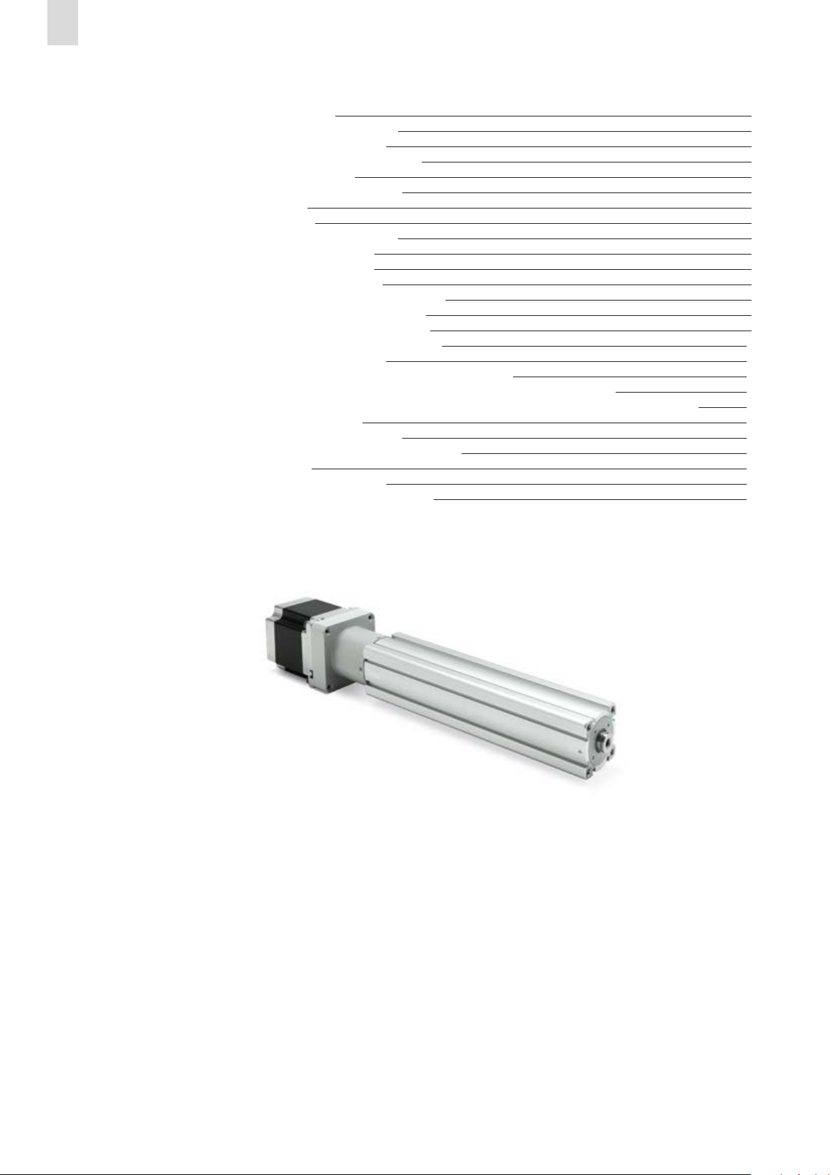
Series 3E electromechanical cylinders
3
General safety warnings
Introduction
Reference documents
1.
i.
2.
This user manual must be read completely before starting assembly
and commissioning of the Series 3E electromechanical cylinder. This
document provides information on some specific product features but
does not intervene on the correct application of the product under
certain conditions.
- All provisions, laws and regulations valid in the place of destination of
the product must always be observed.
- Series 3E electromechanical cylinder must be used free from
tampering or damage and in the original condition of delivery.
- The general catalogue Series 3E (available on our website) defines the
limits of use within which this cylinder must be applied.
- The products indicated in this document are subject to performance
deterioration due to wear of the components subjected to the loads
and expected working conditions or to aging of the components.
- This document provides warnings relating to the Series 3E
electromechanical cylinder.
Assessment of any interactions with other components, objects or
persons inside a machine or application has to be carried out by the
designer and installer of the machine or application.
- Some hazards can only be associated with the product after it has been
installed on the machine/equipment. It is the responsibility of the
end user t identify these hazards and reduce the risks associated with
Before installing the Series 3E electromechanical cylinder, the installation
engineer must ensure the following documentation is at disposal:
[1] - In case of installation on board a machine or inside an application, make sure you have all documentation at hand relating to that application, in
order to be able to assess any risks to objects, persons or animals.
Title of document Application
Instruction sheet (supplied in the packing) Basic information
Series 3E electromechanical cylinders Electric actuation catalogue
Drives Series DRCS and DRVB to
control electric actuation Electric actuation catalogue
Motors Series MTS and MTB
for electric actuation Electric actuation catalogue
Instruction sheet Drives DRWB
for brushless motors Basic information
Instruction sheet Drives DRCS
for Stepper motors Basic information
Documentation relating to the application
in the system and instructions of other components [1] -
The final user must perform controls and assessments necessary to
validate the use of the product.
© All rights of reproduction, distribution and use of this document are
property of Camozzi Automation S.p.A.
The original instructions were written in Italian.
them.
- Series 3E electromechanical cylinders are designed for industrial use, they
are not suitable for potentially explosive environments and for underwater
use.
- When using Series 3E electromechanical cylinder in potentially corrosive
environments, consult Camozzi Automation S.p.A.
- Avoid covering Series 3E electromechanical cylinder with paint or other
substances; do not use in direct contact with corrosive gases, chemicals,
acids, salt water or steam.
- Protection class IP40 is guaranteed only and exclusively when using
dedicated accessories.