Campbell 10164-L User manual

10164-L Sampler Control
Cable for use with Isco and
Sigma Autosamplers
Revision: 9/12
Copyright © 1998-2012
Campbell Scientific, Inc.


Warranty
“PRODUCTS MANUFACTURED BY CAMPBELL SCIENTIFIC, INC. are
warranted by Campbell Scientific, Inc. (“Campbell”) to be free from defects in
materials and workmanship under normal use and service for twelve (12)
months from date of shipment unless otherwise specified in the corresponding
Campbell pricelist or product manual. Products not manufactured, but that are
re-sold by Campbell, are warranted only to the limits extended by the original
manufacturer. Batteries, fine-wire thermocouples, desiccant, and other
consumables have no warranty. Campbell's obligation under this warranty is
limited to repairing or replacing (at Campbell's option) defective products,
which shall be the sole and exclusive remedy under this warranty. The
customer shall assume all costs of removing, reinstalling, and shipping
defective products to Campbell. Campbell will return such products by surface
carrier prepaid within the continental United States of America. To all other
locations, Campbell will return such products best way CIP (Port of Entry)
INCOTERM® 2010, prepaid. This warranty shall not apply to any products
which have been subjected to modification, misuse, neglect, improper service,
accidents of nature, or shipping damage. This warranty is in lieu of all other
warranties, expressed or implied. The warranty for installation services
performed by Campbell such as programming to customer specifications,
electrical connections to products manufactured by Campbell, and product
specific training, is part of Campbell’s product warranty. CAMPBELL
EXPRESSLY DISCLAIMS AND EXCLUDES ANY IMPLIED
WARRANTIES OF MERCHANTABILITY OR FITNESS FOR A
PARTICULAR PURPOSE. Campbell is not liable for any special, indirect,
incidental, and/or consequential damages.”

Assistance
Products may not be returned without prior authorization. The following
contact information is for US and international customers residing in countries
served by Campbell Scientific, Inc. directly. Affiliate companies handle
repairs for customers within their territories. Please visit
www.campbellsci.com to determine which Campbell Scientific company serves
your country.
To obtain a Returned Materials Authorization (RMA), contact CAMPBELL
SCIENTIFIC, INC., phone (435) 227-9000. After an applications engineer
determines the nature of the problem, an RMA number will be issued. Please
write this number clearly on the outside of the shipping container. Campbell
Scientific's shipping address is:
CAMPBELL SCIENTIFIC, INC.
RMA#_____
815 West 1800 North
Logan, Utah 84321-1784
For all returns, the customer must fill out a "Statement of Product Cleanliness
and Decontamination" form and comply with the requirements specified in it.
The form is available from our web site at www.campbellsci.com/repair. A
completed form must be either emailed to repair@campbellsci.com or faxed to
(435) 227-9106. Campbell Scientific is unable to process any returns until we
receive this form. If the form is not received within three days of product
receipt or is incomplete, the product will be returned to the customer at the
customer's expense. Campbell Scientific reserves the right to refuse service on
products that were exposed to contaminants that may cause health or safety
concerns for our employees.

Table of Contents
PDF viewers: These page numbers refer to the printed version of this document. Use the
PDF reader bookmarks tab for links to specific sections.
1. General ........................................................................1
2. Specifications .............................................................1
2.1 Cable Length Considerations ...............................................................1
3. Wiring...........................................................................2
3.1 General Wiring Information.................................................................2
3.2 Triggering Sampler ..............................................................................3
3.3 Sense Sampler Event Markers..............................................................3
3.4 Inhibit Sampler’s Program ...................................................................3
4. Programming ..............................................................4
4.1 CRBasic Programming.........................................................................5
4.1.1 Trigger Sampler ............................................................................5
4.1.2 Sense Sampler Event.....................................................................5
4.1.3 Inhibit Sampler’s Program ............................................................6
4.2 Edlog Programming .............................................................................7
4.2.1 Trigger Sampler ............................................................................7
4.2.2 Sense Sampler Event Markers ......................................................8
4.2.2.1 Pulse Port Method ..............................................................8
4.2.2.2 CR10(X) Control Port Interrupt Method............................8
4.2.3 Inhibit Sampler’s Program ............................................................9
Figure
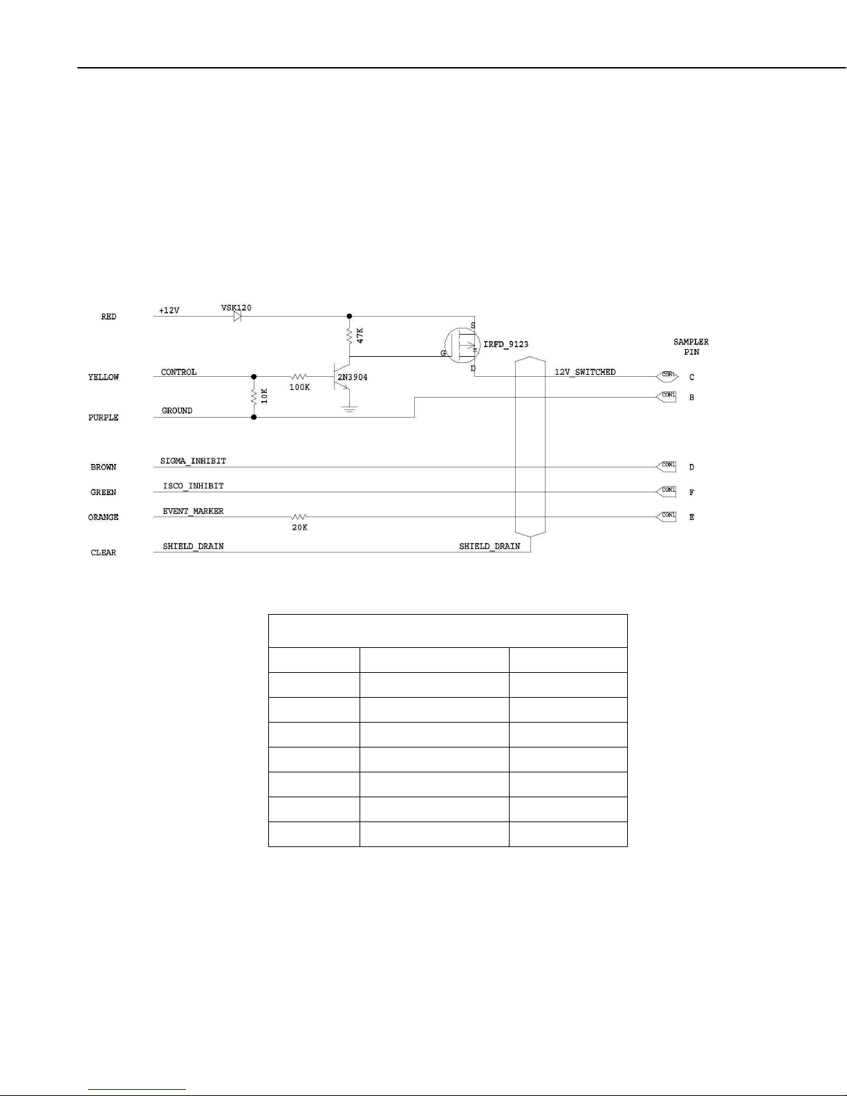
3-1. 10164 Sampler Control Cable Schematic ............................................2
Tables
3-1. Technical Details of Cable Design.......................................................2
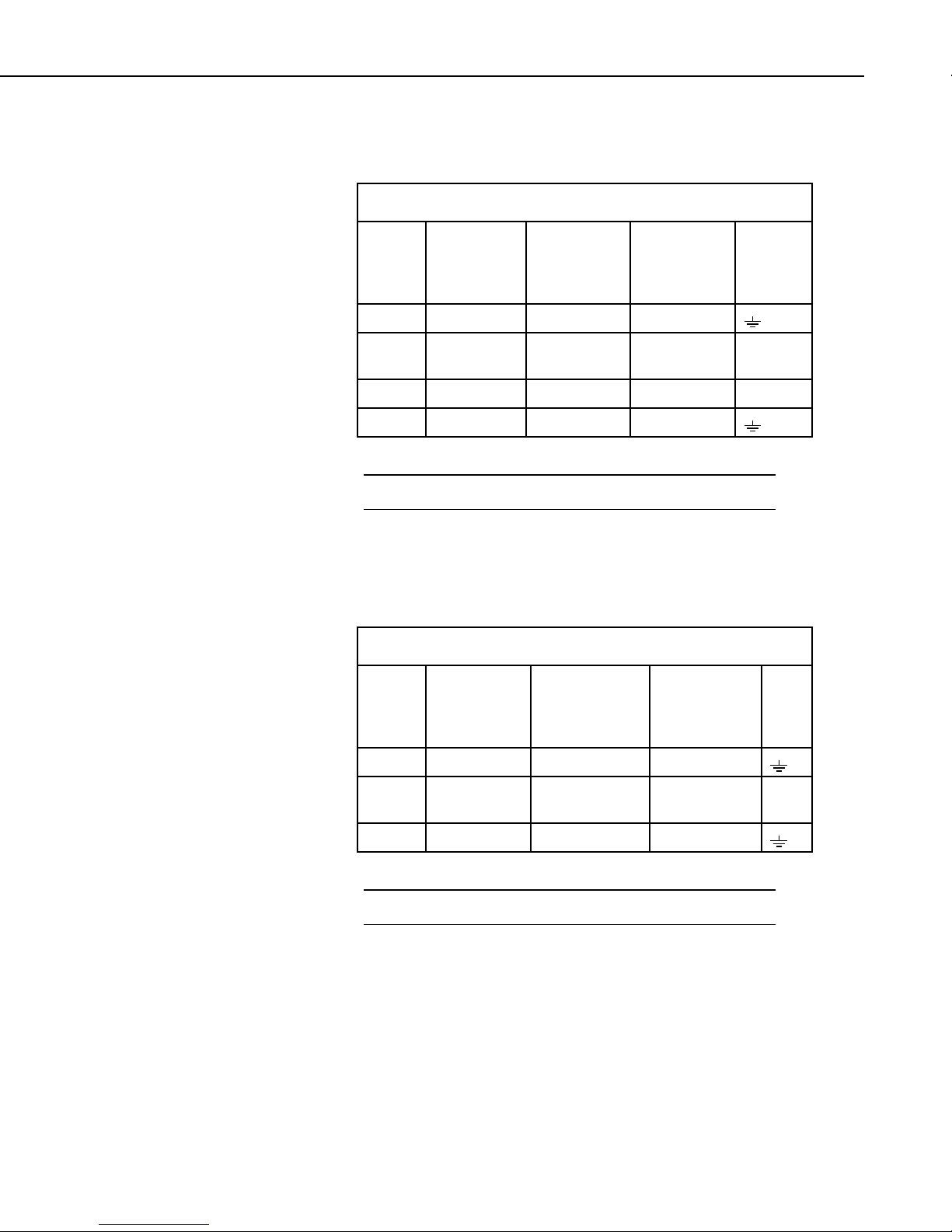
3-2. Datalogger Wiring for Triggering Sampler..........................................3
3-3. Datalogger Wiring for Sampler Event Marker.....................................3
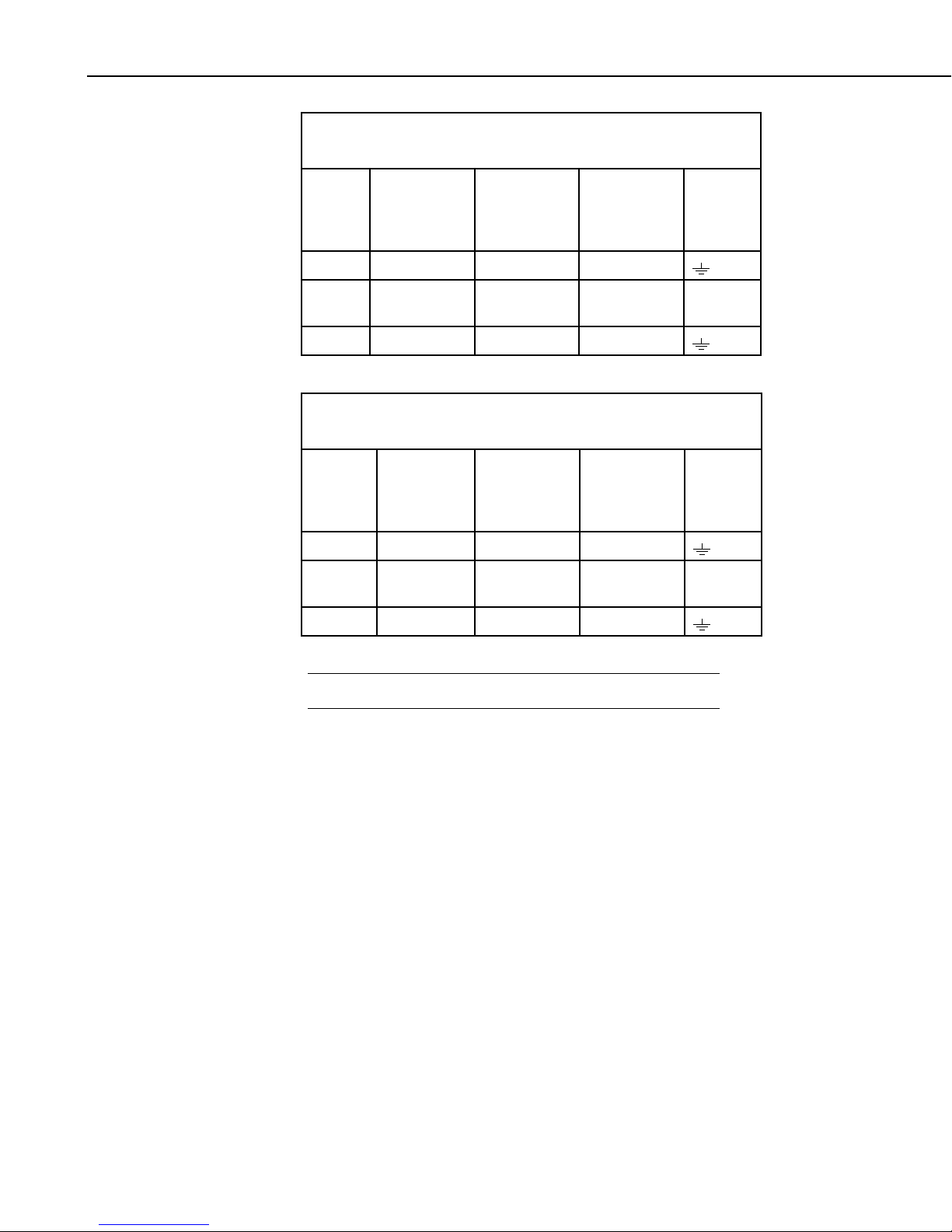
3-4. Datalogger Wiring to Inhibit a Sigma Sampler Program ....................4
3-5. Datalogger Wiring to Inhibit an Isco Sampler Program......................4
4-1. Wiring for CRBasic Triggering Sampler Example ..............................5
4-2. Wiring for CRBasic Sampler Event Marker Example .........................5
4-3. Wiring for Example of Inhibiting an Isco Onboard Program..............6
4-4. Wiring for Example of Inhibiting a Sigma Sampler Onboard
Program ............................................................................................7
i

Table of Contents
ii

10164-L Sampler Control Cable for use
with Isco and Sigma Autosamplers
1. General
The 10164-L sampler control cable enables a datalogger to trigger an Isco,
American Sigma, or connector-compatible autosampler. Through this cable,
the datalogger can inhibit the sampler from running its programmed sampling
routine and sense and record when the sampler indicates that it has taken a
sample. Each of these functions is independent of the others and may be
combined as desired.
2. Specifications
Sampler Connection: mil-spec, 6-pin circular connector (shell size 14)
Datalogger Connection: pigtail with individual conductors
Current Drain: < 1 mA; consult the specifications of the connected
sampler to determine its power considerations.
Cable Length: 50 ft standard; 1000 ft maximum (see Cable Length
Considerations)
2.1 Cable Length Considerations
In most applications, the 10164 cable connects the datalogger to a sampler
residing in the same instrumentation shack. Therefore, a cable length of 50 ft
or less is typically used.
Cable lengths up to 1000 ft are possible if the sampler supports long event
markers. For example, the Isco-brand sampler has a 3 second event marker,
which is an adequate duration for a 1000 ft cable length.
The 10164 does not include surge protection. Therefore,
longer cables need to be protected from surges in order to
safeguard the system from electrical transients. A
recommended method of doing this is to place the cable in
a metal conduit and then bury the conduit at a depth of at
least one foot.
CAUTION
1

10164-L Sampler Control Cable for use with Isco and Sigma Autosamplers
3. Wiring
3.1 General Wiring Information
FIGURE 3-1 shows a schematic of the 10164 and TABLE 3-1 shows pin
connector and wire functions.
Sections 3.2 through 3.4 provide information about connecting the wires to a
datalogger. The datalogger wiring depends on the function.
FIGURE 3-1. 10164 Sampler Control Cable Schematic
TABLE 3-1. Technical Details of Cable Design
Wire Color Via Connector Pin
brown direct D
green direct F
purple direct B
yellow solid state relay circuit none (controls C)
red solid state relay circuit C
orange 20 kohm resistor E
clear cable shield no connection
2

10164-L Sampler Control Cable for use with Isco and Sigma Autosamplers
3.2 Triggering Sampler
TABLE 3-2 shows the datalogger connections required to trigger the sampler.
TABLE 3-2. Datalogger Wiring for Triggering Sampler
Color
Description
CR800
CR850
CR1000
CR3000
CR500
CR510
CR10(X)
CR23X
21X
Purple Ground G G
Yellow Control Port Control Port
(C1, C2,…)
Control Port
(C1, C2,…)
Control
Red Power 12V 12V +12
Clear Shield G G
Insulate and tuck the unused wires out of the way.
NOTE
3.3 Sense Sampler Event Markers
TABLE 3-3 shows the datalogger connections required to sense the sampler
events.
TABLE 3-3. Datalogger Wiring for Sampler Event Marker
Color
Description
CR800
CR850
CR1000
CR3000
CR500
CR510
CR10(X)
CR23X
21X
Purple Ground G G
Orange Pulse Pulse Channel
(P1, P2,…)
Pulse Channel
(P1, P2,…)
Pulse
Clear Shield G G
Insulate and tuck the unused wires out of the way.
NOTE
3.4 Inhibit Sampler’s Program
Some samplers run their own program that you might want to inhibit. The
wiring for inhibiting the sampler’s onboard program depends on the program’s
logic. TABLE 3-4 shows the wiring for Sigma samplers that require a control
port to be set high to inhibit their onboard program. TABLE 3-5 shows the
wiring for Isco samplers that require a control port to be set low to inhibit their
onboard program.
3

10164-L Sampler Control Cable for use with Isco and Sigma Autosamplers
TABLE 3-4. Datalogger Wiring to Inhibit a
Sigma Sampler Program
Color
Description
CR800
CR850
CR1000
CR3000
CR500
CR510
CR10(X)
CR23X
21X
Purple Ground G G
Brown Control Port Control Port
(C1, C2,…)
Control Port
(C1, C2,…)
Control
Clear Shield G G
TABLE 3-5. Datalogger Wiring to Inhibit an
Isco Sampler Program
Color
Description
CR800
CR850
CR1000
CR3000
CR500
CR510
CR10(X)
CR23X
21X
Purple Ground G G
Green Control Port Control Port
(C1, C2,…)
Control Port
(C1, C2,…)
Control
Clear Shield G G
Insulate and tuck the unused wires out of the way.
NOTE
4. Programming
The datalogger is programmed using either CRBasic or Edlog. Dataloggers
that use CRBasic include the CR800, CR850, CR1000, and CR3000.
Dataloggers that use Edlog include the CR10(X), CR510, CR500, CR23X, and
21X.
With this cable, the datalogger can be programmed to:
•Trigger the sampler
•Sense and record when the sampler has taken a sample
•Inhibit the sampler from running its onboard sampling routine
Each of these functions is independent of the others and may be combined as
desired.
4

10164-L Sampler Control Cable for use with Isco and Sigma Autosamplers
4.1 CRBasic Programming
4.1.1 Trigger Sampler
To trigger the sampler, the datalogger program must set the port high, delay for
at least 0.5 seconds, and then set the port low.
TABLE 4-1. Wiring for CRBasic
Triggering Sampler Example
Color Description CR800, CR850, CR1000, or CR3000
Purple Ground G
Yellow Control Port C2
Red Power 12V
Clear Shield G
For example, if control port 2 is used (see TABLE 4-1), a datalogger program
that includes the following CRBasic instructions will trigger the sampler:
PortSet(2,1)
Delay(0,50,mSec)
PortSet(2,0)
Above is only a portion of the CRBasic program.
NOTE
4.1.2 Sense Sampler Event
To sense the sampler event, use the PulseCount() instruction with the PConfig
parameter set to high frequency (code 0). The value stored in the variable
should be totalized.
The following example program will sense the sampler events when the cable
is wired to pulse channel 1 (see TABLE 4-2).
TABLE 4-2. Wiring for CRBasic
Sampler Event Marker Example
Color Description CR1000
Purple Ground G
Orange Pulse P1
Clear Shield G
5

10164-L Sampler Control Cable for use with Isco and Sigma Autosamplers
'CR1000 Series Datalogger
'Declare Public Variables
Public Events
'Define Data Tables
DataTable (Sampler,1,1000)
Totalize (1,Events,FP2,False)
EndTable
'Main Program
BeginProg
Scan (1,Sec,0,0)
PulseCount (Events,1,1,0,0,1.0,0)
'Call Output Tables
CallTable Sampler
NextScan
EndProg
4.1.3 Inhibit Sampler’s Program
To inhibit a sampler’s onboard program, use the PortSet() instruction.
Whether the port should be set low or high depends on the onboard program’s
logic. For samplers such as the products manufactured by Isco, the onboard
program is inhibited by setting the control port low.
TABLE 4-3. Wiring for Example of Inhibiting an
Isco Onboard Program
Color Description CR800, CR850, CR1000, or CR3000
Purple Ground G
Green Control Port C1
Clear Shield G
For example, if the cable is wired as shown in TABLE 4-3, a datalogger
program that includes the following CRBasic instruction will inhibit an Isco
sampler’s onboard program:
PortSet(1,0)
Above is only a portion of the CRBasic program.
NOTE
After an Isco sampler’s program has been inhibited, it can be allowed to run by
setting the port high.
6

10164-L Sampler Control Cable for use with Isco and Sigma Autosamplers
TABLE 4-4. Wiring for Example of Inhibiting a
Sigma Sampler Onboard Program
Color Description CR800, CR850, CR1000, orCR3000
purple Ground G
brown Control Port C1
clear Shield G
For samplers such as the products manufactured by Sigma, the onboard
program is inhibited by setting the control port high.
For example, if the cable is wired as shown in TABLE 4-4, a datalogger
program that includes the following CRBasic instruction will inhibit a Sigma
sampler’s onboard program:
PortSet(1,1)
Above is only a portion of the CRBasic program.
NOTE
After a Sigma sampler’s program has been inhibited, it can be allowed to run
by setting the port low.
4.2 Edlog Programming
4.2.1 Trigger Sampler
Wire Color CR10(X)
Purple G
Yellow C2
Red 12V
Clear G
To trigger the sampler, pulse port 2 using a set of instructions such as follows:
Do (P86)
1: 42 Set Port 2 High
; Note: The 50 in the third parameter keeps the
; port high for 0.5 seconds. Some users have
; reported using a delay of 1 sec (100 in
; parameter 3) to ensure reliable triggering of
; the sampler.
Excitation with Delay (P22)
1: 1 Ex Channel
2: 0 Delay W/Ex (units = 0.01 sec)
3: 50 Delay After Ex (units = 0.01 sec)
4: 0 mV Excitation
7

10164-L Sampler Control Cable for use with Isco and Sigma Autosamplers
Do (P86)
1: 52 Set Port 2 Low
You can also supply the trigger signal from switched excitation if no control
ports are available. In this case, connect the yellow cable to the desired
excitation channel (say E3) and pulse the channel using Instruction 22 as
follows:
Excitation with Delay (P22)
1: 3 EX Chan (or the channel you select)
2: 50 Delay w/EX (units=0.01sec)
3: 0 Delay after EX (units=0.01sec)
4: 2500 mV Excitation
4.2.2 Sense Sampler Event Markers
4.2.2.1 Pulse Port Method
Wire Color CR10(X)
Purple G
Orange P1
Clear G
To sense sampler events, use Instruction 3 with a configuration code of 0.
Pulse (P3)
1: 1 Reps
2: 1 Pulse Input Chan
3: 0 High frequency (configuration code)
4: 2 Loc [:EVENTS]
5: 1 Mult
6: 0 Offset
To record the events in the datalogger's final storage area, remember to totalize
the events temporarily stored in Input Location 2 in this example.
4.2.2.2 CR10(X) Control Port Interrupt Method
For the CR10(X), there is another useful method for sensing and recording
sampler events. This method uses the control port 8/subroutine 98 interrupt
feature of the CR10(X). Each time the sampler reports an event, the CR10(X)
records the sample number with a time stamp in final storage. In this example,
sampler events will show up as output arrays with an array ID of 400.
Wire Color CR10(X)
Purple G
Orange C8
Clear G
8

10164-L Sampler Control Cable for use with Isco and Sigma Autosamplers
CR10(X) Program (Subroutine 98 in Program Table 3)
* 3 Table 3 Subroutines
1: Beginning of Subroutine (P85)
1: 98 Subroutine Number
2: Z=Z+1 (P32)
1: 10 Z Loc [ Sample_No ]
3: Do (P86)
1: 10 Set high Flag 0 (output flag)
4: Set Active Storage Area (P80)
1: 1 Final Storage Area 1
2: 400 Array ID or location
5: Real Time (P77)
1: 1110 Year,Day,Hour-Minute
6: Sample (P70)
1: 1 Reps
2: 10 Loc [ Sample_No ]
7: End (P95) ;of Subroutine Number 98
End Table 3
4.2.3 Inhibit Sampler’s Program
Wire Color CR10(X)
Purple G
(Isco) Green C1
(Sigma) Brown C1
Clear G
To inhibit an Isco sampler from running its own program, set control port 1
low using a program control instruction such as Instruction 86. To allow the
sampler to run its program, set it high.
The logic for Sigma samplers is just the opposite. A high signal
inhibits the sampler.
NOTE
Example for inhibiting an Isco sampler's program:
Do (P86)
1: 51 Set Port 1 low ; (41 would set it high)
9

10164-L Sampler Control Cable for use with Isco and Sigma Autosamplers
10


Campbell Scientific Companies
Campbell Scientific, Inc. (CSI)
815 West 1800 North
Logan, Utah 84321
UNITED STATES
www.campbellsci.com • [email protected]
Campbell Scientific Africa Pty. Ltd. (CSAf)
PO Box 2450
Somerset West 7129
SOUTH AFRICA
www.csafrica.co.za • [email protected]
Campbell Scientific Australia Pty. Ltd. (CSA)
PO Box 8108
Garbutt Post Shop QLD 4814
AUSTRALIA
www.campbellsci.com.au • info@campbellsci.com.au
Campbell Scientific do Brazil Ltda. (CSB)
Rua Luisa Crapsi Orsi, 15 Butantã
CEP: 005543-000 São Paulo SP BRAZIL
www.campbellsci.com.br • suporte@campbellsci.com.br
Campbell Scientific Canada Corp. (CSC)
11564 - 149th Street NW
Edmonton, Alberta T5M 1W7
CANADA
www.campbellsci.ca • dataloggers@campbellsci.ca
Campbell Scientific Centro Caribe S.A. (CSCC)
300 N Cementerio, Edificio Breller
Santo Domingo, Heredia 40305
COSTA RICA
www.campbellsci.cc • [email protected]
Campbell Scientific Ltd. (CSL)
Campbell Park
80 Hathern Road
Shepshed, Loughborough LE12 9GX
UNITED KINGDOM
www.campbellsci.co.uk • [email protected]
Campbell Scientific Ltd. (France)
3 Avenue de la Division Leclerc
92160 ANTONY
FRANCE
www.campbellsci.fr • [email protected]
Campbell Scientific Spain, S. L.
Avda. Pompeu Fabra 7-9, local 1
08024 Barcelona
SPAIN
www.campbellsci.es • [email protected]
Please visit www.campbellsci.com to obtain contact information for your local US or international representative.
Table of contents
Other Campbell Cables And Connectors manuals