Can-Am Roadster RT-622 2010 User manual

2010
Service Manual
Roadster
RT-622 Trailer

Legal deposit:
National Library of Quebec
National Library of Canada 2010
All rights reserved. No parts of this manual may be reproduced in any form without the prior written
permission of Bombardier Recreational Products Inc. (BRP)
©Bombardier Recreational Products Inc. (BRP) 2010
Printed in Canada
Technical Publications
Bombardier Recreational Products Inc. (BRP)
Valcourt (Quebec) Canada

TABLE OF CONTENTS
SAFETY NOTICE ........................................................................................................ III
INTRODUCTION......................................................................................................... IV
GENERAL INFORMATION........................................................................................... IV
TRAILER INFORMATION............................................................................................. IV
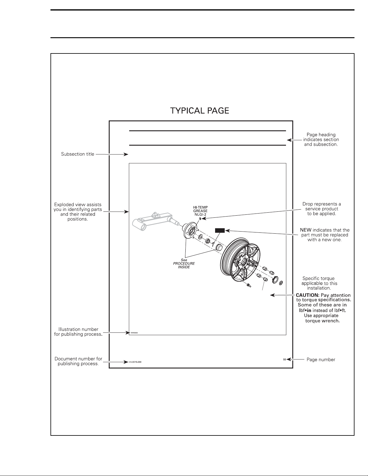
MANUAL INFORMATION............................................................................................ IV
01 MAINTENANCE
01 – MAINTENANCE SCHEDULE.................................................................................... 1
02 – STORAGE AND PRESEASON PREPARATION............................................................... 3
02 CHASSIS
01 – WHEELS AND WHEELS HUBS ................................................................................ 5
GENERAL ...................................................................................................... 6
PROCEDURES................................................................................................. 6
WHEELS .................................................................................................... 6
WHEEL BEARINGS ......................................................................................... 6
WHEEL HUBS .............................................................................................. 7
TIRES ....................................................................................................... 7
02 – SUSPENSION..................................................................................................... 9
GENERAL .................................................................................................... 10
ADJUSTMENT.............................................................................................. 10
SPRING PRELOAD ADJUSTMENT ....................................................................... 10
PROCEDURES............................................................................................... 10
SHOCK ABSORBERS ..................................................................................... 10
SPRING ................................................................................................... 11
TRAILING ARM ........................................................................................... 11
03 – BODY............................................................................................................. 13
GENERAL .................................................................................................... 17
TRAILER CARE ........................................................................................... 17
PROCEDURES............................................................................................... 17
DECALS................................................................................................... 17
ROCK GUARD ............................................................................................ 17
LATCHES.................................................................................................. 17
LATCH CABLES........................................................................................... 17
LOCK PINS................................................................................................ 20
INNER FASCIAS .......................................................................................... 20
FRONT ACCESS COVER.................................................................................. 21
REAR ACCESS COVER ................................................................................... 22
KEY BARREL.............................................................................................. 22
BODY ..................................................................................................... 27
04 – FRAME ........................................................................................................... 31
GENERAL .................................................................................................... 32
PROCEDURES............................................................................................... 32
TONGUE .................................................................................................. 32
COUPLER ................................................................................................. 34
FRAME.................................................................................................... 34
03 ELECTRICAL SYSTEM
01 – LIGHTS AND HARNESS ...................................................................................... 35
GENERAL .................................................................................................... 38
PROCEDURES............................................................................................... 38
TAILLIGHT ................................................................................................ 38
POSITION LIGHT ......................................................................................... 38
TURN SIGNAL LIGHTS AND BACKUP LIGHTS........................................................... 38
I

TABLE OF CONTENTS
03 ELECTRICAL SYSTEM (cont’d)
01 – LIGHTS AND HARNESS (cont’d)
PROCEDURES (cont’d)
LICENSE PLATE LIGHT ................................................................................... 39
HARNESS ................................................................................................. 39
04 TECHNICAL SPECIFICATIONS
01 – RT-622 TRAILER SPECIFICATIONS.......................................................................... 41
II

SAFETY NOTICE
SAFETY NOTICE
This manual has been prepared as a guide to cor-
rectly service the Roadster RT-622 trailer as de-
scribed in the model list in the
INTRODUCTION
.
This edition was primarily published to be used by
mechanical technicians who are already familiar
with all service procedures relating to BRP prod-
ucts. Mechanical technicians should attend train-
ing courses given by BRPTI.
Please note that the instructions will apply only
if proper hand tools and special service tools are
used.
In addition, the sole purpose of the illustrations
throughout the manual, is to assist identification
of the general configuration of the parts. They are
not to be interpreted as technical drawings or ex-
act replicas of the parts.
It is understood that this manual may be trans-
lated into another language. In the event of any
discrepancy, the English version shall prevail.
The contents of this manual depicts parts and pro-
cedures applicable to a particular product at the
time of writing. Service and Warranty Bulletins
may be published to update the content of this
manual. Dealer modifications that were carried
out after manufacturing of the product, whether
or not authorized by BRP, are not included.
The use of BRP parts is most strongly recom-
mended when considering replacement of any
component. Dealer assistance should be sought
in case of doubt.
This manual emphasizes particular information
which is denoted by the following wording and
symbols:
WARNING
Indicates a potential hazard, if not avoided,
could result in serious personal injury includ-
ing the possibility of death.
CAUTION Indicates a hazardous situation
which, if not avoided, could result in minor or
moderate injury.
NOTICE Denotes an instruction which, if not
followed, could result in severe damage to
trailer components.
NOTE: Indicates supplementary information re-
quired to fully complete an instruction.
Although the mere reading of such information
does not eliminate the hazard, your understand-
ing of the information provided will promote its
correct use. Always use common shop safety
practices.
BRP disclaims liability for all damages and/or in-
juries resulting from the improper use of the con-
tents of this publication. We strongly recommend
that any services be carried out and/or verified by
a highly skilled professional mechanic.
rmr2010-061 III

INTRODUCTION
INTRODUCTION
GENERAL INFORMATION
The information and component/system descrip-
tions contained in this manual are correct at time
of writing. BRP however, maintains a policy of
continuous improvement of its products without
imposing upon itself any obligation to install them
on products previously manufactured.
Due to late changes, there may be some differ-
ences between the manufactured product and the
description and/or specifications in this document.
BRP reserves the right at any time to discontinue
or change specifications, designs, features, mod-
els or equipment without incurring obligation.
This Service Manual covers the following BRP
Roadster RT-622 trailers.
MODEL COLOR MODEL NUMBER
Timeless Black T1AA, T1AE, T1AF
Orbital Blue T1AB, T1ADRT-622
Full Moon Silver T1AC
TRAILER INFORMATION
TRAILER IDENTIFICATION
The trailer is identified by a serial number. It may
sometimes become necessary to locate this num-
ber for warranty purposes or to trace the trailer in
the event of theft.
The serial number is located on the frame and can
be seen from the LH rear wheel housing.
704902071
rmo2010-005-006_a
WHEEL REMOVED FOR CLARITY PURPOSE ONLY
1. Trailer serial number
MANUAL INFORMATION
MANUAL PROCEDURES
As many of the procedures in this manual are
interrelated, we suggest that before undertaking
any task, you read and thoroughly understand the
entire section or subsection in which the proce-
dure is contained.
A number of procedures throughout the book re-
quire the use of special tools. Before undertaking
any procedure, be sure that you have on hand all
required tools, or approved equivalents.
This manual uses technical terms which may be
different from the
PARTS CATALOG
.
When ordering parts always refer to the
PARTS
CATALOG
.
MANUAL LAYOUT
The manual is divided into many major sections as
you can see in the main table of contents at the
beginning of the manual.
Each section is divided in various subsections, and
again, each subsection has one or more division.
The illustrations show the typical construction of
the different assemblies and, in all cases, may
not reproduce the full detail or exact shape of
the parts shown, however, they represent parts
which have the same or a similar function.
IV rmr2010-061

INTRODUCTION
NEW
WHEELS AND WHEEL HUBS
Section 02 CHASSIS
Subsection 01 (WHEELS AND WHEEL HUBS)
105 Nm
(77 lbfft)
rmr2010-061-101_aen
rmr2010-061 V

INTRODUCTION
YPICAL PAGE
Subsection 01 (WHEELS AND IRES)
Indicates component
procedures apply to.
Reference to a specific
section or subsection.
Call-outs pertaining
to above illustration.
TYPICAL
indicates a general vie
hich may not represent
exact details.
Illustration al ays
follo s text to hich
it applies.
Indicates specific
procedure to be
carried out.
Tittle in bold indicates
category of information
to be carried out.
Section 01 CHASSIS
rmr2010-061-200_aen
VI rmr2010-061

INTRODUCTION
TIGHTENING TORQUES
Tighten fasteners to torque mentioned in exploded views and/or text. When they are not specified, refer
to following table.
WARNING
Torque wrench tightening specifications must be strictly adhered to.
Locking devices (e.g.: locking tabs, elastic stop nuts, cotter pins, etc.) must be replaced.
In order to avoid a poor assembling, tighten screws, bolts or nuts in accordance with the following pro-
cedure:
1. Manually screw all screws, bolts and/or nuts.
2. Apply the half of the recommended torque value.
3. Torque to the recommended torque value.
NOTICE Be sure to use the proper tightening torque for the proper strength grade.
NOTE: When possible, always apply torque on the nut.
NOTE: Always torque screws, bolts and/or nuts in a criss-cross sequence.
A00A8BS
Property
class and
head
markings
Property
class and
nut
markings
5
5
8
8
10
10
12
12
4.8
4.8
4.8
8.8
8.8
8.8
9.8
9.8
9.8
10.9
10.9
10.9
12.9
12.9
12.9
12.9
FASTENER GRADE/TORQUE
FASTENER
SIZE 5.8 Grade 8.8 Grade 10.9 Grade 12.9 Grade
M4 1.5 – 2 N•m
(13 – 18 lbf•in)2.5 – 3 N•m
(22 – 27 lbf•in)N•m 3.5 – 4 N•m
(31 – 35 lbf•ft) 4–5N•m
(35 – 44 lbf•ft)
M5 3–3.5N•m
(27 – 31 lbf•ft) 4.5 – 5.5 N•m
(40 – 47 lbf•ft) 7–8.5N•m
(62 – 75 lbf•ft) 8–10N•m
(71 – 89 lbf•ft)
M6 6.5 – 8.5 N•m
(58 – 75 lbf•ft) 8–12N•m
(71 – 106 lbf•ft) 10.5 – 15 N•m
(93 – 133 lbf•in)16 N•m (142 lbf•in)
M8 15 N•m (133 lbf•in) 25 N•m (18 lbf•ft) 32 N•m (24 lbf•ft) 40 N•m (30 lbf•ft)
M10 29 N•m (21 lbf•ft) 48 N•m (35 lbf•ft) 61 N•m (45 lbf•ft) 73 N•m (54 lbf•ft)
M12 52 N•m (38 lbf•ft) 85 N•m (63 lbf•ft) 105 N•m (77 lbf•ft) 128 N•m (94 lbf•ft)
M14 85 N•m (63 lbf•ft) 135 N•m (100 lbf•ft) 170 N•m (125 lbf•ft) 200 N•m (148 lbf•ft)
rmr2010-061 VII

VIII rmr2010-061

Section01 MAINTENANCE
Subsection 01 (MAINTENANCE SCHEDULE)
MAINTENANCE SCHEDULE
Maintenance is very important for keeping your
trailer in safe operating condition. The mainte-
nance schedule does not exempt the pre-ride
inspection.
Every year:
– Check coupler condition and tighten coupler
fasteners.
– Check tires condition and wear.
– Inspect wheels for damages.
– Check wheel bearing seals.
– Inspect lights for any damage and proper oper-
ation.
– Check cover latches and cables including safety
latch cable operation and lubricate cables if nec-
essary.
– Lubricate key barrel using cable lube.
– Check tightness of frame fasteners.
Every12000km(7,500mi):
– Verify and grease wheel hub bearings.
– Verify and grease coupler mechanism.
– Verify coupler safety cables condition.
rmr2010-062 1

2

Section01 MAINTENANCE
Subsection 02 (STORAGE AND PRESEASON PREPARATION)
STORAGE AND PRESEASON
PREPARATION
If trailer will not be in use for several months, the
following steps will help ensure proper perfor-
mance when removed from storage and extend
trailer life.
– Clean and wax trailer.
– If possible, park trailer in a protected dry area;
garage, carport, etc.
– Service or repack wheel bearings according to
maintenance instructions.
– Raise trailer and place blocks under trailer frame
to take most of the weight off trailer shocks and
tires.
– Inflate tires to recommended pressure.
– Lubricate all moving parts.
– Tighten loose fasteners and connections.
– Touch up all scratches and spots of rust.
– Apply dielectric grease (P/N 293 550 004) to the
connector connecting to the vehicle harness to
prevent corrosion.
rmr2010-063 3

4

Section 02 CHASSIS
Subsection 01 (WHEELS AND WHEELS HUBS)
WHEELS AND WHEELS HUBS
105 Nm
(77 lbfft)
HI- EMP
BEARING GREASE
NLGI-2
See
PROCEDURE
INSIDE
NEW
rmr2010-064-100_a
rmr2010-064 5

Section 02 CHASSIS
Subsection 01 (WHEELS AND WHEELS HUBS)
GENERAL
During assembly/installation, use the torque val-
ues and service products as in the exploded view.
WARNING
Torque wrench tightening specifications
must be strictly adhered to.
Locking devices when removed (e.g.: locking
tabs, elastic stop nuts, cotter pins, etc.) must
be replaced with new ones.
PROCEDURES
WHEELS
Wheel Inspection
Check wheel for cracks, bumps or other damages.
Replace wheel as required.
Wheel Removal
1. Park the vehicle and trailer on a firm, level and
non-slippery ground.
Leave the trailer coupled to the vehicle, apply
parking brake and stop the engine.
2. Loosen each wheel lug nuts 1/2 turn.
3. Install a jack under trailer frame, near the sus-
pension attachment point.
NOTICE Make sure to place the jack under
frame and not under trailer shell. Severe dam-
age will occur if the trailer is raised by its shell.
4. Remove wheel lug nuts.
5. Remove the wheel from the trailer.
Wheel Installation
1. Using a clean rag, clean the mounting surface
of the hub.
2. Install the wheel and all wheel lug nuts.
3. Tighten wheel lug nuts enough to secure tem-
porarily the wheel in place.
4. Lower trailer completely and apply the final
torque. Tighten lug nuts to 105 N•m (77 lbf•ft).
WHEEL BEARINGS
Wheel Bearing Inspection
Install a jack under trailer frame.
NOTICE Make sure to place the jack under
frame and not under trailer shell. Severe dam-
age will occur if the trailer is raised by its shell.
Push and pull the wheel from the upper edge to
feel the play.
If any play is felt, replace wheel hub bearings. See
WHEEL BEARING REPLACEMENT
.
Check if the wheel turns freely. If wheel is hard
to turn, lubricate or replace wheel bearings.
Wheel Bearing Seal Inspection
Check if the seal leaks excessively or is damaged.
A slight film of grease around the seal is normal.
Wheel Bearing Lubrication
1. Install a jack under trailer frame.
NOTICE Make sure to place the jack under
frame and not under trailer shell. Severe dam-
age will occur if the trailer is raised by its shell.
2. Remove the appropriate wheel. See
WHEEL
REMOVAL
.
3. Remove the protective cap.
4. Remove and discard the cotter pin.
5. Remove the wheel hub nut and its washer.
rmo2010-005-030_a
TYPICAL
1. Protective cap
2. Cotter pin
3. Wheel hub nut
4. Washer
6. Clean the deteriorated grease from the bear-
ings and inside the hub.
7. Check seal condition. Replace if necessary.
8. Grease the bearing cavity with hi-temp bearing
grease NLGI-2 or an equivalent.
NOTICE Do not fill up more than 20% of the
cavity between the bearings, approximately
30 ml (1 U.S. oz). Fill cap with approximately
60 ml (2 U.S. oz).
9. Place hub on the spindle and secure it loosely
using the hub nut and its washer.
6rmr2010-064

Section 02 CHASSIS
Subsection 01 (WHEELS AND WHEELS HUBS)
10. Adjust the bearing gap.
10.1 Using a torque wrench, tighten hub nut
to 17 N•m (150 lbf•in) to seat hub prop-
erly. Spin the hub at least 5 complete ro-
tations.
10.2 Loosen nut approximately 1/2 turn.
10.3 Finger tight the nut against the washer.
10.4 Further tighten nut just enough to see the
next groove aligned with a spindle hole.
10.5 Install a new cotter pin. Both ends of cot-
ter pin must be folded.
11. Install wheel. See
WHEEL INSTALLATION
.
Wheel Bearing Replacement
The bearing is not available in spare parts. When
bearing replacement is required, replace wheel
hub. See
WHEEL HUB REPLACEMENT
.
WHEEL HUBS
Wheel Hub Replacement
1. Remove the wheel. See
WHEEL REMOVAL
.
2. Remove the protective cap.
3. Remove and discard the cotter pin.
4. Remove the wheel hub nut and its washer.
rmo2010-005-030_a
1. Protective cap
2. Cotter pin
3. Wheel hub nut
4. Washer
5. Remove the wheel hub from the spindle and
discard it.
6. Grease the bearings of the new hub with
hi-temp bearing grease NLGI-2 or an equiva-
lent.
NOTICE Do not fill up more than 20% of the
cavity between the bearings, approximately
30 ml (1 U.S. oz). Fill cap with approximately
60 ml (2 U.S. oz).
7. Place hub on the spindle and secure it loosely
using the hub nut and its washer.
8. Adjust the bearing gap.
8.1 Using a torque wrench, tighten hub nut to
17 N•m (150 lbf•in) to seat hub properly.
Spin the hub at least 5 complete rotations.
8.2 Loosen nut approximately 1/2 turn.
8.3 Finger tight the nut against the washer.
8.4 Further tighten nut just enough to see the
next groove aligned with a spindle hole.
8.5 Install a new cotter pin. Both ends of cot-
ter pin must be folded.
TIRES
Tire Pressure
Check tires pressure. Tire pressure must be
checked while the tire is cold.
NOTE: Do not check the tire pressure immedi-
ately after towing the trailer. Allow at least three
hours for a tire to cool, if the trailer has been
towed for as much as 1.6 km (1 mi).
TIRE PRESSURE
Cold tire 241 kPa (35 PSI)
Tire Inspection
Replace the tire if the tire tread has less than
1.6 mm (1/16 in) depth or if the built-in wear indi-
cator bars are visible and flush with the remainder
of the tire tread.
Inspect both sidewalls of each tire for any bubble,
cut or bulge; and replace a damaged tire before
towing the trailer.
WARNING
A bubble, cut or bulge in the sidewall can re-
sult in a tire blowout and loss of control which
can lead to serious injury or death.
Tire Replacement
This trailer is equipped with specific type tires.
NOTICE Use tire changer equipped for mag
wheels to avoid damage to the wheels.
WARNING
Use the same type and brand of tire for both
wheels. Use only tires in accordance with
specifications for this trailer.
rmr2010-064 7

8

Section 02 CHASSIS
Subsection 02 (SUSPENSION)
SUSPENSION
SERVICE TOOLS
Description Part Number Page
SPRING COMPRESSOR ............................................................... 529 036 184 ........................................... 11
42.5 Nm
(31 lbfft)
NEW
Suspension
grease
See PROCEDURE INSIDE
42.5 Nm
(31 lbfft)
42.5 Nm
(31 lbfft)
rmr2010-065-100_a
rmr2010-065 9

Section 02 CHASSIS
Subsection 02 (SUSPENSION)
GENERAL
During assembly/installation, use the torque val-
ues and service products as in the exploded view.
WARNING
Torque wrench tightening specifications
must be strictly adhered to.
Locking devices when removed (e.g.: locking
tabs, elastic stop nuts, cotter pins, etc.) must
be replaced with new ones.
ADJUSTMENT
SPRING PRELOAD ADJUSTMENT
The suspension can be adjusted for a softer or
stiffer ride.
NOTE: This procedure should be performed with
an unloaded trailer.
To adjust spring preload do the following:
1. Remove a wheel. See
WHEELS AND WHEEL
HUBS
subsection.
2. Using the vehicle suspension adjustment tool,
turn cam appropriately to increase or decrease
spring preload.
rmo2010-005-020_a
1. To increase preload
2. To decrease preload
WARNING
The left and right shock adjustment must al-
ways be set to the same position. Uneven ad-
justment can result in loss of control and can
lead to an accident.
3. Reinstall wheel. See
WHEELS AND WHEEL
HUBS
subsection.
4. Repeat steps 1 to 3 on the other side of trailer.
5. Make at least one short trial run to confirm sus-
pension preload adjustment is appropriate.
Spring preload general guidelines.
SPRING PRELOAD GUIDELINE
TRAILER LOAD CAM ADJUSTER
POSITION
Empty 1-3
Combination of loaded
and unloaded rides 3-4
Fully loaded 5
PROCEDURES
SHOCK ABSORBERS
Shock Absorber Removal
1. Remove wheel. See
WHEELS AND WHEEL
HUBS
subsection.
2. Remove lower shock retaining screw.
NOTICE Hold shock assembly when remov-
ingscrewtoavoiddamagetoshock.
3. Remove upper retaining screw and remove
shock assembly from trailer.
Shock Absorber Inspection
Examine shock for leaks.
Remove spring. See
SPRING REMOVAL
.
Extend and compress the piston at least 5 com-
pletestrokeswithitsrodupward.
Check that rod moves smoothly and with uniform
resistance over its entire stroke.
NOTE: During compression motion, it is normal to
feel a small resistance only.
Pay attention to the following conditions that will
denote a defective shock:
– A very weak rebound.
– A skip or a hang back when reversing stroke at
mid travel.
– Seizing or binding condition except at extreme
end of either stroke.
– Oil leakage.
– A gurgling noise, after completing one full com-
pression and extension stroke.
Replace if any faults are present.
Shock Absorber Installation
The installation is the reverse of the removal pro-
cedure.
10 rmr2010-065
Table of contents
Other Can-Am Utility Vehicle manuals
Popular Utility Vehicle manuals by other brands

Madill
Madill 3000 Operation & maintenance manual

Clam
Clam Polar Trailer 10537 manual

Primo Water
Primo Water UT5x8-26HSS Assembly instructions

Taylor-Dunn
Taylor-Dunn B0-248-48AC Operation, t roubleshooting and replacement parts manual

forest river
forest river WIDE BODY Series operating manual

Husqvarna
Husqvarna 4210-E owner's manual