Canine Innovations Invisible Fence ICT 801 User manual

1
Top Dog Kit
ICT Transmitter and Installation Manual

2
Dear Canine Company Client,
Congratulations! The Top Dog Invisible Fence®Brand Kit you have purchased is from the
finest brand in traditional electronic pet containment system available today. It will
provide your pet years of reliable protection.
We have included instructions to help you install your system and train your pet. Please
review each of them carefully before you begin.
How the Invisible Fence®Brand System Works
Night and day, whenever your pet is outside, your Invisible Fence®Brand system is there to
remind them of their boundaries and to correct them if they stray. The consistency of the
training protocol is a key component what makes Invisible Fence®Brand systems so
effective in protecting pets.
Your Invisible Fence®Brand system defines your pet's boundaries by creating an
"Invisible®barrier" of radio signal transmitted through an antenna wire that you bury into
the ground. This signal is sent from your Invisible Fence®Brand transmitter located in your
garage or basement.
Your pet wears a Computer Collar®unit which is programmed to give them an audible
warning every time they get within about eight feet of the boundary wire. If your pet fails
to heed this warning, they will receive a mild correction. Through proper training, your pet
will quickly learn the safe areas where they are free to run and play.
Before You Begin
Call for a utility mark-out
It is the law. You must call your state's underground utility mark-out agency and schedule
to have them identify the location of all underground utilities on your property.
Identify the location of sprinklers and other underground hazards
Utility mark-out agencies will not identify the location of wires, cables or pipes that have
been installed by a homeowner. If you have an underground sprinkler system, remote
lighting or other devices not installed by a utility company you must clearly identify where
they are located and design your system to avoid them.
Beware of ticks, bees and poison ivy
One of the hazards associated with installing your Invisible Fence®Brand system is
exposure to these pests. Wear long pants and a long sleeved shirt. Remember that during
the dry summer months bees often build underground hives. Also, keep in mind that poison
ivy vines are just as unpleasant during the winter even though they have dropped their
leaves.

3
Tools & Equipment
Here is the list of items included with your Top Dog Kit:
(1)- ICT 801 Invisible Fence®Brand
Transmitter
(1)- Classic Computer Collar®unit &
Nylon
(1)- LP 4200 Surge Protector
(1)- 12v AC Power Adapter
500ft 16gauge boundary wire
50ft 16gauge twisted pair (neutral) wire
(4)- Direct Burial Splices with wire nuts
(2)- Bundle of 50 Flags
(1)- Driveway Sealer
(1)- Post Tightening Tool
(2)- Correction Posts
(1)- Post Covers
(1)- IF Power Cap®Battery
(1)- House Sign
(1)- Online Safe Dog®Training Manual
(1)- Top Dog Kit Online Product Manual
Tools Recommended for Installation:
- Spade or Pointed Shovel
- 3/8 Hammer Drill
- Drill bits: 3/8" masonry and/or wood bit
- Power Edger or Wire laying machine
- Wire cutters/strippers
- Screwdriver (Philips)
- Staple gun
- Safety glasses
- Hearing protection
- Drywall or Concrete screws, 1 1/2”
- If the wire layout requires you to cross a
driveway, a circular saw or gas powered
cut-off saw, mason blade, and caulk gun
will be needed.
*Optional Tools: (NOTE: will not apply to every installation)
- Brooms
100% clear silicone
Concrete patch or sealer,
Chalk and a chalk snap line
Hammer
Dust masks
Dust brush and pan
Electrical tape
Hacksaw
Landscaping staples
Outdoor grounded extension cord, 25'
Screw anchors, plastic, and metal
Step ladder, 6'
Pick axe
PVC pipe, 1/2” heavy wall or garden hose
PVC pipe joints, or elbows 1/2”
*The above list of tools applies to most installations we encounter. Some installations will
not require all of the above hand tools and supplies. If you have questions about your
installation or feel the installation is above your skill level, please feel free to call Canine
Please reference the Manuals & Videos section of our website for further resources on
setting up your Top Dog Kit. Visit: caninecompany.com/manualsvideos.aspx.

4
Planning your Invisible Fence®Brand System:
Most of the Invisible Fence®Brand installations will be straight forward, but every client’s
property is unique. Following the steps outlined, knowing your equipment, how to work
around obstacles, and deal with special situations should ensure a successful system
installation and prevent unnecessary service calls.
Prior to installing any wire underground, please check with your local electric, phone,
and cable providers to mark-out any underground utilities. Free Utility mark-outs are
available by calling #811. You can obtain more information about utility mark-outs by
going to: http://www.call811.com/faqs/.
1. Check your Top Dog Kit to ensure all the items listed in the Appendix A: Tools and
Equipment section are present in the proper quantities BEFORE moving forward
with your installation.
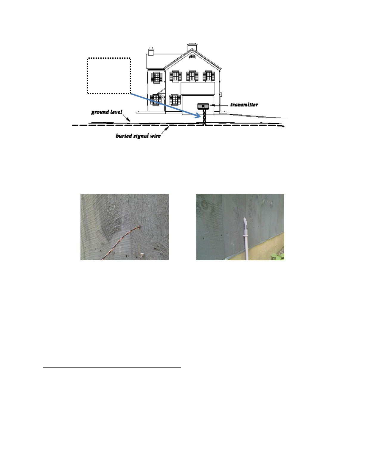
2. Select a dry indoor location, near a grounded 110VAC electric outlet for your
Transmitter installation. This location should offer easy access to the outdoors. A
garage or basement is usually the best location. If you are not sure the intended
outlet is grounded, use a 3-wire circuit analyzer or contact an electrician.
Caution: Never install a system or equipment, or service any equipment, during a
thunderstorm or electrical storm, or when thunder or lightning is in your area.
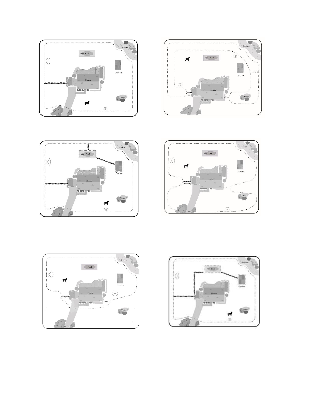
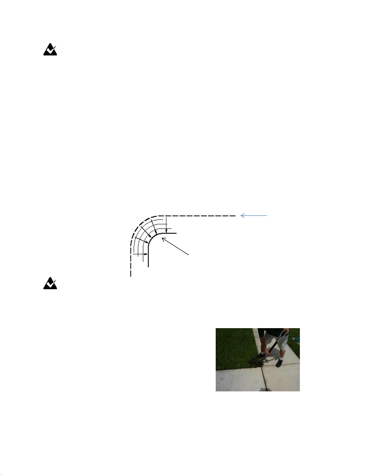
3. Walk your property and identify where you would like to install your Invisible
Fence®Brand perimeter (boundary) wire.
a. Keep in mind that your pet will stop 6-8 ft. from where you install your
perimeter (boundary) wire.
b. Identify any obstacles, structures, and sharp hills/inclines and plan how you
will bury the perimeter (boundary) wire, avoiding injury and damage to
wire.
c. Take advantage of your property’s natural boundaries, such as hedges, tree
lines, or existing fences. These may aid your pet in understanding where his
or her “natural” boundaries will be when the temporary training flags are
removed when training is complete.
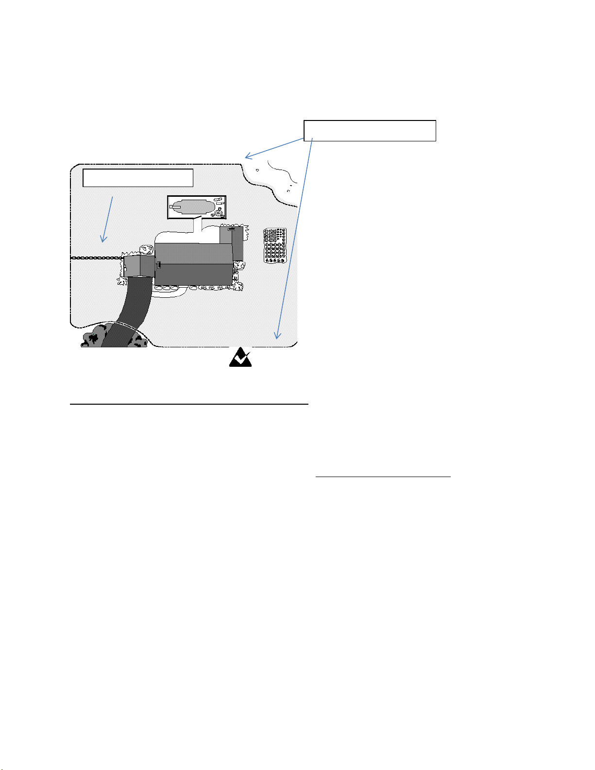
d. Lastly, sketch your design so you can follow the plan and have a reference for
future service needs. Consider areas that should remain “safe” areas such as
bathroom areas, outside kennels, where your pet will exit your house, and
any other areas you wish your pet to pass freely. Make sure when you design

5
the fence you leave 3 to 5 ft. of space between where you will want your pet
to run safely, and where the Computer Collar®unit will begin to tone.
4. At your Asphalt/Concrete/Gravel driveway, select where you will cross the
driveway with the perimeter (boundary) wire. (Remember that your pet will stop 6-
8 ft. back from where you select the driveway crossing).
a. For Asphalt driveways, you will use a chalk snap line to mark a line across
the driveway where you will be scoring a straight line about ½ inch (13mm)
deep, creating a channel for the perimeter (boundary) wire to lie in.
b. For Concrete driveways, find an expansion joint (line in the concrete where
two pads meet) and you will score the expansion joint about ½ inch (13mm)
deep to create a channel for the wire to lie in.
a. For Gravel driveways, using a pix axe, you will create a trench across the
gravel driveway about 4-6 inches deep. You will run the wire through garden
hose, flex tubing or heavy-wall PVC pipe in the trench and then bury it by
hand. The pipe will keep the wire from being cut or abraded by the stones,
particularly under driveways, walkways, and other high traffic areas.
Planning Tip:
Occasionally a client may have to install their Invisible Fence®Brand system in a yard
where their neighbor in the adjacent property has an Invisible Fence®Brand system. You
will want to identify if your neighbor has an Invisible Fence®Brand system, or another pet
containment system, before beginning your installation. Separate systems on adjacent
properties must often be set to operate at different frequencies. One system must be set to
operate at 7 kHz and the other system must be set to operate at 10 kHz on properties
where the loop wires will be closer together than 8 feet (2.4 m). If the operating frequency
of the existing system is 7 kHz, then the system you are going to install should be set to
operate at 10 kHz to keep the neighboring signal fields from interfering with each other.

6
Basic Loop
One loop around the perimeter of the
property. All house exits are protected.
Basic Perimeter Loop with Inner Loops
One loop around the perimeter of the
property. All house exits are protected.
Inner gardens/pools are protected as well.
“Banana” Loop Installation
Double loop around one side of the house.
Only selected house exits are protected.
“Hourglass” Installation
One loop around the perimeter of the
property with loops pinched in on sides. All
house exits are protected, whoever, dog
cannot have access to both front and back
yard at the same time.
Installation Diagrams
Basic Loop with Inner Loops off Transmitter
One loop around the perimeter of the property.
All house exits are protected. Inner gardens or
pools are protected as well from a separate set of
signal wires.
Backyard Only
One loop around the perimeter of the
property. All house exits are protected;
however pet is unable to access the front
yard, only access to the back yard.

7
A typical Invisible Fence®Brand installation
surrounds the entire property.
Invisible Fence®Brand systems only
work when all of the signal field wire,
(including the loop (boundary) wire and
the pre-twisted pair), forms one
continuous closed circuit. The signal must
travel from the transmitter, along the
wire, and back to the transmitter to
complete the circuit.
Installing your Invisible Fence®Brand Wires
If you have underground utilities, they should have been marked out before you began the
installation of your Invisible Fence®Brand wires. The mark-out company will send a
representative to identify underground utilities on your property and place colored flags to
mark found utilities. Wires that cross these areas MUST BE BURIED BY HAND, using care to
ensure you do not accidently cut your existing underground wires (cable, TV, sprinkler,
etc.). Flags will be a specific color depending on the utility it is identifying. Below is a
common color coded chart for you to identify what underground utilities have been
marked out and if there are any that WERE NOT marked properly. If you have any
questions if your property has been cleared by the mark-out company, please call #811 and
speak to a “CALL BEFORE YOU DIG” representative.
Perimeter (Boundary) Wire
Pre-Twisted (neutral) wire

8
Electric
Gas –Oil
Communications
Water
Sewer
Color Code Chart for Marking Utilities:
Running Twisted Pair (neutral) wire
Twisted pair is two lengths of the same signal field loop wire, one carrying the signal out
from the transmitter; the other carrying it back to the transmitter. You can identify these as
the brownish/red wire and a black wire ‘twisted’ together. Where the wires are twisted
together the signal field is cancelled. The twisted pair SHOULD NOT activate your pets
Computer Collar®unit. The twisted pair is used to carry the signal to and from the
transmitter to the loop wire without creating a signal field that will restrain the pet.
Twisted pair is usually run on the most direct route from the signal field loop wire to the
transmitter and is buried the same way as the loop wire. Twisted pair is also used to
connect an extension loop(s) to the primary signal field loop wire.
1. After determining where your ICT Transmitter will be mounted, in your garage,
basement, or utility room, you will need to select where the twisted pair will get to
the outside of the house and connect to the perimeter (boundary) wire. Drill a 3/8”
hole using a hammer Drill and a 3/8” mason bit (or wood if going through wood
siding) in an area that is accessible from the outside of the house so you can easily
pass the twisted pair through the hole to connect to the LP 4200 Surge Protector.
Remember to leave enough slack for the twisted pair inside your utility room,
basement, or garage so you can run the wire to the LP 4200 surge protector.

9
2. Push the twisted pair out the exit hole until it exits that outside of the house. To
protect the twisted pair on the OUTSIDE of your home, you may run the twisted pair
through a length of PVC conduit (we suggest using a 1/2” PVC 90° elbow with a
length of 1/2” PVC as shown below).
3. Bury your twisted pair underground using a spade, gas powered edger, or wire
laying machine from where the twisted exits the house (in the PVC conduit) straight
out to where your perimeter (boundary) wire will begin. (NOTE: this is where the
physical perimeter wire will be buried, not where your pet will stop).
4. Remember to leave some excess slack where the twisted pair will connect to the
perimeter (boundary) wire; this will allow extra wire to work with when connecting
the twisted pair to the perimeter (boundary) wire, in addition to having extra slack
for future service needs.
Running your perimeter (boundary) wire:
Following the steps on the previous pages, you should have planned out where your
perimeter (boundary) wire will be installed and buried. You can mark the location with
flags or cones to follow easily as you work your way around the perimeter of your yard.
(Inside the home)
Where
twisted wire
exits home

10
The perimeter (boundary) wire does not have to be buried to work, but should be
buried to protect the wire from the elements and other entities that may cause the wire to
break.
1. Dig the trench for your perimeter (boundary) wire using the spade or gas powered
edger and push your perimeter (boundary) wire in the trench as you move around
your yard - beginning where your twisted pair ended. If you use a wire laying
machine, secure the wire with a landscaping staples so the wire does not pull up
from the machine moving forward (*always check to be sure the wire is feeding
through the machine and has not been caught and broken on something).
2. Moving around the yard, follow your planned path for the perimeter (boundary)
wire burying the wire around the yard (keep in mind, your pet will stop 6-8ft from
where the wire is buried). Leave some slack where there are large rocks, rock walls,
fences, or other obstacles in your way so you can bury the perimeter (boundary)
wire around/under them.
Make a gradual turn when you bury the loop wire around a corner to help assure a
consistent signal field width along the entire loop.
3. As you approach your driveway
(or a sidewalk) you will need to
use a circular saw or gas powered
cut-off saw to create a groove for
the perimeter (boundary) wire to
lie in. Depending on the driveway
you have (refer to page 5) use the
appropriate method to install the
driveway crossing. Using a spade,
dig away an 8” x 8” square from
both sides of the driveway where
the wire will cross.
Buried Perimeter
(boundary) Wire
Pet’s Signal Field
Starts

11
a. Concrete and Asphalt driveways - Make a straight line using a chalk line to make
the cut easier to follow. Using a mason blade, run the circular saw or gas
powered cut-off saw, along the line making sure to clean out the debris and dust
from the newly cut joint.
Caution: Always wear a respirator or dust mask, steel toe reinforced boots, safety
glasses, and hearing protection when cutting concrete or asphalt.
b. Gravel driveways –To prevent stones from cutting the wire, run it through a
length of PVC pipe, garden hose or flex tubing. To keep water from settling in
the pipe, prop the middle up higher than the ends.
c. After sealing the driveway with the appropriate driveway crossing (or
burying the wire in a gravel driveway), use a broom to sweep the dust
created from the driveway crossing to cover the sealant and create a barrier
so the sealant can cure. The driveway crossing should be dry and cured after
24- 36 hours, but may still be sticky to the touch. You may want to avoid
washing cars in the driveway or running sprinklers for one to two days after
sealing your driveway crossing to allow the driveway sealant to cure
properly. You may want to avoid driving or walking directly on the newly
sealed driveway crossing to prevent transfer on your tires, or on your shoes.

12
d. Continue to bury your perimeter (boundary) wire around your property
until you reach the twisted pair where you started. The below section will
describe how to connect the wires together in compliance with Invisible
Fence®Brand Standards.
Connecting your Invisible Fence®Brand wires
Where your twisted pair and the perimeter (boundary) wires meet, they must be
connected in the proper fashion to ensure the signal makes the loop around the property.
The picture below represents the two sides of the twisted pair; each should be connected to
the perimeter (boundary) wire using the included wire nuts and direct burial splices.
1. Strip about 1 ½ inches of insulation of the end of each wire. Twist the exposed
strands on the end of each wire together to hold them together.
2. Bend the end of each wire to form an L. Twist the end of the first wire around the
end of the second wire once in a clockwise direction. Then twist the end of the
second wire around the first wire once in the opposite direction.
Where Twisted meets Perimeter wire

13
3. Tightly twist the ends of the wires together so that they will maintain good contact
with each other. Hold the two wires parallel to each other and tie an overhand knot
(there should be about 3 inches of space between the knot and the spliced wires.
Place a wire nut over the spliced wires and twist until the wire nut does not spin.
4. Using the provided Direct Burial Splices, place the newly made connection into the
silicone filled splice and make sure the close the splice to protect the connection
from the elements, and bury the connection in the ground.
Installing your Invisible Fence®Brand Transmitter and Components
The transmitter and other components like the LP 4200 Surge Protector, and backup
battery, must be installed in a dry, protected indoor location near a constant source of
110vAC power (outlet). An area on the inside of an exterior wall in a basement, garage, or
utility room is usually the best place. The ideal location would be inside the building at the
point where it will be closest to the signal field loop, easily accessible from the outside, and
where will you will be able have the twisted pair running straight out from the transmitter
to the signal field loop. You’ll typically need an area of two square feet (.6x.6m) to mount
the transmitter and the other indoor components of a system. Look for a location with
a110v outlet, or outlets, which can be used exclusively to provide the power for the system.
Never use an outlet or outlets that can be turned on and off with a switch. Please
make sure you use a dedicated outlet that always has power.

14
LP 4200 Surge Protector
Why install an LP 4200
Lightning strikes within 1-2 miles of your installation can create power surges or spikes,
which may damage your unprotected Invisible Fence®Brand pet containment system.
The Surge Protector is designed to protect your Invisible Fence®Brand pet containment
system from surges or spikes that can reach it via your AC power connection and/or your
buried Boundary Wire.
Install the Surge Protector
Plan the installation as directed by the Operating Guide:
- Use only in dry, protected areas.
- ICT 801 & 802 Systems, install the LP-4200.
STOP: CHECK THE OUTLET YOU PLAN TO
USE BEFORE INSTALLING ANY INVISIBLE
FENCE®BRAND EQUIPMENT TO ENSURE
THE OUTLET IS WORKING!!
The LP-4200 Surge Protector must be plugged into a grounded (3-prong) outlet that is
within 5 feet of the Fence Transmitter. ALWAYS use a grounded (3-prong) outlet to ensure
maximum protection. Cutting or removing the 3rd prong from the Surge Protector or using
a 2-prong to 3-prong outlet converter will render the protector ineffective against surges
or spikes.
If possible, DO NOT use an AC circuit protected with a GFCI (ground fault circuit
interrupter). Both the Surge Protector and the Fence Transmitter will function properly,
but in are cases, nearby lightning strikes may cause the GFCI to trip. Without power, your
dog may be able to escape. You will have to reset the GFCI to restore power to the system.
CAUTION:
• To reduce the risk of electrical shock, disconnect power to the receptacle (outlet) before
installing or removing the Surge Protector. When removing receptacle cover screw, cover
may fall across plug pins or receptacle may become dislodged.
• Use only with a duplex receptacle having a center screw.
• Secure unit in place with screw included with Surge Protector.
Step 1: Turn the power OFF to the outlet that the Surge Protector and Fence Transmitter
will be plugged into.

15
Step 2: We recommend that, if possible,
use the outlet center screw that holds the
cover plate in place to secure the Surge
Protector to the outlet. To do this, tape
the top of the cover plate to the wall, and
then remove the cover plate center screw.
Plug the Surge Protector into the lower
outlet and then secure the cover plate
using the longer screw included with the
protector. The screw is for mechanical
attachment only and does not ground the
protector. Remove the tape and turn ON
the power to the outlet. Be sure to remove
any other protectors and any ground
connectors to the transmitter and the
boundary. The Surge Protector gets its
ground connection from the AC outlet.
Any additional ground connections will
interfere with the protective action and
may also interfere with the operation of
the fence transmitter.
Step 3: Locate the end of the twisted pair that you had run through the wall (there should
be enough slack to reach the location where the LP4200 is installed: Instructions for
running twisted pair, p.8, Step 1).Using the wire cutter/stripper, strip the insulation from
the ends of the twisted pair wire, uncovering approximately 3/8-inch. Insert the stripped
ends of the boundary transmitter wires into the two left red connector holes on the bottom
of the Surge Protector labeled “Loop”. You can secure the excess wire from the exit hole
drilled to the LP 4200 using a stable gun (be sure not to break the insulation of the twisted
wire as this could “bridge” the signal and effect the operation of your Invisible Fence®
Brand system.
Note: There should be one wire in each connector hole. Depress the plastic tab, then insert
the wires and release the tab (see next illustration).

16
Step 4: Determine the length of wire needed to pass from the Surge Protector to the ICT
Fence Transmitter. Measure and cut the length of twisted pair wires, then strip
approximately 3/8-inch of insulation at both ends.
Step 5: Insert the ends of the transmitter wires into the right 2 black connectors at the
bottom of the Surge Protector labeled “Transmitter”.
Note: There should be 1 wire in each connector hole.
Step 6: Insert the opposite stripped ends of the two transmitter wires (Described on Page
17, Step 2 of ICT Transmitter Installation) into the connectors for the appropriate loop on
the ICT Transmitter.
CAUTION: Verify the boundary and transmitter wires are connected to the proper
Surge Protector terminals. Damage to both the Surge Protector and your Fence Transmitter
can occur if connections are reversed.
ICT Transmitter Installation
1. After your LP4200 has been installed, Mount your ICT Transmitter to the wall using
(3) 1 ¼” Drywall screws (or if mounting to a concrete wall, use 1¼” Concrete
screws).

17
ICT 801 or 802 Transmitter
2. As described in the LP 4200 Step 6 (and shown below), insert the opposite stripped
ends of the two transmitter wires into the terminals for the appropriate loop on the
ICT Transmitter. Push in the plastic tabs and insert the wires, one into each port. Let
go of the tabs once the wires have been pushed up in the port and the wires will be
secure into the appropriate Loop terminal.
Push Tabs in and insert wires into
each port.
Let go of Tabs and wires should be
secure.

18
ICT 801 Transmitter Installations:
Setup and Operational Features/Functions of Transmitters
ICT 801 Transmitter Installations:
The ICT 801 is a single loop programmable transmitter designed for installations with up
to 3,000 feet of signal field wire and up to 150 feet of twisted pair wire. The ICT 801 has
one signal field adjustment to increase or decrease the width of the signal field.

19
Loop 1: Loop 1 is always functioning on the ICT 801. (No indicator light on the circuit
board.)
L1 Freq.: Select either 7K or 10K signal for Loop 1. The default setting is 7K.
L1 Signal: Select either Indoor or Outdoor mode for Loop 1. The default setting is Indoor.
Saturation: When lit, indicates Loop 1 transmitter output saturation. Loop saturation
exists when the signal has reached maximum output level, which is caused by excessive
loop size, excessive resistance, or poor connections.
Battery Fault: When lit, indicates that the 12VDC backup battery is either not installed or
not working properly.
Programming the ICT 801 Transmitter
On first time power up, the LED system indicator lights will display the following default
settings.
Once the transmitter has been programmed, the settings will remain in the system
memory. To program the transmitter:
1. Press and hold the S1 button for approximately 4 seconds until:

20
a. For ICT 801: The L1 Freq. LED begins to blink.
b. For ICT 802: The Loop 1 LED begins to blink.
2. Release the S1 button.
3. Momentarily press and release the S2 button to toggle between each setting option.
4. Press and release the S1 button to move to the next setting.
5. Continue until all choices are selected.
6. The cursor LED will stop blinking approximately ten seconds after the buttons are
released, and the transmitter will automatically exit the programming mode.
IMPORTANT: If the transmitter is disconnected from the power source while the
system indicator lights are still blinking, the settings will not be saved to system memory.
Audible Alarm: There is an audible alarm for certain alert conditions (See table below).
Press and release either the S1 or the S2 button on the circuit board to silence the alarm.
The alarm will re-activate on power-up, or when exiting set-up mode (if a failure condition
still exists).
LED Status Indicator Light
Primary Power
Primary power to the unit shall be provided by:
ICT 801 Transmitter: AC Adapter Model RAC00-12612 (Universal transformer)
Setting the Signal Field Width
The signal field is what activates the Computer Collar®unit. The edge of the signal field can
be set to various distances from the signal field wire. The distance from the wire loop to the
edge of the signal field is called the signal field width.
Table of contents
Other Canine Innovations Pet Care Product manuals