Canon JCT-TF5G User manual

2B996-016JA
3CMOS COLOR CAMERA
JCT-TF5G
INSTRUCTION MANUAL
This manual is made from recycled paper.
For Customer Use
Enter below the Serial No.
which is located on the
bottom of the cabinet. Retain
this information for future ref-
erence.
Model No.: JCT-TF5G
Serial No.:

2B996-016JA
2
TABLE OF CONTENTS
REGULATORY INFORMATION ����������������������������������������������������������������������������������������������������������������������4
FCC INFORMATION ..................................................................................................................................4
Following information is only for EU-member states ..................................................................................5
SAFETY PRECAUTIONS��������������������������������������������������������������������������������������������������������������������������������6
1� CAUTIONS ON USE AND INSTALLATION������������������������������������������������������������������������������������������������9
2� COMPONENTS������������������������������������������������������������������������������������������������������������������������������������������9
3� NAMES AND FUNCTIONS ���������������������������������������������������������������������������������������������������������������������� 10
4� CONNECTION������������������������������������������������������������������������������������������������������������������������������������������ 11
4. 1 Standard Connection ....................................................................................................................... 11
4. 2 Cautions on Connection................................................................................................................... 11
4. 3 Connector Pin Assignments............................................................................................................. 11
5� OPERATION���������������������������������������������������������������������������������������������������������������������������������������������12
5. 1 White Balance..................................................................................................................................12
5. 2 Gain .................................................................................................................................................13
5. 3 Shading Correction ..........................................................................................................................13
6� ITEMS CONTROLLED BY THE SCREEN DISPLAY �������������������������������������������������������������������������������14
7� MODE SETTING BY ON SCREEN DISPLAY�������������������������������������������������������������������������������������������15
7. 1 Using the Menus..............................................................................................................................15
7. 2 Menus ..............................................................................................................................................15
( 1 ) SHUTTER (Electronic shutter).........................................................................................................16
(1.1) Changing the setting in MANU mode...................................................................................... 17
(1.2) Changing the setting in SS (synchro. scan) mode................................................................... 18
(1.3) Changing the setting in E.TRG mode ..................................................................................... 19
(1.3.1) Changing the setting in 1P SR mode..........................................................................19
(1.3.2) Changing the setting in PW SR mode ........................................................................20
(1.3.3) Changing the setting in RR mode...............................................................................21
(1.4) Changing each setting in AUTO mode ....................................................................................21
( 2 ) GAIN (Video gain)............................................................................................................................22
(2.1) Changing the setting in GAIN .................................................................................................22
( 3 ) WHT BAL (White balance) ...............................................................................................................23
(3.1) Changing the setting in AWB (Automatic White Balance) mode.............................................23
(3.2) Changing the setting in MANU (Manual) mode ......................................................................23
( 4 ) PROCESS .......................................................................................................................................24
(4.1) Changing gamma correction...................................................................................................24
(4.2) Changing master pedestal......................................................................................................24
(4.3) Changing R pedestal ..............................................................................................................24
(4.4) Changing B pedestal ..............................................................................................................24
(4.5) Changing noise reduction.......................................................................................................24

2B996-016JA
3
( 5 ) SHADING ........................................................................................................................................25
(5.1) Changing V.SHAD. (Vertical Shading) correction mode..........................................................26
(5.2) Changing the manual V.SHAD. (Vertical Shading) correction setting .....................................26
(5.3) Changing C.SHAD. (Corner Shading) correction mode..........................................................26
(5.4) Changing the manual C.SHAD. (Corner Shading) correction setting......................................26
( 6 ) SYNC...............................................................................................................................................27
(6.1) Adjusting horizontal phase......................................................................................................27
( 7 ) OPTION ...........................................................................................................................................27
(7.1) Changing serial communication baud rate..............................................................................27
(7.2) To change the frame rate ........................................................................................................27
( 8 ) Returning to factory settings ............................................................................................................28
7. 3 Synchro. Scan Operation .................................................................................................................28
( 1 ) Setting by 1H ...................................................................................................................................28
( 2 ) Setting by the frame.........................................................................................................................28
7. 4 E. TRG (External trigger) .................................................................................................................29
( 1 ) 1P SR (1 Pulse Trigger SYNC-RESET) ...........................................................................................29
( 2 ) PW SR (Pulse width trigger SYNC-RESET) ....................................................................................30
( 3 ) RR (Reset restart)............................................................................................................................31
7. 5 Partial Scanning...............................................................................................................................32
7. 6 External Sync...................................................................................................................................33
( 1 ) External sync signal polarity ............................................................................................................33
( 2 ) External sync frequency range ........................................................................................................33
( 3 ) Using the unit with external sync signal...........................................................................................33
(3.1) H (horizontal) phase adjustment.............................................................................................33
8� INPUT OUTPUT SIGNAL SPECIFICATIONS������������������������������������������������������������������������������������������34
9� OUTPUT WAVEFORM TIMING CHART���������������������������������������������������������������������������������������������������35
10� BEFORE MAKING A SERVICE CALL���������������������������������������������������������������������������������������������������36
11� SPECIFICATIONS�����������������������������������������������������������������������������������������������������������������������������������37
12� EXTERNAL APPEARANCE DIAGRAM�������������������������������������������������������������������������������������������������38

2B996-016JA
4
REGULATORY INFORMATION
FCC INFORMATION
This device complies with Part 15 of the FCC Rules. Operation is subject to the following two conditions:
(1) This device may not cause harmful interference, and
(2) this device must accept any interference received, including interference that may cause undesired
operation.
NOTE: This equipment has been tested and found to comply with the limits for a Class A digital device,
pursuant to Part 15 of the FCC Rules. These limits are designed to provide reasonable protection against
harmful interference when the equipment is operated in a commercial environment. This equipment
generates, uses, and can radiate radio frequency energy and, if not installed and used in accordance
with the instruction manual, may cause harmful interference to radio communications. Operation of this
equipment in a residential area is likely to cause harmful interference in which case the user will be required
to correct the interference at his own expense.
USER-INSTALLER CAUTION: Your authority to operate this FCC veried equipment could be
voided if you make changes or modications not expressly approved by the party responsible
for compliance to Part 15 of the FCC Rules.

2B996-016JA
5
Following information is only for EU-member states
In residential areas this product may cause radio interference, therefore this product must not
be used in residential areas.
The use of the symbol indicates that this product may not be treated as household
waste.
By ensuring this product is disposed of correctly, you will help prevent potential
negative consequences for the environment and human health, which could other-
wise be caused by inappropriate waste handling of this product. For more detailed
information about the take-back and recycling of this product, please contact your
supplier where you purchased the product or consult.

2B996-016JA
6
SAFETY PRECAUTIONS
Safety icons
This manual contains safety instructions that must be observed in order to avoid potential
hazards that could result in personal injuries, damage to your equipment, or loss of data.
These safety cautions have been classied according to the seriousness of the risk, and the
icons highlight these instructions as follows:
Indicates a potentially hazardous situation which, if not avoided, could result in
death or serious injury.
Indicates a potentially hazardous situation which, if not avoided, may result in
minor or moderate injury.
Indicates a potentially hazardous situation which, if not avoided, may result in
property damage.
Stop operation immediately if any abnormality or defect occurs�
Use during an abnormal condition; such as emitting smoke, burning odors,
damage from dropping, invasion of foreign objects, etc. may result in re and/or
electric shock. Immediately disconnect the power source and contact your dealer.
Avoid installing in a shower room or a bathroom�
This may result in re and/or electric shock.
Do not operate in places where the product may get wet�
This may result in re and/or electric shock.
Do not repair, disassemble and/or modify by yourself�
This may result in fire and/or electric shock. Always be sure to contact your
dealer for internal repair, inspection and cleaning of the product.
Use the specied power supply�
Otherwise, re or electrical shock may occur.
Do not place anything on top of the unit�
Introducing foreign materials, such as metals or liquids into the product may
result in re and/or electrical shock.
Do not put the product on an unstable, slanted or vibrating surface�
If this product is dropped or falls, it may cause serious injury.
Do not touch the product or any connection cables during a thunderstorm�
This may result in electrical shock.

2B996-016JA
7
Note the following instructions when installing�
• Do not cover the product with any material.
• Do not place the product on any confined Inflammable material such as a
carpet or blanket.
• Do not place the product in a narrow space, as this may cause heat to buildup
inside the product.
Failure to follow the above cautions may result in re.
Do not place the product in direct sunshine and/or high temperature�
Temperature build up inside the product may result in re.
Avoid placing in humid, smoky, vaporized or dusty places�
This may result in re and/or electric shock.
Ask your dealer to perform a periodical check and internal cleaning
(approx� once every ve years)�
Dust inside the product may result in fire. For inspection and cleaning cost,
please consult your dealer.
Do not point the lens directly at the sun and/or intense light such as direct
sunlight, etc�
Focusing of the light may cause eye injury and/or re.
Disclaimer
We disclaim any responsibility and shall not be responsible for any damages or losses incurred by
the user in any of the following cases:
1. Fire, earthquake or any other act of God; acts by third parties; misuse by the user, whether inten-
tional or accidental; use under extreme operating conditions.
2. Malfunction or non-function resulting in indirect, additional or consequential damages, including
but not limited to loss of expected income and suspension of business activities.
3. Incorrect use not in compliance with instructions in this instruction manual.
4. Malfunctions resulting from misconnection to other equipment.
5. Repairs or modications made by the user or caused to be made by the user and carried out by
an unauthorized third party.
Notwithstanding the foregoing, CANON MEDICAL SYSTEMS CORPORATION’s liabilities shall not,
in any circumstances, exceed the purchase price of the product.
Copyright and Right of Portrait / Privacy
There may be a conflict with the Copyright Law and other laws when, you, the customer, uses,
displays, distributes, or exhibits an image picked up by the camera without permission from the
copyright holder. Please also note that transfer of an image or le covered by copyright is restricted
to use within the scope permitted by the Copyright Law. In addition, Images taken by the camera
that may reveal the picture or likeness of any individual person may be subject to laws governing
publicity rights of portrait or rights of privacy. You are solely responsible for complying with all appli-
cable laws related to copyright, publicity rights of portrait and rights of privacy.

2B996-016JA
8
Protection of Personal Information
Images taken by the camera that reveal the likeness of an individual person may be considered
personal information. To disclose, exhibit or transmit those images over the internet or otherwise,
consent from such individual person may be required. You are solely responsible to obtain such
consent.
Limitation of Usage
The product is not designed for any “critical applications.” “Critical applications” means life support
systems, exhaust or smoke extraction applications, medical applications, commercial aviation,
mass transit applications, military applications, homeland security applications, nuclear facilities or
systems or any other applications where product failure could lead to injury to persons or loss of
life or catastrophic property damages. Accordingly, CANON MEDICAL SYSTEMS CORPORATION
disclaims any and all liability arising out of the use of the product in any critical applications.

2B996-016JA
9
1� CAUTIONS ON USE AND INSTALLATION
• Handling the unit�
Do not drop, jolt, or vibrate, as this may result
in damage to the unit and may cause problems.
Treat the camera cables carefully to prevent cable
problems, such as breaks in the cable and loose
connections.
• Install the camera in a location free from noise�
If the camera or the cables are located near power
utility lines or a TV, etc. undesirable noise may
appear on the screen. In such a case, try to change
the location of the camera or the cable wiring.
• Operating ambient temperature and humidity�
Do not use the camera in places where temperature
and humidity exceed the specifications. Picture
quality will deteriorate and internal parts may be
damaged.
Be particularly careful when using in places exposed
to direct sunlight. When shooting in hot environments,
depending on the conditions of the object and the
camera (when the gain is increased or at the long
time exposure), noise in the form of vertical strips or
white dots may occur. This is not a malfunction.
• When not using the camera for extended periods
of time�
Switch the control unit off and disconnect the power
supply.
This may result in re and/or electric shock.
• Avoid using or storing the camera in the follow-
ing places:
Places lled with highly ammable and corrosive gas.
Places near gasoline, benzene, or paint thinner.
Places subject to strong vibration.
This may result in re and/or electric shock.
Places containing chemicals (such as pesticides),
rubber or vinyl products for extended periods of time.
This may damage coating and printed letter.
• This product is for indoor use only�
This may result in re and/or electric shock.
• Do not shoot intense light�
If a strong light is imaged, vertical stripes or traverse
bands may appear on the screen but this is not a
failure.
• Moire
A moire pattern is an interference pattern generated
when two repetitive line patterns overlap. This is not
a malfunction. Eliminating the repetitive line patterns,
or aligning the two patterns, will eliminate the moire.
• Handling of the protection cap�
Keep the protection cap away from children as it
poses a choking hazard.
The protection cap protects the image plane when
the lens is removed from the camera; do not discard
the protection cap.
• When cleaning the camera�
Unplug the power source before cleaning. Clean with
a soft dry cloth only. Do not use chemicals or chemi-
cally treated cloths. Chemicals may damage coatings
and printed letters. When cleaning the lens, use lens
cleaning paper.
• Installation without a tripod�
Before installing the camera, make sure that the
location can withstand the total weight of the camera.
If this is not the case, reinforce the area to prevent
the unit from dropping, which may result in damage
to the unit or personal injury.
2� COMPONENTS
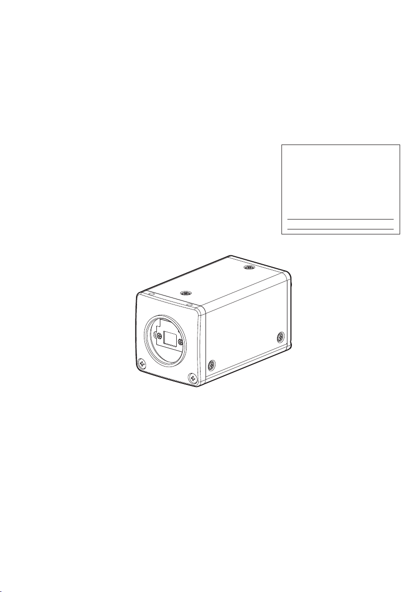
(1) Camera (with protection cap)......................................................................................................... 1
(2) Accessories
(a) Instruction manual ................................................................................................................... 1

2B996-016JA
10
3� NAMES AND FUNCTIONS
[ Bottom ]
10 11
DISP
DC IN 12V
PAGE
MENU DATA
(AWB)
1
9
2
4
6
7
5
8
3
Prism faceplate
DIGITAL terminal
DISP button
PAGE button
[ Rear ][ Front ]
MENU UP button
MENU DOWN button
DATA UP (AWB) button
DATA DOWN button
DC IN 12V terminal
①Prism faceplate The protection cap is attached on the lens mount portion. After removing the cap,
mount the lens. Be careful not to scratch or touch the optical area.
②DISP button Used when switching the display.
③PAGE button Used when switching to the menu and when selecting the menus.
④MENU UP button Select the function to be conrmed or changed on the menu.
⑤MENU DOWN button Select the function to be conrmed or changed on the menu.
⑥DATA UP (AWB) button Changes the value of the function selected by the MENU (UP/DOWN) button. (Also
used when using AWB.)
⑦DATA DOWN button Changes the value of the function selected by the MENU (UP/DOWN) button.
⑧DIGITAL terminal 8-bit RGB, digital signal, and sync signals are output in the Camera Link format.
Trigger signal and external sync signal (HD, VD) are inputs.
Mode switching signal for partial scanning is input.
Accepts serial communication control signals and a DC power input (12V).
⑨DC IN 12V terminal Accept a DC power input (12V).
⑩Mounting holes M3 Used to mount the camera.
⑪Mounting holes M2 Used to mount the camera.

2B996-016JA
11
4� CONNECTION
4� 1 Standard Connection
JCT-TF5G
DC IN 12V
Lens
Cable (not included)
Frame grabber board,
image process
equipment etc.
Monitor
DC power
supply
Less than 4 mm
4� 2 Cautions on Connection
• When connecting the camera cables, be sure to unplug the power source of the camera and the other equip-
ment connected to it.
• We suggest using a C mount lens made for a 3CMOS color camera.
When using another lens, the best camera performance of this camera may not be obtained.
(For example, low resolution may occur, focus may be lost through the range of a zoom lens, and are, ghost
or shading may occur)
Furthermore, in order to avoid damaging the mounting portion of the camera head, use a lens which has
projection dimension from the mounting base of less than 0.157”(4mm).
• The camera may be powered in two ways:
(1) Supplied to the DC IN 12V terminal
• For DC power supply connecting to DC IN 12V terminal, use UL listed and/or CSA approved unground-
ing type AC adaptor with the specications described below.
Power supply voltage : DC12V±10%
Current rating : More than 830 mA
Ripple voltage : Less than 50 mV(p–p)
Connector : HR10A–7P–4S by HIROSE electronics Co. Ltd
Pins 1, 2 : 12V
Pins 3, 4 : GND
• For DC power supply connecting to DC IN 12V terminal, use class II DC power supply approved accord-
ing to EN60950-1 in Europe. or use UL listed and/or CSA approved ungrounded type AC adaptor with
LPS and the specications described below in U.S.A. or Canada.
(2) Supplied to the DIGITAL terminal
• Supply the DC power supply (DC10V-DC13V) to pins 1 and 26 of the cable (sold separately).
• When using PoCL (power over camera link) to power the camera, use a standard PoCL cable.
* Only use one power supply source at a time.
4� 3 Connector Pin Assignments
DC IN 12V DIGITAL Function I/O
1 +12V 1 +12V 14 GND –
2 +12V 2 X0- 15 X0+ O
113
26 14
Connector used:
12226-51000-00
(3M) or equivalent.
3 GND 3 X 1- 16 X1+ O
4 GND 4 X2- 17 X2+ O
Connector used:
HR10A-7P-4PB
(HIROSE electronics
Co. Ltd) or equivalent.
1
2
3
4
5 Xclk- 18 Xclk+ O
6 X3- 19 X3+ O
7 SerTC+ 20 SerTC- Serial communication control (RXD) I
8 SerTFG- 21 SerTFG+ Serial communication control (TXD) O
9 CC1- 22 CC1+ Trigger pulse input I
10 CC2+ 23 CC2- Partial scanning control I
11 CC3- 24 CC3+ External HD input I
12 CC4+ 25 CC4- External VD input I
13 GND 26 +12V –

2B996-016JA
12
5� OPERATION
①Refer to the item “ 4. CONNECTION”, connect each component correctly.
②Turn on the power source of the connected equipment and the camera.
③Point the lens at the object, adjust the lens iris, focus, etc..
④Refer to the item “5.1 White Balance”, to do the adjustment.
⑤Refer to the items “5.2 Gain, 7. MODE SETTING BY ON SCREEN DISPLAY”, select the necessary items.
5� 1 White Balance
For the white balance adjustment of this unit, AWB (Automatic White Balance) and MANU (Manual white balance)
adjustments are provided. To select the desired mode, refer to the items “7.2 (3) WHT BAL (White balance)” .
AWB
(Automatic White Balance)
MANU
(Manual White Balance)
Outline Adjust white balance by displaying the white
object inside the area set by AWB menu and
pressing the [DATA UP] button.
Adjust the white balance manually using the WHT
BAL menu while shooting the white object.
Note When the shutter mode is E.TRG, AWB is not
available.
Adjustment is performed by confirming with a
monitor etc.
①AWB (Automatic white balance)
• Set the MODE to AWB on the WHT BAL menu.
Perform the C.TEMP (color temperature conversion) setting, if necessary.
(Refer to the item “7.2 (3) WHT BAL (White balance)”.)
3200 : Appropriate for shooting under halogen lamps or warm white type lighting.
5600P, 5600C : Appropriate for shooting under sunny daylight type lighting.
• If the index menu/menu is displayed, press the [DISP] button to disable the character display on the menu.
• Shoot a known white object that lls the screen and push [DATA UP] button for approx. 1 second.
• The character AWB blinks on the screen when the AWB starts.
• The character AWB stops blinking when the AWB nishes, and the result is displayed for approx. 1 second.
Result displayed Meaning
AWB OK Automatic white balance adjustment nished correctly.
AWB NG LEVEL
LOW
Automatic white balance adjustment cannot be performed because the video level is too low.
Set the video level propely.
AWB NG LEVEL
HIGH
Automatic white balance adjustment cannot be performed because the video level is too high.
Set the video level propely.
AWB NG
C� TEMP LOW
Automatic white balance adjustment cannot be performed because the color temperature is
too low.
If the C.TEMP is set to 5600P, 5600C set to 3200.
If the message appears with the C.TEMP set to 3200, change the illumination or use a color
temperature conversion lter.
AWB NG
C� TEMP HIGH
Automatic white balance adjustment cannot be performed because the color temperature is
too high.
If the C.TEMP is set to 3200, set to 5600P, 5600C.
If the message appears with the C.TEMP set to 5600P, 5600C, change the illumination or use
the color temperature conversion lter.
AWB NG
NOT AVAILABLE
Automatic white balance adjustment cannot be performed because the shutter speed mode is
in E.TRG mode.
AWB NG Automatic white balance adjustment cannot be performed for other reasons. Such as no white
area is included in an object, etc.

2B996-016JA
13
②MANU (Manual white balance)
• Set the MODE to MANU on the WHT BAL menu.
(Refer to the item “7.2 (3) WHT BAL (white balance)”.)
• Shoot a known white object, adjust the white balance adjusting the levels of R GAIN and B GAIN on the menu,
conrming with a monitor etc.
(Refer to the item “7.2 (3) (3.2) Changing the setting in MANU (Manual) mode.)
5� 2 Gain
When shooting in dark locations, if the image is dark even if the lens iris is open, change the gain (video gain) to get
the proper video level.
For the gain adjustment of the unit, MANU (Manual gain control) and OFF (0 dB) modes are provided. Select the
mode on the GAIN menu. (Refer to the item “7.2 (2) GAIN (Video gain)”.)
①MANU (Manual gain)
Gain adjustment is performed on the GAIN menu. The adjustment range is from 0dB to 18dB in 1dB steps.
(Refer to the item “7.2 (2) (2.1) (a) Changing the gain in MANU mode”.)
②OFF
Gain is xed at 0 dB.
5� 3 Shading Correction
Due to the lens used or the environmental condition, vertical color shading may occur at the top and bottom of the
screen and at the corners. In this case, the shading correction can decrease the color shading. For the shading cor-
rection of the unit, MANU (Manual shading correction) and OFF (no shading correction) modes for V.SHAD. (Vertical
Shading) and C.SHAD. (Corner Shading) are provided. Select the mode on the SHADING menu. (Refer to the “7.2
(5) (5.2) Changing the manual V.SHAD. (Vertical Shading) correction setting” and “7.2 (5) (5.4) Changing the manual
C.SHAD. (Corner Shading) correction setting”.)
①MANU (Manual Shading)
Adjust the correction amount on the SHADING menu by monitoring the output video on a monitor or waveform
monitor.
②OFF
The status is no shading correction.
* The shading correction is effective when the lens iris or zoom ratio is xed� Use the unit by setting V�SHAD�
and C�SHAD� to OFF�

2B996-016JA
14
6� ITEMS CONTROLLED BY THE SCREEN DISPLAY
Item Available selections Preset value
(Factory setting)
Electronic shutter
MODE MANU, SS, E. TRG, AUTO MANU
E. TRG 1P SR, PW SR, RR 1P SR
MANUAL speed
OFF, 1/250s, 1/500s, 1/1000s, 1/2000s, 1/4000s,
1/10000s, 1/24000s (NORMAL) / 1/27000s (FAST),
1/36000s (NORMAL) / 1/39000s (FAST)
OFF
Partial
scanning
(ROI :
Region of
interest)
PA R T - Partial
scanning control OFF, ON, EXT (partial scanning control by CC2) OFF
ROIVS - ROI, Vertical
start position
0,2 to 534 (4 steps each)
(However, total with ROIVW cannot exceed 540.) 0
ROIVW - ROI, Vertical
width
4 to 540 (4 steps each)
(However, total with ROIVS cannot exceed 540.) 540
ROIHS - ROI,
Horizontal start
position
4 to 460 (NORMAL) / 204 (FAST) (4 steps each)
(However, total with ROIVH cannot exceed 720.) 0
ROIHW - ROI,
Horizontal width
260 to 720 (NORMAL) / 516 to 720 (FAST) (4 steps each)
(However, total with ROIHS cannot exceed 720.) 720
Synchro.
scan.
When ROIVW = 540 1H/586H to 571H/586H, OFF, 2FRM to 120FRM OFF
When ROIVW < 540 1H/(ROIVW+42)H to (ROIVW+27)H/(ROIVW+42)H,
OFF, 2FRM to 120FRM OFF
Trigger (1P SR) POSI, NEGA POSI
Trigger (PW SR) POSI, NEGA POSI
1P exposure time 0.03ms~16ms 16 ms
AUTO Level -100~0~100 0
AUTO Peak/Average 00:10~05:05~10:00 05:05
Gain
MODE MANU, OFF OFF
MANU 0dB~18dB 0dB
White
balance
MODE AWB, MANU AWB
Color temperature 3200, 5600P, 5600C 3200
MANUAL R GAIN -100~0~100 0
MANUAL B GAIN -100~0~100 0
Process
GAMMA ON, OFF OFF
Master pedestal -64~0~64 0
R pedestal -64~0~64 0
B pedestal -64~0~64 0
NR ON, OFF OFF
Shading
V. Shading correction mode MANU, OFF MANU
V. Shading manual correction MANU
-128~0~127 0
C. Shading correction mode MANU, OFF MANU
C. Shading manual correction
MANUAL R SIZE
MANUAL R GAIN
MANUAL R POSI
MANUAL B SIZE
MANUAL B GAIN
MANUAL B POSI
0~63
-32~0~31
-32~0~31
0~63
-32~0~31
-32~0~31
0
0
0
0
0
0
Sync
H phase adjustment -100~0~100 0
Option
Baud rate (bps) 9600, 19200 9600
Frame rate NORMAL, FAST NORMAL

2B996-016JA
15
7� MODE SETTING BY ON SCREEN DISPLAY
Various settings can be controlled on the unit by using the on screen menu displayed on the monitor. The contents
once set are memorized even if the power source is turned off, so it is unnecessary to set again when using the unit
next time. When the setting is performed, select the menu of the item to be set. (Use a monitor that can display720 x
540 pixels or higher.)
7� 1 Using the Menus
When the power is turned on, the normal screen showing only the video signal appears. Change the output to each
screen (video signal output, Index menu, and menus) by using the [DISP], [PAGE], [MENU UP], [MENU DOWN],
[DATA UP], and [DATA DOWN] buttons.
* A menu is selected when pushing the [PAGE] button after moving the “ ” on the screen by the [MENU UP], [MENU
DOWN] button while the Index menu is displayed.
AUTO
NR
MANU
PED
E. TRG
RR
E. TRG
1P SR
E. TRG
PW SR
SS
MANU AWB
WHT BAL
ON
MANU
OFF
GAMMA
GAMMA
OFF
MANU
PAGE PAGE PAGEPAGEPAGE
EXT
OUTPUT
INT BAUD
RATE
SHUTTER GAIN PROCESS SYNC
SHADING OPTION
PAGE
PAGE
C.SHAD.
OFF
V.SHAD.
MANU
V.SHAD.
OFF
C.SHAD.
MANU
POWER ON
DISP
PAGE PAGE
DISP DISP
Video signal output
Index menu
Menues
7� 2 Menus
• Select the menu to change the setting by referring to the item “7.1 Using the Menus”.
• When the [MENU UP], [MENU DOWN] buttons are pushed, the “ ” on the screen moves up and down.
Move the “ ” to the item whose setting you wish to change.
Note:
When partial scanning (see page 29) is selected, if you open the content screen or setting screen, the signal
changes to FVAL, LVAL, and DVAL, the same as for all pixels scanning.
When E.TRIG is selected, if you open the content screen or setting screen, the mode changes to internal sync.
When you close the screen display, and return to the video signal screen, operations are done in the set mode.

2B996-016JA
16
( 1 ) SHUTTER (Electronic shutter)
The electronic shutter has four modes; MANU (Manual), SS (Synchro. Scan), E.TRG (External trigger), and AUTO
(Auto Shutter).
Move the “ ” to “MODE” and push [DATA UP], [DATA DOWN] button to select the desired mode among “MANU”, “SS”,
“E.TRG”, and “AUTO”.
MANUAL : It is possible to select the exposure time from nine speed setting; OFF, 1/250s, 1/500s, 1/1000s,
1/2000s, 1/4000s, 1/10000s, 1/24000s (NORMAL) or 1/27000s (FAST), 1/36000s (NORMAL) or
1/39000s (FAST).
When not using the electronic shutter, select OFF.
Note:
When setting a rapid shutter speed, sensitivity degrades according to the speed.
When a discharging light such as uorescent lamp, etc. is used for the illumination, the icker
may be excessive.
SS : Shutter speed can be set by the horizontal scanning time (1H) unit or by the number of frames.
E.TRG : Exposure is performed and images are output by external trigger. E.TRG includes the three modes
described below. (For details of specications, refer to the item “7.4 E.TRG (External trigger)”.)
• 1P SR (1 Pulse Sync Reset)
The charge begins to accumulate to each CMOS pixels after the trigger pulse is received.
Upon completion of accumulation the vertical sync signal is reset and 1 frame images are output.
The exposure/accumulation time can be set from 0.03 to 16 ms. The trigger signal timing can be
set to either the rising or falling edge.
• PW SR (Pulse width trigger Sync Reset)
The charge begins to accumulate to each CMOS pixels after the trigger pulse is received.
Upon completion of accumulation the vertical sync signal is reset and 1 frame images are output.
This is the mode to set the exposure period by the pulse width of the trigger.
The trigger signal polarity can be set to either the positive or negative polarity.
• RR (Reset restart)
Input of an external reset-restart signal permits one screen of information to be output at an arbi-
trary timing.
AUTO : Exposure time is automatically controlled to obtain the specied video level.

2B996-016JA
17
(1�1) Changing the setting in MANU mode
•Shutter mode MANU, SS, E.TRG, AUTO
• Shutter speed setting
• Turning partial scanning on/off
MODE MANU
MANU 250
PART OFF
SHUTTER
<MODE = MANUAL>
Move up down
by pushing
MENU UP, DOWN
Select the desired
value by pushing
DATA UP, DOWN
OFF : Partial scanning is off
ON : Partial scanning is on
You can set the area for partial scanning.
See "7.5 Partial Scanning".
EXT : You can switch between ON and OFF by using
external controls.
OFF, 250(1/250s), 500(1/500s), 1000(1/1000s),
2000(1/2000s), 4000(1/4000s), 10000(1/10000s),
24000(1/24000s(NORMAL)) / 27000(1/27000s(FAST)),
36000(1/36000s(NORMAL)) / 39000(1/39000s(FAST))
* When doing partial scanning, you cannot set a shutter
speed that is slower than one vertical scan interval
determined by the set vertical scan width (ROIVW).
(a) Changing the shutter speed
① Move the “ ” to MANU by pushing [MENU UP], [MENU DOWN] buttons.
② Select the shutter speed by pushing [DATA UP], [DATA DOWN] buttons.
(b) To change the settings for partial scanning
① Move the “ ” to PART by pushing the [MENU UP] and [MENU DOWN] buttons.
② Select the mode you want by pushing the [DATA UP] and [DATA DOWN] buttons. (When ON or EXT is set)
③ Move the “ ” to the setting item you want by pushing the [MENU UP] and [MENU DOWN] buttons.
④ Select the setting values you want by pushing the [DATA UP] and [DATA DOWN] buttons.
* If PART is set to OFF, the setting values for partial scanning are not shown.

2B996-016JA
18
(1�2) Changing the setting in SS (synchro� scan) mode
• Shutter mode MANU, SS, E.TRG, AUTO
• Synchro. scanning setting
refer to the item "7.3 Synchro. Scan Operation".
MODE SS
SS OFF
PART OFF
SHUTTER
<MODE = SS>
Move up down
by pushing
MENU UP, DOWN
Select the desired
value by pushing
DATA UP, DOWN
• Turning partial scanning on/off
OFF : Partial scanning is off
ON : Partial scanning is on
You can set the area for partial scanning.
See "7.5 Partial Scanning".
EXT : You can switch between ON and OFF by using
external controls.
(a) Changing the shutter speed setting
① Move the “ ” to SS by pushing [MENU UP], [MENU DOWN] buttons.
② Select the shutter speed by pushing [DATA UP], [DATA DOWN] buttons.
(b) To change the settings for partial scanning
① Move the “ ” to PART by pushing the [MENU UP] and [MENU DOWN] buttons.
② Select the mode you want by pushing the [DATA UP] and [DATA DOWN] buttons. (When ON or EXT is set)
③ Move the “ ” to the setting item you want by pushing the [MENU UP] and [MENU DOWN] buttons.
④ Select the setting values you want by pushing the [DATA UP] and [DATA DOWN] buttons.
* If PART is set to OFF, the setting values for partial scanning are not shown.
Note:
The slow shutter speed may increase the xed pattern noise and/or the white pixels. This is not a symptom of
malfunction.

2B996-016JA
19
(1�3) Changing the setting in E�TRG mode
The E.TRG has three modes; 1P SR, PW SR, RR.
First move the “ ” to MODE and select E. TRG, then move the “ ” to E.TRG and select the desired E.TRG mode.
(1�3�1) Changing the setting in 1P SR mode
MODE E.TRG
E.TRG 1P SR
TRG.P
EXP. 16ms
POSI
POSI
NEGA
PART OFF
SHUTTER
0.03 ms 0.04 ms 0.4 ms 1 ms 16 ms
<MODE = E.TRG E.TRG = 1P SR>
• E.TRG mode
1P SR, PW SR, RR
• Input trigger pulse setting at 1P SR
• Exposure time setting at 1P SR
• Shutter mode MANU, SS, E.TRG, AUTO
Input trigger pulse : positive polarity
Input trigger pulse : negative polarity
Move up down
by pushing
MENU UP, DOWN
Select the desired
value by pushing
DATA UP, DOWN
0.01 ms
step
0.02 ms
step
0.1 ms
step
1 ms
step
• Turning partial scanning on/off
OFF : Partial scanning is off
ON : Partial scanning is on
You can set the area for partial scanning.
See "7.5 Partial Scanning".
EXT : You can switch between ON and OFF by using
external controls.
(a) Changing the polarity of the input trigger pulse setting
① Move the “ ” to TRG.P by pushing [MENU UP], [MENU DOWN] buttons.
② Select either POSI, NEGA, by pushing [DATA UP], [DATA DOWN] buttons.
(b) Changing 1P SR exposure time setting
① Move the “ ” to EXP. by pushing [MENU UP], [MENU DOWN] buttons.
② Select the exposure time by pushing [DATA UP], [DATA DOWN] buttons.
(c) To change the settings for partial scanning
① Move the “ ” to PART by pushing the [MENU UP] and [MENU DOWN] buttons.
② Select the mode you want by pushing the [DATA UP] and [DATA DOWN] buttons. (When ON or EXT is set)
③ Move the “ ” to the setting item you want by pushing the [MENU UP] and [MENU DOWN] buttons.
④ Select the setting values you want by pushing the [DATA UP] and [DATA DOWN] buttons.
* If PART is set to OFF, the setting values for partial scanning are not shown.

2B996-016JA
20
(1�3�2) Changing the setting in PW SR mode
MODE E.TRG
E.TRG PW SR
TRG.P
PART
OFF
POSI
SHUTTER
<MODE = E.TRG E.TRG = PW SR>
Input trigger pulse : positive polarity
Input trigger pulse : negative polarity
1P SR, PW SR, RR
• Input trigger pulse setting at PW SR
• Shutter mode MANU, SS, E.TRG, AUTO
• E.TRG mode
Move up down
by pushing
MENU UP, DOWN
Select the desired
value by pushing
DATA UP, DOWN
POSI
NEGA
• Turning partial scanning on/off
OFF : Partial scanning is off
ON : Partial scanning is on
You can set the area for partial scanning.
See "7.5 Partial Scanning".
EXT : You can switch between ON and OFF by using
external controls.
(a) Changing the polarity of the input trigger pulse setting
① Move the “ ” to TRG.P by pushing [MENU UP], [MENU DOWN] buttons.
② Select either POSI, NEGA by pushing [DATA UP], [DATA DOWN] buttons.
(b) To change the settings for partial scanning
① Move the “ ” to PART by pushing the [MENU UP] and [MENU DOWN] buttons.
② Select the mode you want by pushing the [DATA UP] and [DATA DOWN] buttons. (When ON or EXT is set)
③ Move the “ ” to the setting item you want by pushing the [MENU UP] and [MENU DOWN] buttons.
④ Select the setting values you want by pushing the [DATA UP] and [DATA DOWN] buttons.
* If PART is set to OFF, the setting values for partial scanning are not shown.
Note:
The longer the storage time with extended exposures, the more visible certain characteristics of CMOS cameras
become: xed pattern noise, white pixels, etc.
Table of contents