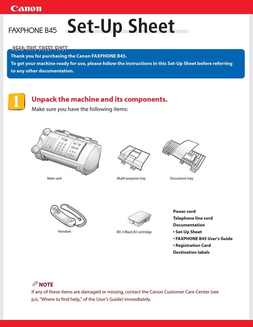
Canon FACSIMILE BASIC 2000 User manual

APR.2000
HY8-53A2-00Z
COPYRIGHT © 2000 CANON INC. FACSIMILE BASIC2000 APR.2000 PRINTED IN JAPAN (IMPRIME AU JAPON)
FACSIMILE
FACSIMILE
BASIC
2000
REVISION 0

Application
This manual has been issued by Canon Inc. to provide information necessary to self-study to tech-
nicians who service facsimile products. This manual covers all localities where the facsimile
products are sold. For this reason, there may be information in this manual that does not apply to
your locality.
The following paragraph does not apply to any countries where such provisions are incon-
sistent with local law.
Trademarks
The product names and company names described in this manual are the registered trademarks of
the individual companies.
Copyright
This manual is copyrighted with all rights reserved. Under the copyright laws, this manual may
not be copied, reproduced or translated into another language, in whole or in part, without the
written consent of Canon Inc.
Copyright © 2000 by Canon Inc.
CANON INC.
Office Imaging Products Technical Support Dept. 3
5-1 Hakusan 7-Chome, Toride-city, Ibaraki 302-8501, Japan
DTP System
All graphics in this manual were produced with Windows Macromedia FreeHand®8.0J
All documents in this manual and all page layouts were created with Windows Adobe Frame
Maker®5.5J

i
1
2
3
4
5
6
ït
çi
PREFACE
This manual describes the general technology and principles of CANON facsimile operation so
that those studying facsimiles for the first time and those already servicing facsimiles can gain a
further understanding of these equipment.
Chapters 1 and 2 describe an overview of telephony and facsimile operation. Chapter 3 onwards
describes the reading section, recording section, communications and electrics in more detail.
Those studying facsimiles for the first time should begin their studies with Chapters 1 and 2.
Those already servicing facsimiles or those who already understand facsimiles to a certain extent
may refer to chapters that meet their particular requirements.
This manual is made up of the following chapters:
Chapter 1: BASIC OF TELEPHONE
Chapter 2: GENERAL DESCRIPTION OF A FACSIMILE
Chapter 3: READING SECTION
Chapter 4: RECORDING SECTION
Chapter 5: G3 FACSIMILE COMMUNICATIONS
Chapter 6: FACSIMILE SYSTEM
APPENDIX
The appendix is followed by a glossary with supplementary explanations of technology that could
not be described in the main text. Refer to this glossary as necessary.
Words colored red in this document are explained in the “GLOSSARY” in the “APPENDIX” of
this document.

ii
CONTENTS
PREFACE.........................................................................................i
CONTENTS.....................................................................................ii
CHAPTER 1 BASIC OF TELEPHONE
INTRODUCTION TO THE TELEPHONE.....................................1-2
Parts of the Telephone..............................................................1-2
Making a Call............................................................................1-3
How do you make a call?..........................................................1-4
Voice Frequencies Carried by the Telephone...........................1-4
STRUCTURE OF A TELEPHONE...............................................1-5
Transmitter (Microphone)..........................................................1-6
Receiver (Speaker)...................................................................1-7
Voice Circuit..............................................................................1-7
Hook Button..............................................................................1-8
Dial............................................................................................1-9
Bell (Speaker).........................................................................1-10
TYPES OF TELEPHONES.........................................................1-11
Dial Telephones......................................................................1-11
Pushbutton Telephones..........................................................1-11
Digital Telephones..................................................................1-12
CIRCUIT DIAGRAM IN THE TELEPHONE................................1-13
Dial Telephones......................................................................1-13
Pushbutton Telephone............................................................1-14
INTRODUCTION TO THE TELEPHONE NETWORK................1-15
Parts of a Telephone Network ................................................1-15
Basic Structure of a Telephone Network System ...................1-19
Nationwide Telephone Network (In case of Japan)................1-20
TELEPHONE EXCHANGES......................................................1-25
Types of Exchanges ...............................................................1-25
The Exchange.........................................................................1-26
CHAPTER 2 GENERAL DESCRIPTION OF A FACSIMILE
WHAT IS A “FACSIMILE?”...........................................................2-2
Established Rules of Communication.......................................2-2
Control Procedure.....................................................................2-2
Facsimile Groups......................................................................2-3

iii
Telephone Lines.......................................................................2-3
Types of ITU-T Recommendations...........................................2-4
How Images are Transmitted ...................................................2-8
STRUCTURE OF A FACSIMILE................................................2-13
Reading Section .....................................................................2-15
Recording Section ..................................................................2-18
MODEM..................................................................................2-21
NCU board (Network Control Unit board)...............................2-22
System Control Section..........................................................2-22
THE FUTURE OF FACSIMILES................................................2-23
Color Facsimiles.....................................................................2-23
LAN-networked Facsimiles.....................................................2-23
Internet Facsimiles .................................................................2-24
CHAPTER 3 READING SECTION
INTRODUCTION..........................................................................3-2
READING METHODS..................................................................3-3
Sheet Reading Method.............................................................3-3
Book Reading Method..............................................................3-4
ADF Type .................................................................................3-4
CONTACT SENSOR..................................................................3-10
Structure of Contact Sensor ...................................................3-10
Features of Contact Sensor....................................................3-10
IMAGE DATA PROCESSOR.....................................................3-14
Various Image Data Processing............................................3-14
CHAPTER 4 RECORDING SECTION
INTRODUCTION..........................................................................4-2
IMAGE DATA PROCESSING SECTION.....................................4-3
Image Area Separation Processing, Smoothing Processing
and Selector .............................................................................4-4
Reproduction Ratio Processing Section...................................4-8
Ink Saving/Toner Saving ........................................................4-11
PAPER FEED SECTION ...........................................................4-12
Pickup Section........................................................................4-12
Feed/Eject Section .................................................................4-17
Detection of Recording Paper Jams.......................................4-19
PRINTING SECTION.................................................................4-24
LBP (LASER Beam Printer)....................................................4-24

iv
Printing by LASER..................................................................4-24
Flow of Printing.......................................................................4-26
Video Control Section/Printer Engine Control Section............4-27
LASER/Scanner Section.........................................................4-32
Printing Process......................................................................4-34
Toner Cartridge.......................................................................4-46
BJ (Bubble Jet) Printer............................................................4-48
Printing by Bubbles.................................................................4-48
Printing Section.......................................................................4-50
Carriage Section.....................................................................4-51
Purge Unit...............................................................................4-56
BJ Cartridge............................................................................4-58
CHAPTER 5 G3 FACSIMILE COMMUNICATIONS
INTRODUCTION..........................................................................5-2
WHAT IS A “G3 FACSIMILE?”.....................................................5-2
G3 FACSIMILE IMAGE TRANSMISSION....................................5-3
Structure of Image Signals........................................................5-3
Transmission Time....................................................................5-5
CODING SCHEMES ....................................................................5-8
Why is Coding Necessary?.......................................................5-8
MH Coding Scheme (One-dimensional Coding Scheme).......5-10
MR Coding Scheme (Two-dimensional Coding Scheme).......5-17
MMR Coding Scheme.............................................................5-28
JBIG Image Compression Encoding Scheme.........................5-29
MODULATION METHOD...........................................................5-45
Modulation and Demodulation................................................5-45
Shift and Modulation Methods ................................................5-46
Modulation Methods up to 9600 bps.......................................5-47
High-speed MODEMs above 14400 bps ................................5-55
V.17 (V.33) MODEM Technology ...........................................5-55
V.34 MODEM Technology......................................................5-73
TRANSMISSION CONTROL PROCEDURES...........................5-89
Outline of Transmission Control Procedures..........................5-89
Signal Types...........................................................................5-90
Basic Transmission Control Procedure...................................5-91
Procedures for Performing Individual Page Control
(Q signals).............................................................................5-100
Training.................................................................................5-102
Method for Detecting Image Signal Transmission Errors .....5-104

v
Option Signals ......................................................................5-106
Structure of Binary Signals...................................................5-107
Example of G3 Procedures ..................................................5-122
ECM Communications..........................................................5-123
CHAPTER 6 FACSIMILE SYSTEM
INTRODUCTION..........................................................................6-2
SCNT BOARD..............................................................................6-3
System Control Section............................................................6-3
Communications Control Section .............................................6-4
Reading Control Section...........................................................6-4
Printer Control Section .............................................................6-4
NCU BOARD................................................................................6-5
Off-hook Detection....................................................................6-6
Formation of DC Loop ..............................................................6-6
Detection of Calling Identification (CI) ......................................6-9
Line Signal Monitor.................................................................6-10
Dial Control.............................................................................6-11
2-wire/4-wire Conversion........................................................6-12
Protective Circuits...................................................................6-12
Telephone Connection Control...............................................6-14
Relay Operations....................................................................6-17
OPCNT BOARD.........................................................................6-18
Detection of Button Input........................................................6-18
LED Lighting Control ..............................................................6-21
Display Indication Control.......................................................6-21
FLOW OF IMAGE SIGNALS......................................................6-22
Transmission ..........................................................................6-22
Reception ...............................................................................6-23
POWER SUPPLY UNIT.............................................................6-24
Switching Regulator................................................................6-24
Configuration of Power Supply Unit on a Facsimile ...............6-31
G4CNT BOARD .........................................................................6-32
APPENDIX TRANSMISSION LINES OF TELEPHONE LINES ..................... A-2
CHARACTERISTICS OF TELEPHONE LINE (ANALOG).......... A-4
Telephone Line Band .............................................................. A-4
Characteristics of Telephone Network Components ............... A-5

vi
Factors of Telephone Line Deterioration..................................A-6
FACSIMILE COMMUNICATION NETWORK SERVICES &
MINIFAX (JAPAN ONLY)..........................................................A-10
F-NET ....................................................................................A-12
Minifax I (MF-I).......................................................................A-16
Minifax II (MF-II).....................................................................A-17
TELEPHONE LINE BAND & SIGNAL SPECTRUM..................A-19
S/N.............................................................................................A-20
POLARITY INVERSION ON EXCHANGE ................................A-21
FACTORS WHICH CAUSE DETERIORATION
IN QUALITY OF FACSIMILE TRANSMISSION........................A-22
Usual Factors.........................................................................A-22
Unusual Factors.....................................................................A-27
Echo.......................................................................................A-28
RATIO, dB, dBm & dBV.............................................................A-35
BINARY SIGNALS TABLE........................................................A-39
MAKER CODES TABLE............................................................A-42
STANDARD DOCUMENT SIZES..............................................A-44
G3 FACSIMILE TRANSMISSION CONTROL PROCEDURES A-45
GLOSSARY...............................................................................A-67
INDEX............................................................................................I-1

CHAPTER 11
2
3
4
5
6
ït
çi
1 BASIC OF TELEPHONE
1. INTRODUCTION TO THE TELEPHONE................................. 1-2
1.1 Parts of the Telephone .................................................... 1-2
1.2 Making a Call .................................................................. 1-3
1.3 How do you make a call?................................................ 1-4
1.4 Voice Frequencies Carried by the Telephone.................. 1-4
2. STRUCTURE OF A TELEPHONE........................................... 1-5
2.1 Transmitter (Microphone) ................................................ 1-6
2.2 Receiver (Speaker) ......................................................... 1-7
2.3 Voice Circuit .................................................................... 1-7
2.4 Hook Button .................................................................... 1-8
2.5 Dial.................................................................................. 1-9
2.6 Bell (Speaker)................................................................ 1-10
3. TYPES OF TELEPHONES ....................................................1-11
3.1 Dial Telephones............................................................. 1-11
3.2 Pushbutton Telephones................................................. 1-11
3.3 Digital Telephones......................................................... 1-12
4. CIRCUIT DIAGRAM IN THE TELEPHONE ........................... 1-13
4.1 Dial Telephones............................................................. 1-13
4.2 Pushbutton Telephone................................................... 1-14
5. INTRODUCTION TO THE TELEPHONE NETWORK............ 1-15
5.1 Parts of a Telephone Network....................................... 1-15
5.2 Basic Structure of a Telephone Network System.......... 1-19
5.3 Nationwide Telephone Network (In case of Japan)....... 1-20
6. TELEPHONE EXCHANGES.................................................. 1-25
6.1 Types of Exchanges...................................................... 1-25
6.2 The Exchange............................................................... 1-26

BASIC OF TELEPHONE
1–2
1. INTRODUCTION TO THE TELEPHONE
You can’t transmit a document unless your facsimile and the receiving fac-
simile are connected over a telephone line. In this section, let’s learn about
the basics of telephones and telephone lines.
1.1 Parts of the Telephone
Very few people know the names of the parts of a telephone even though
they use it every day. Let’s learn the names of the parts on a telephone.
Fig. 1-1 Parts of the Telephone
What we generally refer to as the receiver was in fact the handset.
The “receiver” is the part that we hold against the ear on the handset.
Likewise, the part that we bring near our mouth on the handset is called the
transmitter.
Some people mistakenly refer to the handset as the receiver.
Fig. 1-2 Handset
(Receiver)
(Handset)
(Transmitter)
Hook button
Dial Pushbuttons
Stopper
Telephone body
Receiver
Transmitter
Receiver
Transmitter

1–3
1
2
3
4
5
6
ït
çi
BASIC OF TELEPHONE
1.2 Making a Call
There are names for the party being called and the party making the call.
When we make a call, one of the two parties must first dial to call up the
other party by the bell on its telephone. Making a call in this way, that is,
dialing is called the “outgoing call”, and the call that arrives is called the
“incoming call”.
Fig. 1-3 Telephone Call State (1)
When you lift the handset, the handset is “off-hook”. When you hang up,
the handset is “on-hook”.
These days, some telephones have an on-hook button. For example, even if
the handset is placed on the telephone body, pressing this on-hook button
sets the telephone to the same state (on-hook) as when the handset is
picked up.
Fig. 1-4 Telephone Call State (2)
Outgoing call Incoming call
Off-hookOn-hook

BASIC OF TELEPHONE
1–4
1.3 How do you make a call?
When you call someone, you must take various actions.
Let’s consider each individual action needed for making a call.
(1) You pick up the handset. This means you are making a calling request.
The telephone exchange gets ready to connect you to your party.
(2) The exchange emits the dial tone to indicate it is ready for the called
number.
(3) You dial your party’s number. This is the dialing signal.
(4) When the telephone exchange receives your dialing signal, it attempts
to connect with your party. If your party is free, the exchange will
make the connection, and you will hear a ringing tone.
(5) When the other party picks up the handset, the exchange stops sending
the ringing tone, so that you can have a conversation.
(6) You have your conversation.
(7) You hang up.
When the called number is in use, the calling party hears a busy tone. Even
if the called party hangs up while the caller is listening, the calling party
will still hear the busy tone. So the calling party needs to dial again.
1.4 Voice Frequencies Carried by the Telephone
The human ear can hear sounds with frequencies between 10 Hz and
15,000 to 20,000 Hz. The human voice is composed of many different fre-
quencies. To be able to transmit the full range of hearing over the phone
line would require very high-quality amplifiers and other equipment. Far
more than is practical.
The telephone transmits enough voice frequencies to understand what is
being said; usually between 300 to 3,400 Hz.

1–5
1
2
3
4
5
6
ït
çi
BASIC OF TELEPHONE
2. STRUCTURE OF A TELEPHONE
A telephone consists of a receiver (speaker), a transmitter (microphone), a
voice circuit, a dial, a bell (speaker), and a hook button.
Of these parts, the parts that play the most important roles are the transmit-
ter and the receiver. The transmitter converts human voice to electrical sig-
nals, and the receiver converts the electrical signals from the other party to
voice.
Here, let’s learn about the mechanism of these parts and the roles that they
perform.
Fig. 1-5 Handset
Receiver
Transmitter

BASIC OF TELEPHONE
1–6
2.1 Transmitter (Microphone)
The voice vibrates a diaphragm compressing/releasing carbon powder.
When carbon powder is compressed, its contact resistance decreases.
When the powder is released, its contact resistance increases. So direct
current varies corresponding to the change of pressure (voice). This is
called “voice current”. Recently, a microphone is applied to the transmitter
of the telephone.
Fig. 1-6 Transmitter and Voice Current
Carbon powder
Fixed electrode
Diaphragm
Air vibration
Contact
resistance
Voice current

1–7
1
2
3
4
5
6
ït
çi
BASIC OF TELEPHONE
2.2 Receiver (Speaker)
The receiver acts just like an electromagnet. The receiver creates voice
waves by changing magnetic force, which move a vibrating diaphragm
according to the current strength.
Fig. 1-7 Receiver
2.3 Voice Circuit
When the transmitter and receiver are connected as shown in the Fig. 1-8
to make a voice circuit, voice can be transmitted in both directions along
the two wires.
Fig. 1-8 Two-way Circuit (Two Wires)
Armature
Permanent magnet
Diaphragm
RR
T
T
Calling party Exchange Called party
T:Transmitter
R: Receiver

BASIC OF TELEPHONE
1–8
2.4 Hook Button
When a hook button is closed by picking up a handset, direct current flows
to the telephone circuits.
Fig. 1-9 Hook Button
The purpose of this is twofold (i) so that direct current is made to flow to
the transmitter to provide current for sending voice when the handset is
picked up, and (ii) so that the exchange detects this direct current to recog-
nize that the handset has been picked up.
Fig. 1-10 DC Loop
Picking up a handset is called “making a DC loop”. A DC loop lets the
exchange know that:
(1) The calling party (the party making the call) is ready to call someone.
(2) The called party answered. (The party receiving the call)
(3) The handset is on-hook.
Hook button Hook button
T: Transmitter
R: Receiver
HS: Hook switch
R
T
HS
Exchange Telephone
Direct
current
detector
Detects direct
current. Closed when a handset is
picked up. (Off-hook state)
Direct current (DC) loop

1–9
1
2
3
4
5
6
ït
çi
BASIC OF TELEPHONE
2.5 Dial
Dialling enables an exchange to connect one party to a requested number
according to a dialing signal. “DP” means the Dial pulse contact. The con-
tact is usually closed. When you turn a dial and release it, the contact
opens the same number of times as the number you dialed. (When the
dialed number is 0, the contact opens 10 times.)
When a DC loop is made as shown in the Fig. 1-11 and the dial returns to
its start position after the number “4” is dialed, the DC loop is cut four
times. This is called the “dial pulse”.
Dialing using this dial pulse is called “pulse dial” due to the fact that num-
bers are dialed by this pulse.
Fig. 1-11 Dial Pulse
The exchange selects and calls up the other party by counting the number
of dial pulses.
Dials return to their start position at either of two speeds:
• 10PPS
• 20PPS
PPS (Pulse Per Second) indicates how many dial pulses are generated per
second.
T:Transmitter
R: Receiver
R
TDP: Dial pulse contact
HS (Off-hook state)
HS: Hook switch
DP ON
OFF
1
2
3
4
5
6
7890
Dial return
DP OFF
ON

BASIC OF TELEPHONE
1–10
Here, we have described an example (number of dial pulses = N) where the
number of dial pulses is the same as the dialed number (N). However, in
some countries, the number of dial pulses is sometimes different as fol-
lows:
The number of dial pulses is the dialed number (N) + 1
The number of dial pulses is the dialed number (N) - 1
2.6 Bell (Speaker)
The calling identification (CI) signal from the exchange for notifying that
you have an incoming call is converted to the ring tone and is output.
Recently, a speaker or buzzer is used instead of the bell.
Dialed number 1 2 34567890
Numberofdialpulses23456789101
Dialed number 1 2 34567890
Numberofdialpulses10123456789

1–11
1
2
3
4
5
6
ït
çi
BASIC OF TELEPHONE
3. TYPES OF TELEPHONES
There are three types of telephone: dial telephones and pushbutton tele-
phones that are used on analog lines, and digital telephones that are used
on digital lines.
In this section, let’s learn about these types of telephones.
3.1 Dial Telephones
The type of telephone having a dial as explained earlier in section 2.5 is a
dial telephone.
3.2 Pushbutton Telephones
Pushbutton telephones differ from telephones that are operated by turning
a dial in that buttons are pushed to output dialing signals.
Pushbutton telephones have 12 buttons and have an oscillator inside to
generate seven different frequencies. For example, if you push button 1,
two frequency currents, 697 Hz and 1209 Hz, are sent simultaneously. This
is called DTMF (Dual Tone Multi Frequency), and dialing using this
DTMF is called “tone dial” due to the fact that numbers are dialed by this
tone. Dialing is also referred to as PB (Push Button) due to the fact that
buttons are pushed.
The exchange distinguishes numbers by this DTMF.
Of these 12 buttons, the * and # buttons are special buttons, and are used
for selecting various handy communications services.
Fig. 1-12 Pushbutton Telephone
12
4
7098 65 3
697Hz
1209Hz
Mixed signals
(PB signal)
697Hz
770Hz
852Hz
941Hz
1209Hz 1477Hz
1336Hz

BASIC OF TELEPHONE
1–12
Some pushbutton telephones have a dial selector switch for selecting
between tone dialing (PB) and pulse dialing. With these pushbutton tele-
phones, if the selector switch is set to pulse dialing, the telephone outputs
dial pulses even though the telephone looks like a pushbutton telephone.
3.3 Digital Telephones
Though digital telephones also have 12 buttons just like a pushbutton tele-
phone, the dialing signals are output not as a tone (frequency) but as a code
comprising a combination of digital 0s and 1s. Also, the signals for ringing
the bell on the other party’s telephone are sent as a code comprising a com-
bination of digital 0s and 1s.
This manual suits for next models
1
Table of contents
Other Canon Fax Machine manuals

Canon
Canon B820 User manual

Canon
Canon FP B150 User manual

Canon
Canon LASER CLASS 3170 User manual

Canon
Canon FAX-B140 User manual

Canon
Canon IR3250 User manual

Canon
Canon FAX-L280 User manual

Canon
Canon FAX-L400 User manual

Canon
Canon FAX-B155 User manual

Canon
Canon B155 User manual

Canon
Canon FAX L380S User manual

Canon
Canon FP B140 User manual

Canon
Canon FAX-L350 User manual

Canon
Canon FAX-L400 User manual

Canon
Canon FAX-C855 User manual

Canon
Canon PIXMA MX360 Series Instruction and safety manual

Canon
Canon PIXMA MX922 User manual

Canon
Canon FAXPHONE L170 User guide

Canon
Canon CLC5151 User manual

Canon
Canon MX450 series Setup guide

Canon
Canon FAXPHONE B740 User manual