COPYRIGHT 2003 CANON INC. CANOSCAN 9900F REV.0 FEB. 2003 PRINTED IN JAPAN (IMPRIME AU JAPON)
CONTENTS
I. SPECIFICATIONS ........................... 1-1
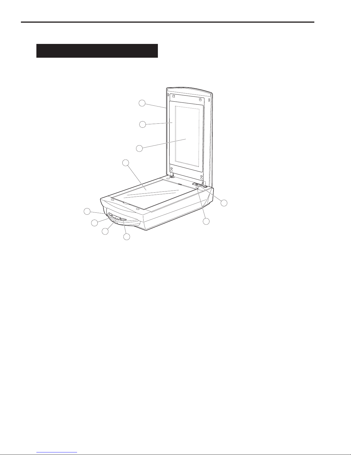
II. PARTS CONFIGURATION ............... 1-2
A. Front View ............................... 1-2
B. Back View ................................ 1-4
III. SETTING UP T E SCANNER ......... 1-5
A. Precautions ............................. 1-5
C APTER 2 : OPERATION AND TIMING
C APTER 1 : GENERAL DESCRIPTIONS
I. BASIC OPERATION ........................ 2-1
A. Functions ................................ 2-1
B. Electrical System .................... 2-2
C. Main PCB Input and Output ... 2-4
D. Document Scanning Sequence
................................................. 2-5
II. OPTICAL SYSTEM ......................... 2-6
A. Outline .................................... 2-6
B. Lamp Lighting Circuit............. 2-7
C. FARE (Film Automatic Retouch-
ing and Enhancement) ............ 2-9
D. Motor Control Circuit ........... 2-11
III. IMAGE PROCESSING ................... 2-12
A. Outline .................................. 2-12
B. Image Processing .................. 2-13
IV. CONTROL SYSTEM...................... 2-20
A. Control System Diagram....... 2-20
B. Main PCB ............................... 2-20
V. INTERFACE .................................. 2-21
A. USB ........................................ 2-21
B. IEEE 1394.............................. 2-24
VI. POWER SUPPLY........................... 2-24
B. Unlocking the Lock Switch .... 1-6
C. Connecting the Cables ............ 1-6
D. Scanning ................................. 1-8
IV. CUSTOMER’S DAILY MAINTENANCE.
............................................... 1-12
C APTER 3 : MEC ANICAL SYSTEM
I. PARTS REPLACEMENT ................. 3-1
A. Precautions ............................. 3-1
II. EXTERNALS .................................. 3-2
A. Removing the Film Adapter Unit .
................................................. 3-2
B. Removing the Top Cover and
Document Glass Unit .............. 3-3
C. Attaching the Top Cover ......... 3-6
D. Removing the Front Panel ...... 3-7
E. Attaching the Front Panel ...3-9
III. PCBs ............................................ 3-11
A. Removing the Main PCB ....... 3-11
IV. OPTICAL SYSTEM ....................... 3-14
A. Removing the Scanning Unit,
Pulley Unit, and Motor Unit .. 3-14
B. Removing the Motor Unit ...... 3-22
C. Attaching the Motor Unit ...... 3-23