6-10KVA Rack-mount UPS User Manual Electromagnetic Compatibility
1
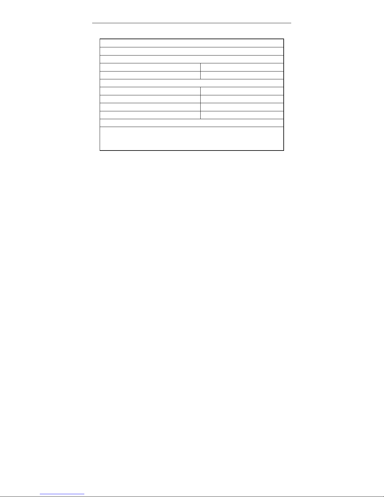
1. ELECTROMAGNETIC COMPATIBILITY
* Safety
IEC/EN 62040-1-1
* EMI
Conducted Emission.........IEC/EN 62040-2 Category C3
Radiated Emission............IEC/EN 62040-2 Category C3
*EMS
ESD..................................IEC/EN 61000-4-2 Level 4
RS....................................IEC/EN 61000-4-3 Level 3
EFT..................................IEC/EN 61000-4-4 Level 4
SURGE............................IEC/EN 61000-4-5 Level 4
Low Frequency Signals..............:IEC/EN 61000-2-2
Warning: This is a product for commercial and industrial application in the second
environment-installation restrictions or additional measures may be needed to
prevent disturbances.
NOTICE:
This is a product for restricted sales distribution to informed partners. Installation restrictions or
additional measures may be needed to prevent radio interference.
Operated the UPS in an indoor enviroment only in an ambient temperature range of
0-40°C(32-104°F). Install it in a clean environment, free from moisture, flammable liquids,
gases and corrosive substance.
This UPS contains no user-serviceable parts except the internal battery pack. The UPS on/off
push buttons do not electrically isolate internal parts. Under no circumstance attempt to gain
access internally, due to the risk of electric shock or burn.
Do not continue to use the UPS if the panel indications are not in accordance with these
operating instructions or the UPS performance alters in use. Refer all fault to your dealer.
Servicing of batteries should be performed or supervised by personnel knowledgeable of
batteries and the precautions. Keep unauthorized personnel away from the batteries. Proper
disposal of batteries is required. Refer to your local laws and regulations for disposal
requirement.
DO NOT CONNECT equipment that could overload the UPS or demand DC current from the
UPS, for example: electric drills, vacuum cleaners, laser printers, hair dryer or any appliance
using half-wave rectification.
Storing magnetic media on top of the UPS may result in data loss or corruption. Turn off and
isolate the UPS before cleaning it. Use only a soft cloth, never liquid or aerosol cleaners.


 Plus Startup manual")


