CAPITOL HY- 6900 User manual

1
HY- 6900
HY-7700
SERVICE MANUAL

2
NOTE
THIS SERVICE MANUAL IS
GUARANTEED EFFECTIVE
FOR SERIAL NO.
ONLY.
CAUTION
DO NOT OPERATE IN REVERSE MODE TO MOVE VESSEL FORWARD
DO NOT OPERATE CONTINUOUSLY IN REVERSE MODE FOR MORE THAN
30 MINUTES AT 75% OF AVAILABLE HORSEPOWER.
DO NOT OPERATE UNIT OVER 180º F (82ºC)
DO NOT OPERATE UNIT WITH HIGH OR LOW OIL PRESSURE
DO NOT ‘WINDMILL’ UNIT IN EVENT OF ENGINE FAILURE (PROP SHAFT
SHOULD BE LOCKED TO PREVENT ‘WINDMILLING’).
DO NOT ATTEMPT FINAL ALIGNMENT OF OUTPUT FLANGE AND PROP
SHAFT COUPLING WHEN VESSEL IS IN DRY-DOCK.
DO NOT SHIFT TRANSMISSION UNLESS ENGINE IS AT IDLE SPEED.
DO NOT USE TRANSMISSION TO SUPPORT REAR OF ENGINE.

3
Table of contents
Section 1. Introduction page
1.1 description 1
1.2 Optional Equipment 1
Section 2. Principles of Operation
2.1Outputrotation 2
2.2ReductionRatio 2
2.3PowerFlow 3
2.4Clutch 3
2.5HydraulicSystem 4
Section 3. Installation and Operation
3.1UncratingandHandling 5
3.2InstallationPreparation 5
3.3InstallationofTransmission 7
3.4AlignmentofOutputCoupling 8
3.5Waterpiping 9
3.6Start-upProcedure 11
3.7OperatingPractices 11
Section 4. Preventive Maintenance
4.1Lubricants 12
4.2RoutineMaintenance 12
4.3MaintenanceScheduleandCheckSheet 13
Section 5. Trouble Shooting
5.1Trouble/RemedyChart 14
Section 6. Repair of External Sub-Assemblies
6.1Oilpump 17
6.2SelectorValve 20
Section 7. Repair of Internal Sub-Assemblies
7.1RemovalofReverseGear 22
7.2Table:ReplacementWearLimits 23
7.3Clutch 24
7.4PinionShaft:RemovalandReassembly 29
7.5OutputGearandRelatedParts 31
7.6HousingParts 32
7.7ReassemblyandinstallationofOutputgearand
relatedparts 33
7.8InstallationofOutputCoupling 35
7.9InstallationofPinionshaftandRelatedparts 35
7.10Post-AssemblyInspection 36
7.11AdditionalAssembly 37
7.12AdapterParts 38
Section 8. Part Information
8.1PartOrderingProcedure 40
8.2UnitRecord 40
8.3SelectorValve 41
8.4Oilpump 42
8.5Clutch 44

4
Table of Contents (Continued)
8.6TransmissionHousingandRelatedParts 46
8.7AdapterGroup 49
8.8PinionShaftandRelatedParts 50
8.9IdlerGearandRelatedParts 50
8.10 Output Gear, Cover and Related Parts 52
8.11 Reduction Gear Selection Chart 54
8.12 Oil Filter 55
8.13 Propeller Coupling Kits 56
8.14 Oil Coolers 57
8.15 Hose and Fitting Kit 58
8.16 Housing and Related Parts (Hy-6900) 59
8.17 Pinion Shaft and Related parts (Hy-6900) 62
8.18 Output Gear and Related Parts (Hy-6900) 64
8.19 Reduction Gear selection Chart (Hy-6900) 66
Section 9. Reference
Installationdrawings
Cross-sectionAssemblydrawings

5

6

7
SECTION 1. INTRODUCTION
The purpose of this manual is to provide
assistance to operation and maintenance
personnel to reduce downtime and obtain
consistent performance.
This service manual contains thorough
installation and operation procedures, steps
for proper maintenance and repair, a trouble
shooting guide for assessing difficulties
promptly, an illustrated parts information
section, and engineering drawings for
fabricating special tools. It should be made
readily available to all those responsible for
the operation or servicing of the reverse
gear.
Performance characteristics and other
details may be obtained from the
engineering department of Capitol Gears,
Inc., St. Paul, Minnesota, U.S.A.
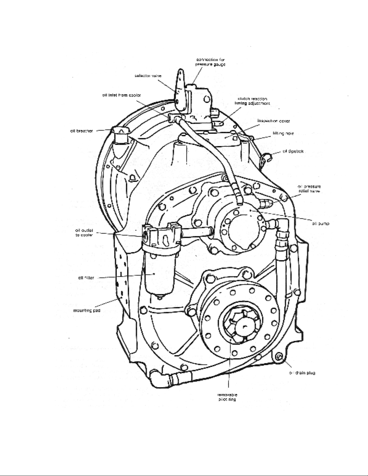
1.1 DESCRIPTION
The Capitol marine transmission is operated
hydraulically. The clutch is activated by high-
pressure oil and the gears, bearings and
clutch discs are lubricated and cooled by
low-pressure oil.
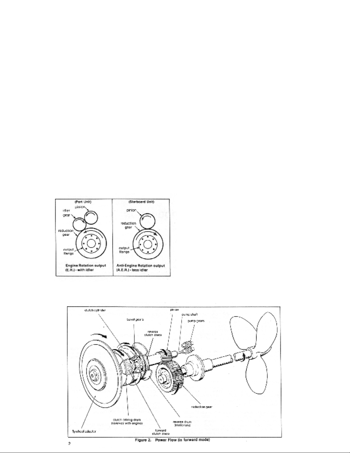
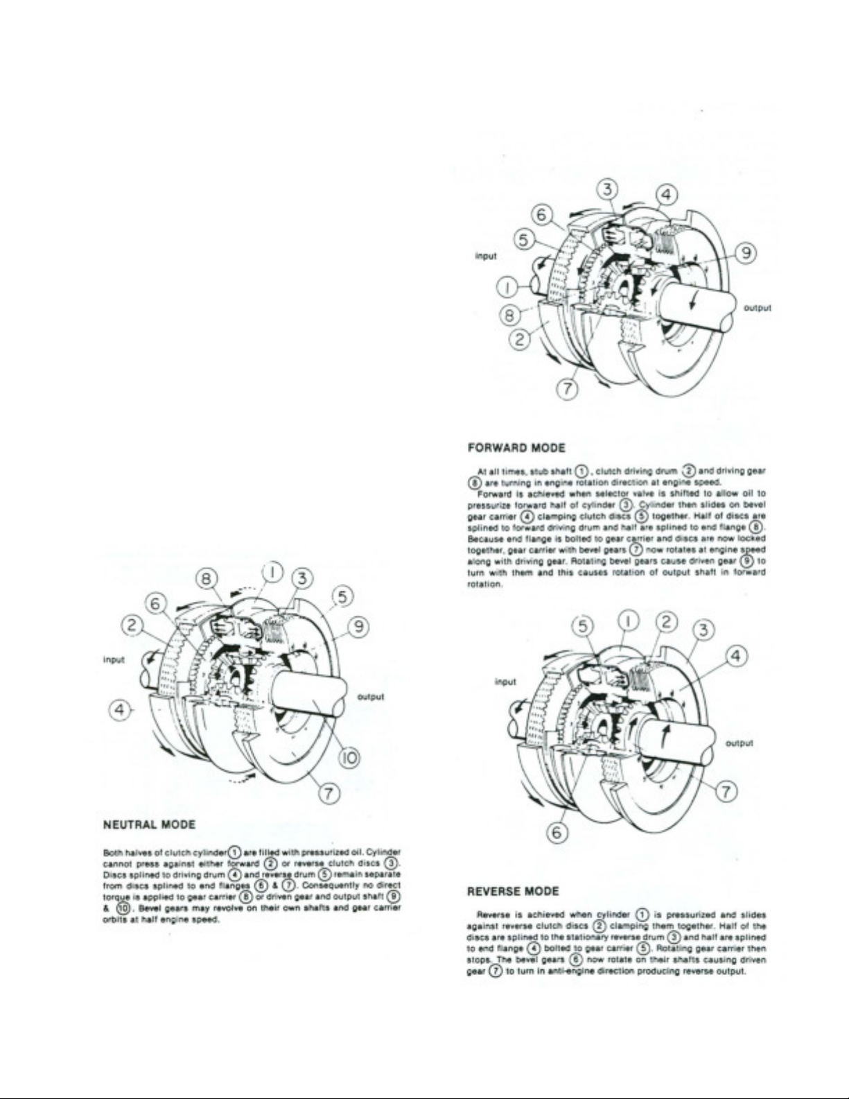
The marine gear consists of six major
groups of parts; adapter group, clutch pack,
oil pump, selector valve, pinion shaft and
reduction gear. The adapter parts vary
according to engine application and include
a flywheel adapter, drive flange, and oil dam
adapter to prevent engine contamination
and driving drum. The clutch pack consists
of reciprocating cylinders, clutch discs and a
planetary bevel gear reversing system. The
oil and pump supplies oil pressure for clutch
engagement and lubrication of bearings,
gears and clutch. The selector valve is used
to obtain forward, neutral or reverse. The
one-piece pinion and shaft drives the output
gear directly or through and intermediary
gear called and idler.
1.2 OPTIONAL EQUIPMENT
OIL COOLER
Various capacity oil coolers for salt or
fresh water are available depending on
engine size and are purchased
optionally. However, oil cooler must be
used with a capitol marine transmission.
HOSE AND FITTING PACKAGE
Kits that include the necessary hose and
fittings are available for use with capitol
oil coolers.
PROP COUPLING KIT
A prop shaft coupling kit is available to
meet most requirements
POWER TAKE-OFF
A one-way clutch may be furnished for
power take-off reduction gears ( HP
PTO series.)
INDEPENDENT MOUNT
For installations where the transmission
is not to be bolted directly to the engine,
a keyed input shaft is available.

8
2.1 OUTPUT ROTATION
The capitol marine gear in forward mode
provides output rotation in the opposite
direction as engine rotation. The marine
gear unit is normally supplied for a right
hand engine (when viewed from the front).
This produces a right hand rotation output of
the prop shaft in forward (When viewed from
the rear of the transmission.) For twin-screw
installations, where two right hand engines
are used, the port unit is furnished with an
idler gear. The idler gear produces, in
forward, an output rotation the same as
engine rotation. Thus the two propellers can
be turning opposite each other in outboard
direction (see diagram below). Note: Engine
rotation transmissions are installed on right
hand engines only.
2.2 REDUCTION RATIO
The reduction ratio is the number of teeth in
the reduction gear compared to the number
of teeth in the pinion, for example, 144 teeth
compared to 36, or 4 to 1. Output speed
then is a product of engine r.p.m and the
reduction ratio, for example 200 r.p.m. X ¼
= 500 r.p.m output speed.
2.3 POWER FLOW
The flywheel adapter, being directly
fastened to the engine flywheel continually
rotates the drive flange assembly, clutch-
driving drum and forward clutch discs at
engine speed.
NEUTRAL
In neutral no direct torque is applied
to clutch and pinion. Consequently
reduction gear and output flange do
not rotate.
FORWARD (See figure 2.)
When forward is selected the entire
clutch becomes locked with the
driving drum and rotates at engine
speed. The clutch drives the pinion
in engine direction and the pinion
drives the reduction gear and output
flange in anti-engine direction at a
speed determined by the reduction
ratio.
SECTION 2. PRINCIPLES OF OPERATION

9
2.3 POWER FLOW (CONT’D.)
REVERSE
When reverse is chosen the clutch is held
stationary to the housing. Engine power is
transferred through the clutch bevel gears and
the pinion is driven in anti-engine rotation at
engine speed. This causes reduction gear and
output flange to rotate in engine direction
(reverse).
2.4 CLUTCH
The clutch assembly is a multiple disc type clutch
activated by a hydraulic mechanism. This
mechanism is formed by a carrier for the bevel
gears and by two cylinders bolted together which
act as the clutch pistons. The movement of the
cylinders is regulated by the selector valve, which
directs pressurized oil to the proper cylinder
depending on the mode selected. The bevel
gears inside the carrier transmit power flow to the
pinion.

10
2.5 HYDRAULIC SYSTEM
is drawn from the sump through a suction
hose and then sent under pressure to a filter
and an oil cooler and the to the selector
valve. The selector valve is used to obtain
forward, neutral or reverse by routing the
high-pressure oil through internal passages
to the clutch. Low-pressure oil is channeled
to cool bearings, gears and clutch discs. An
oil dam keeps the transmission oil within the
transmission housing.
In neutral the ports to both the forward and
reverse sides of the clutch cylinder are
opened and the balanced pressure that
results keeps the clutch cylinder centered
between the forward and reverse clutch
discs. Oil is distributed through the
lubrication system.
When the selector valve is shifted to either
forward or reverse mode high pressure oil is
allowed to flow only to one half of the clutch
cylinder to engage the selected pack. Oil in
the other half of the cylinder is exhausted to
sump. In forward or reverse, oil is also
distributed through the lubrication system.

11
SECTION 3. INSTALLATION AND
OPERATION
NOTE: IMPROPER INSTALLATION AND
ALIGNMENT IS THE GREATEST CAUSE
OF GEAR FAILURE. PLEASE FOLLOW
INSTRUCTIONS CAREFULLY.
3.1 UNCRATING AND HANDLING
Tapped holes have been provided for insertion of
eyebolts to aid in handling the unit. Average
weight of HY-7700 is 1230 lbs.
Check parts for shortage and any damage that
may have occurred (the parts information section
may be used as reference). Report immediately
any shortage or damage to your local distributor,
transfer agent or Capitol Gears.
3.2 INSTALLATION PREPARATION
SPECIALTOOLSREQUIRED
1. Chain hoist or equivalent
2. Straight edge
3. Feeler Gauge
4. Thousandths dial indicator
To insure proper alignment of driving members it
is recommended that engine flywheel housing,
flywheel, oil dam adapter, and stub shaft be dial
indicated to insure trueness.
1. (Fig.3A) Dial indicates the bolt face
of the engine flywheel-housing
flange. Rotate engine flywheel.
Record reading. Face deviation
must not exceed a total indicator
reading of .007 inch.
2. (Fig.3B) Mount indicator with stern
riding on flywheel housing bore as
shown. Rotate flywheel and record
reading. The bore eccentricity must
not exceed a total indicator
reading of .007 inch.
3. (Fig.3c) Mount indicator to flywheel
housing so that stern is on inner face of
flywheel; record deviation of face run
out. It must not exceed a total indicator
reading of .007 inch.
4. (Fig.3D) set stern to ride on the pilot
bore of the engine flywheel as shown.
Record reading. Pilot bore eccentricity
must not exceed a total indicator
reading of .007 inch.
The sum of all readings in steps 1 through 4
must not exceed .007”.
5. Remove the clutch assembly from
the clutch-driving drum and drive
flange assembly (drive flange and
flywheel adapter).
6. Remove clutch-driving drum from
flywheel adapter (Leave drive
flange attached to flywheel
adapter).
7. Thoroughly clean flywheel adapter
to engine flywheel-mating surfaces
and secure flywheel adapter (and
drive flange) to engine flywheel with
capscrews and lock washers.
8. Locate oil dam adapter on engine
flywheel housing with drain slots
down. Secure oil dam tentatively
with capscrews and lockwashers.
NOTE:
Keep all mating surfaces clean. Use
cleaning solvent or diesel fuel.

12
9. Dial oil dam pilot O.D. as shown in figure
4. record reading. Total indicator reading
must not exceed .007 inch.
10. Dial indicates oil dam bolt face as shown
in figure 5. Record reading. Total indicator
reading must not exceed .007 inch
11. Dial indicate stub shaft on chamfer as
shown in figure 6. Record reading. Total
indicator reading must not exceed .007 inch.
The sum of readings in steps 4, 5 and 6
must not exceed .007 inch.
12. Using and adequate hoist, install clutch
on splines of drive flange shaft being careful
that clutch disc teeth enter driving drum
properly. Be sure that the forward end flange
marked “toward engine” is placed toward the
engine flywheel. The forward pack contains
the greater number of clutch discs and must
go toward the engine flywheel. Otherwise
reverse damage to clutch may result.

13
3.3 INSTALLATION OF
TRANSMISSION
1. Apply a small amount of grease to oil
dam adapter and locate gasket.
2. Remove side inspection covers to
facilitate installation.
3. Remove oil pump and oil pump drive
shaft.
4. Using an adequate hoist and hoist
guide (special tool no. 1-90021-0000) lift
transmission into position behind
engine. Ease unit forward over clutch
assembly gently twisting transmission
housing so that discs enter reverse
drum properly without damaging teeth.
A screwdriver may be used through the
side inspection hole to align disc teeth
with the reverse drum.
5. Secure transmission housing to oil dam
adapter with capscrews and
lockwashers.
6. Check clutch end float: insert
screwdriver through side inspection hole
and pry clutch fore and aft. See fig. 20,
page 22. End float should be 1/16” to
3/32”.
7. Turn output coupling over for several
revolutions making sure unit is free to
turn.
8. Replace oil pump drive shaft, gasket
and oil pump. Secure pump with
capscrews and lockwashers.
9. Replace oil pump drive shaft, gasket
and oil pump. Secure pump with cap
screws and lock washers.

14
3.4 ALIGNMENT OF OUTPUT
COUPLING
In marine application, final alignment of
output flange and propeller shaft coupling
must be accomplished when the vessel is
afloat and not in dry-dock, because most
hulls will flex. This is positively necessary to
meet warranty requirements.
Mounting feet on housing permit unit to be
bolted to bed rails, power plant frame,
keelsons, etc.
The distance of the first shaft bearing from
the mating surface of the reverse gear
output coupling is extremely important. To
avoid undue force on the reverse gear
bearings, the propeller shaft bearing should
be located at least twelve and preferably
twenty shaft diameters from the reverse
gear output coupling.
Now align shaft coupling to reverse gear
coupling. Lay a straight edge across the
edges at top and sides to line up couplings.
Do not burr or mar mating surfaces. Insert
feeler gauge between couplings and run it
all around the flange. Clearance should not
be more than .006” at any point. Shim
engine and reverse gear as necessary.
Mounting feet have threaded holes for
jacking screws.
Loosen gear housing to engine housing
bolts and check with feeler gauge. Maximum
variation for SAE “0 housing is .008”; for
SAE #1 housing is .006”.
Tighten four gear housing capscrews at 90º
intervals. Secure engine and gear mounting
feet. Loosen four gear-housing bolts.
Recheck housing and coupling parallelism. If
within limits tighten housing and coupling
bolts.
Be sure transmission is connected to oil
cooler.
NOTE:
The same alignment procedures should be
followed even if a flexible coupling is used. The
most accurate method is to use a non-flexible
spacer of the same size first. Flexible couplings
are used only to dampen noise and vibration and
to correct minor misalignment.
NOTE:
Under no condition is the engine to be supported
by gear housing.

15
3.5 WATER PIPING
To assure proper cooling of the Capitol’s
reverse gear units, connect the cooling
system as indicated on one of the three
diagrams shown. It is extremely important
that the marine gear oil be cooled properly;
the oil cooler must receive an ample supply
of cold water.

16

17
3.6 START-UP PROCEDURE
1. Remove oil breather or top inspection
cover and add recommended oil until
level is up to full mark on dipstick (see
lube chart, p.12). Replace but do not
secure.
2. Install pressure gauge of 300-pound
capacity directly on top of gear or on
bulkhead. Connect gauge to control
valve with hydraulic hose. (Note: Electric
type oil pressure gauges are not
recommended.)
Reverse gear is now ready to start up:
3. Engage starter for approximately 30
seconds, but DO NOT START ENGINE.
This activates pressure pump which pre-
lubricates reverse gear, preventing
premature wear before load is applied.
4. Start engine and check all connections
for leaks.
5. Oil pressure is adjusted at factory for
testing purposes only and it may be
necessary to readjust pressure to the
correct level (200-210 PSI). This should
be set for normal operating speed and
temperature (See fig. 12 below).
6. After unit has been operated a few
minutes, stop engine, check oil level and
add sufficient oil to bring level to full
mark on dipstick. (See lube chart for
capacities). Secure oil breather or
inspection cover
7. Shift several times to insure that all
cylinders, hoses and cooler are full of
oil.
8. Install selector valve cables and shift to
insure valve lever goes into full detent in
all 3 positions; forward, neutral and
reverse.
9. Reverse gear is now ready for sea trials
and final adjustments.
3.7 OPERATING PRACTICES
NOTE:
Normally unit pressure at idle start-up will be
180 PSI, but final adjustment must be made
as noted above.
NOTE:
We strongly recommend installing an interlock control
system, which prevents shifting at other than engine
idle s
p
eed and
g
reatl
y
p
rolon
g
s life of the
g
ear.
CAUTION
1. A Capitol reverse gear should normally not be
shifted unless engine is at idle speed.
2. Reverse gear cannot be operated continuously
in reverse mode for more than 30 minutes at 75%
of available horsepower.
3. In marine application ‘windimilling’ (freewheeling)
is strictly prohibited as extensive internal damage
may result. IN the case of a twin screw application
where only one engine may be used a great deal,
shaft brakes should be installed. ( As an alternative
an auxiliary lube system may be installed).
4. Do not operate unit with high or low oil pressure
or if oil temperature exceeds 180ºF.

18
SECTION 4. PREVENTATIVE
MAINTENANCE
To insure a long service life of the Capitol
Marine gear and to prevent costly and
unexpected failures it is very important that
a regular maintenance schedule be
established and followed.
4.1 LUBRICANTS
Use oil-meeting requirements of MIL-L-
2104B or API SERVICE CLASS. SE/CC.
Series 3 oils are not recommended because
they may shorten clutch life.
Oil Capacity (approximate, depending on cooler,
hoses etc.)
7.5Gallons(28liters)
Bring oil up to full mark on dipstick. Operate unit
in forward and reverse for several minutes. This
will fill cooler, clutch cylinders, pump hoses, etc.
Stop engine and add required oil to return level to
“full” mark on dipstick.
Oil pressure
Operating oil pressure must be at least 200-210
PSI at normal operating speed and maximum
operating temperature.
Pressure Adjustment
See fig. 13, p.11
Oil Temperature
Operating oil temperature range is 100º-150ºF
(38º-66ºC) at control valve. Unit will tolerate
higher temperatures but clutch life may be
shortened considerably.
4.2 ROUTINE MAINTENANCE
Oil Cooler Assembly
Check Zinc pencils in oil cooler ad change if
badly eroded. Check zinc pencils at
approximately every 400 hours of operation.
Check water tubes for obstructions at
approximately every 2000 hours of operation
and flush if necessary.
Oil Filter
The oil filter element should be replaced every
400 hours of operation or at the same time oil is
changed.
Oil Breather
Remove oil breather every 400 hours of
operation or the same time oil is changed. Clean
diesel fuel can be used for flushing.
Pressure Gauge
Periodically check pressure gauge by substituting
a calibrated pressure gauge of known accuracy.
Visual Inspection
At frequent intervals check all oil lines, water
hoses, and connections for leaks. Tighten all
external bolts and connections and visually
inspect external components for wear or damage.
Wear Analysis
At periodic intervals record pressure readings at
idle speed; a gradual decline is normal. Readjust
pressure relief valve to maintain proper operating
pressures. See fig.13, p. 11.
Inspection/ Overhaul interval
A complete inspection of the Capitol marine gear
should be made at least as often as the engine is
overhauled. Parts such as commutator bushings,
oil seals, o-rings, clutch discs, bearings etc.
showing any fatigue or wear should be replaced.
It may be desirable to completely rebuild the
marine gear at this time (see section 7.)
For all normal ambient operating conditions. 30ºF
(-1ºC) to 85ºF (29ºC), We recommend a good
grade, anti-foaming, heavy duty, SAE 30 motor oil.
Where high ambient temperatures are
encountered, over 85ºF (29ºC), it may be
necessary to use SAE 40 motor oil.
Where extremely cold ambient temperatures are
encountered, under 30ºF (-1ºC), it may be
necessary to use SAE 20 motor oil.
CAUTION:
When using SAE 20 motor oil be very attentive to
oil pressures. If proper pressure cannot be
maintained 9200-210 P.S.I) it may be necessary to
use SAE 30 and warm engine and gearbox
thoroughly before engaging clutch. This condition
would only be encountered at extremely low
tem
p
eratures.

19
Engineer____________________
Reverse gear serial no._________
4.3 MAINTENANCE SCHEDULE AND CHECK SHEET Date Service Began___________
INTERVAL
Normal Operation
MAINTENANCE DESCRIPTION RECORD
DAILY
-Check oil level
-Check oil pressure
After first 100 hours
-Change oil and flush sump
Every 400 hours
-Check zinc pencils
-Change oil if contaminated
-Remove and clean oil breather
and suction tube
-Replace filter element
Every 2000 hours
-Check gear backlash (seep. 34)
-Check water tubes in cooler
At engine overhaul
-Inspect clutch and all gearing
and replace as necessary
-Inspect and or overhaul entire
transmission
Frequently
-Check all oil lines and
connections
-Check all external components
-Check all mounting bolts
-Check alignment

20
SECTION 5. TROUBLE SHOOTING
PROBABLE CAU
SYMPTOM PROBABLY CAUSE REMEDY
A. Low oil pressure (at full
operating speed and temperature
1. Faulty pressure gauge
2. Low oil level
3. Clogged filter element
4. Clogged suction tube
5. Clogged parts in selector valve, base
plate or housing
6. Dirt or sludge in transmission
7. Worn pump assembly
8. Incorrectly adjusted pressure relief
valve
9. Oil too hot
10. Worn commutator bushing
11. Incorrect lubricant
12. Scratched clutch cylinders or hard O-ring
in clutch cylinders
1. Check gauge against one of known
accuracy
2. Inspect gaskets, seals, hoses and
fittings for leakage. Pressure test oil
cooler-tubes may leak
3. Replace filter element
4. Remove tube and clean with
solvent. Blow dry
5. Flush clean with solvent and blow dry
6. Remove drain plugs, flush gear with
commercial solvent or diesel fuel. Start
engine; at idle shift gear several times, full
forward to full reverse for 3-5 minutes
maximum. Shut down engine and drain
7. Refer to oil pump section
(Page 17) or fig. 13, p.11.
8. See fig.13 page 11
9. Check heat exchanger system for
clogged oil cooler or hoses.
10. See wear limits chart (p.23)
11. See lube chart (p.12)
12. Replace as necessary (p.25)
B. High Oil pressure (At full operating
speed and temperature) 1. Incorrect adjusted pressure relief valve
2. Inoperable relief plunger in base plate
3. Incorrect oil
4. Cold oil
5. Cold oil at start-up
1. Refer to fig.13 p.11
2. Refer to p.17
3. See lube chart (p.12)
4. Check heat exchanger system
5. Transmission should be pre-heated see
p.11
C. No Oil Pressure
1. Faulty pressure gauge
2. Broken hose
3. No oil in transmission
1.check pressure with gauge of known
accuracy
2. Replace hose. Inspect all hoses
3. Fill with proper oil. See p.12
5.1 TROUBLE/REMEDY CHART
This manual suits for next models
1
Table of contents
Popular DC Drive manuals by other brands

Savant
Savant SHA-B4 00 Series Quick reference guide

Siemens
Siemens SINAMICS S120 Commissioning manual

Schimpf
Schimpf 00-10/30 STEP operating instructions

SycoTec
SycoTec HF Inverter e@syDrive 4624 Short instructions for use

Danfoss
Danfoss VLT HVAC Drive FC 102 operating instructions

WEG
WEG CFW100A01P6S220 Quick installation guide