Caple CM 200 User manual
1
2
INDEX
• Technical Characteristics
• Operating Instruction
• Description of main components
• Warranty and important information
• Spare parts order form
POWER CONSUMPTION (W)
MODEL TANK WATER + COFFEE STEAM WEIGHT Optional
Capacity (KG) Standard
(Litres)
CM 200
230V 120V 100V 12V 230V 120V 100V
50 Hz 60 Hz 60 Hz 24V 50 Hz 60 Hz 60 Hz
1.560 - - - 1.560 - -
3.0 9.5
Coffee/Water
supply
Temperature
Control
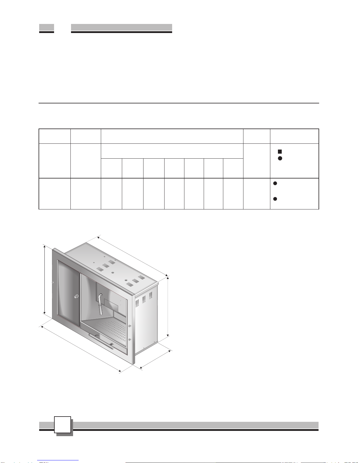
TECHNICAL CHARACTERISTICS
P=253
L= 595
L1= 545
H1= 396
H= 450
OPERATING INSTRUCTIONS
1. INSTALLATION
- Remove the packaging;
- Extract the tank, clean it, insert into position and reintroduce the feed
tubes;
- When assembling do not cover the ventilation grids located on the
side and top of the machine;
- Connect the supply cable;
- Connect the safety drainage system – 14 –
WARNING: ONLY CONNECT THE MACHINE TO ELECTRICAL IN-
STALLATIONS WITH AN EARTH CONNECTION.
Prior to starting the machine for normal coffee making activities, make a
few trial coffees to clean the main elements.
2. FUNCTIONING
2.1 Pre-heating
- Switch on via the main switch – 10 –
- Wait for the red pre-heating indicator light to turn off – 7 –
- If the water level indicating light is on, refill the tank – 8 -
2.2 Coffee dispenser
- Position the coffee cup beneath the pod drawer – 5 –
- Press the centre of drawer to release and open, insert the coffee
pod over the filter and close the drawer;
- Press the coffee dispensing switch – 11 –
- At desired coffee level press the switch again to terminate – 11 –
2.3 Hot Water dispenser
- Position the cup beneath the water nozzle – 4 -
- Press the water supply switch – 12 –
- At desired water level press the switch again to terminate – 12 –
UK
3
2.4 Steam dispenser
- Position the cup beneath the steam nozzle – 3 -
- Press the steam button – 13 –
- Press the steam button to terminate – 13 –
2.5 Water Tank
- Verify the water level and if necessary refill the tank
- Frequently empty and clean the liquid catch tray – 2 -
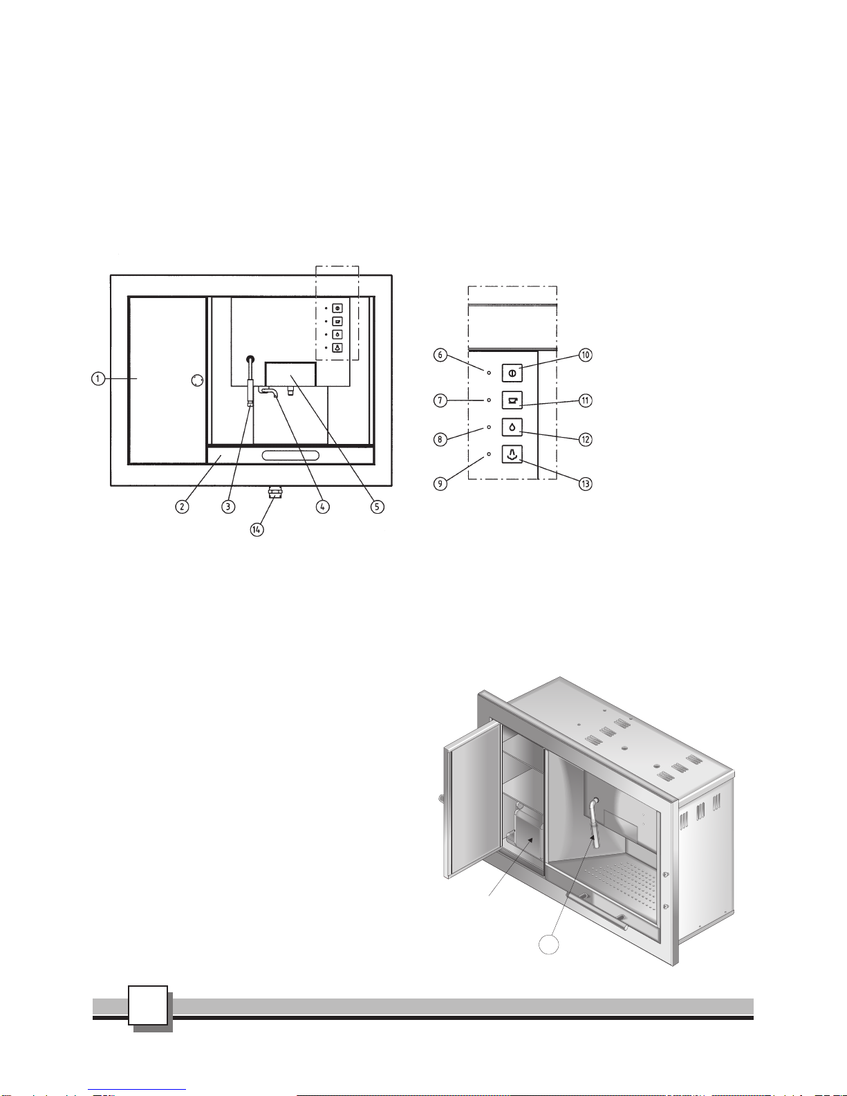
DESCRIPTION OF MAIN COMPONENTS
Detail of Controls / indicator lights Detail of Controls / indicator lights
KEY:
1. Water tank and storage
cabinet
2. Catch tray
3. Steam nozzle
4. Hot water nozzle
5. Pod drawer
6. ON light (Orange)
7. Coffee Group ON light
(Red)
8. Water level indicating light
(Red)
9. Steam indicating light (Red)
10. Main Switch
11. Coffee dispensing switch
12. Water supply switch
13. Steam button
14. Safety drainage tube
3. MAINTENANCE
- Replace the water filter after 4 months of use;
- Replace the seal OR the filter if water leaks occur following 3000
coffees;
- Periodically carry out a complete cleaning cycle of the steam and
coffee groups with the appropriate products for decalcification. (1
packet of citric acid for every two litres of water, following 600
coffees).
fig.1
7 - 9 RED INDICATING LIGHT FOR PRE-HEATING OF COFFEE AND STEAM GROUPS
When the machine is turned on, three indicating lights will turn on:
An orange one to indicate that the machine is connected to the electrical system, two red ones, one each for the pre-heating of the coffee and steam
groups. Although dispensing of coffee is possible during this phase, for optimal results we recommend that you wait until these indicating lights have
switched off. During machine functioning, these lights will periodically light up when the heat exchangers are heating. Should the water tank be empty,
these lights will be off and the machine will begin cooling down until such time as the tank is refilled.
If the water level indicating light is on, open the cabinet door, extract the
water tank and remove the stopper, refill and return to position.
3 - USED
The steam nozzle may be utilised as soon as the red pre-heating light 9
has switched off. This indicates that the correct temperature has been
reached for steam dispensing. Thanks to the characteristics of the water
supply, the steam nozzle will remain cool to the touch when not in use,
heating up only when steam is required.
14 - SAFETY DRAINAGE TUBE
The machine is equipped with a safety drainage connection that must be
connected to the mains water drainage system. On the main structure of
the machine a safety tray is present where any water leaks are collected
as a result of malfunction of the water supply or defects / overflows of
the water tank (see diagram 3).
3
Water tank
fig.2

4
GRAFICA & STAMPA SERIART - Fabriano (AN)
YOUR GUARANTEE
CAPLE guarantees all parts of this product for one year from the date of purchase. During that time, should it become necessary CAPLE engineers will
replace or repair all defective parts free of charge, except for parts subject to fair wear and tear, such as light bulbs.
Parts and the engineers labour costs are chargeable after the first 12 months. To qualify for benefits under the guarantee, you must be able to provide
proof of date of purchase and the appliance must have been supplied, installed and used for domestic purposes only in accordance with CAPLE
instructions.
Consequential losses and accidental damage to the product are not covered by the guarantee.
This guarantee does not affect your statutory or common law rights.
CAPLE cannot be responsible for the results of using this appliance for any other purposes other than those described in these instructions.
Should you require service at any time, please contact the Caple Helpline on 0870 850 8734.
Caple have a nationwide service network of engineers who will respond quickly to your call.
Always replace spare parts with genuine Caple spares.
When ordering parts always quote the model number and serial number of your appliance.
View from rear
Connection
to the water
system (op-
tional)
2 metre supply cable
fig.3
ELECTRICAL CONNECTION
Before fitting the plug into the socket, make sure that:
1. Input voltage matches that indicated on the rating plate posi-
tioned?
2. The socket is compatible with the plug supplied with the ma-
chine without the need to use multiple sockets, adaptors or
extension leads that could cause overheating or burning.
If the socket does not correspond to the supplied plug, replace the
socket with one of a suitable type.
Attention
• The plug must be accessible after installation.
•The appliance must be earthed. Plug the machine into a
socket fitted with an efficient earth connection.
The manufacturer declines all responsibility for damage to persons or property resulting from failure to earth the appliance or from
a defective earth connection. Correct electrical connections guarantee maximum safety.
• If the power cord is damaged, only replace it with an original spare part available from our service department.
• Do not insert/remove the plug from the socket if your hands are wet.
• Remove the plug from the socket by gripping the plug and not the cord.
5 - POD DRAWER
The pod drawer is on runners, when closed it is blocked by a ratchet. To
open it you must first push the front of the drawer to release the trigger
mechanism, then pull the drawer out for pod insertion. To close, push on
the centre until the trigger mechanism catches (see diagram 4).
If it is necessary to dismantle the drawer for cleaning purposes, the
screws behind the hot water supply tube need to be removed.
The supply filter, Illy standard, has been appropriately resized for optimal
machine functioning. If necessary, replace with an identical one.
2 - CATCH TRAY
The catch tray collects the drained liquid from the coffee group and any
cup overflows. For this reason it requires frequent emptying and cleaning
to avoid diffusion of bad odours from stagnant coffee and coffee by-
products.
IMPORTANT:
It is very important that the ventilation grids of the machine remain un-
covered. The grids are positioned to ensure correct internal ventilation
of the machine. During assembly, ensure that they are free of obstruc-
tion.
Ventilation grids
2
5
Table of contents
Other Caple Coffee Maker manuals


