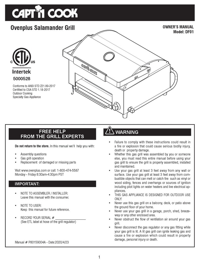
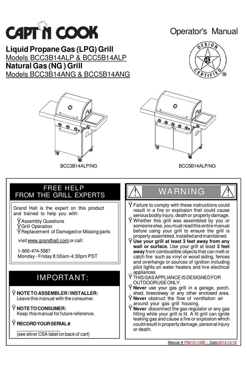
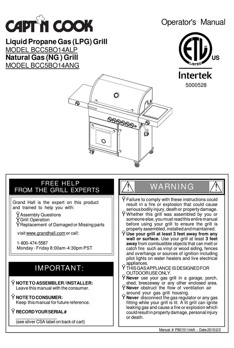
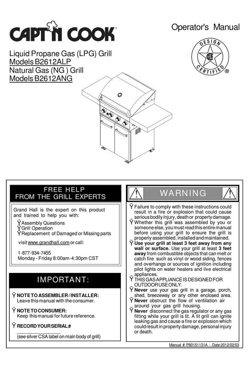
Capt'n Cook B2610ALP User manual

Manual#P80151109C-Date:2010/04/30
Failuretocomplywiththeseinstructionscould
resultinafireorexplosionthatcouldcause
seriousbodilyinjury,deathorpropertydamage.
Whetherthisgrill wasassembled byyouor
someoneelse,youmustreadthisentiremanual
beforeusing yourgrilltoensurethe grillis
properlyassembled,installedandmaintained.
Use yourgrill atleast3feetaway fromany
wall orsurface. Useyourgrill atleast 3feet
awayfromcombustibleobjectsthatcanmeltor
catchfiresuchasvinylorwood siding,fences
and overhangsorsourcesof ignition including
pilotlightson waterheatersand liveelectrical
appliances.
THISGASAPPLIANCEISDESIGNEDFOROUT-
DOORUSEONLY.
Never useyourgasgrillinagarage,porch,
shed,breezewayoranyotherenclosedarea.
Never obstructthe flowofventilation air
around yourgasgrill housing.
Never disconnectthe gasregulatororanygas
fitting while yourgrillislit. Alitgrill canignite
leakinggasandcauseafireorexplosionwhich
couldresultinpropertydamage,personalinjury
ordeath.
Ÿ
Ÿ
Ÿ
Ÿ
Ÿ
Ÿ
WARNING
! !
Ÿ
Grill Information Center:
Ÿ
Ÿ
NOTETOASSEMBLER/INSTALLER:
Leavethismanualwiththeconsumer.
NOTETOCONSUMER:
Keepthismanualforfuturereference.
RECORDYOURSERIAL#
__________________
(seesilverCSAlabelonmainbodyofgrill)
IMPORTANT:
Ÿ
Operator'sManual
FREEHELP
FROMTHEGRILLEXPERTS
Grand Hall isthe expertonthisproduct
andtrained tohelpyouwith:
visitwww.grandhall.comorcall:
1-877-934-7455
Monday-Friday8:00am-4:30pmCST
AssemblyQuestions
GrillOperation
ReplacementofDamagedorMissingparts
Ÿ
Ÿ
Ÿ
LiquidPropaneGas(LPG)Grill
ModelsB2610ALP,B3210ALP
NaturalGas(NG)Grill
ModelsB2610ANG,B3210ANG
B2610ALP/NG B3210ALP/NG

TableofContents
Primary SafetyWarnings............................1-3
Pre-AssemblyInstructions................................3
PartDiagramsand Lists............................4-13
AssemblyInstructions.................................14-20
Use&CareInstructions:
•GasSafetyand LeakTests..............21-23
• NaturalGasConnection............................24
•LightingInstructions...................................25
•Troubleshooting...........................................26
CleaningandMaintenance.......................27-28
CookingGuide..........................................A1-A4
FrequentlyAsked Questions..................A5-A6
RepairProtectionAgreements......Back Cover
2
Donotstoreorusegasolineorother
flammableliquidsorvaporsinthe
vicinityofthisoranyotherappli-
ances.
AnLPcylindernotconnectedfor
useshallnotbestoredinthevicinity
ofthisoranyotherappliance.
1.
2.
•LPGmodelsmustbeusedwithLiquidPropane
Gasandtheregulatorassemblysupplied.Natural
GasmodelsmustbeusedwithNaturalGasonly.
Anyattempttoconvertthe grillfromonefueltype
toanotherisextremelyhazardousandwillvoidthe
warranty.
Keep gasregulatorhoseawayfromhotgrillsurfaces
anddrippinggrease.Avoidunnecessarytwistingof
hose.Visuallyinspecthosepriortoeachuseforcuts,
cracks,excessivewearorotherdamage.Ifthe hose
appearsdamageddonotuse the gasgrill. Call1-
877-934-7455foracertified replacementhose.
CaliforniaProposition65
Combustionbyproductsproduced when using this
productcontainchemicalsknowntotheStateofCalifor-
niatocausecancer,birthdefects,orotherreproductive
harm.
Brasscomponentsonthe grill,suchashosefittings,
propanecylindervalves(soldseparately)andburner
valvestems,containlead whichisknowntothe Stateof
Californiatocausecancer,birthdefects,orotherrepro-
ductive harm.
Neverusecharcoal orlighterfluidinthisgasgrill.
Failuretocomplywiththeseinstructionscouldresultin
agrease fireorexplosionthatcouldcause serious
bodilyinjury,deathorpropertydamage.
The GreaseTray mustbevisuallyinspected beforeeach
grilluse.Removeanygreaseandwash GreaseTray
withamildsoap andwarmwatersolution. Failureto
complywiththeseinstructionscouldresultinagrease
fireorexplosionthatcouldcauseseriousbodilyinjury,
deathorpropertydamage.
•
•
•
•
!
Thisappliance,when installed,mustbe electri-
callygrounded inaccordancewithlocalcodes
or,inthe absenceoflocalcodes,withthe
National Electrical Code,ANSI/NFPA 70, orthe
Canadian Electrical Code,CSA C22.1.
Keep anyelectricalsupplycordand the fuel
supplyhoseawayfromanyheated surfaces.
•
•
WARNING !
DANGER
!!
1.
2.
3.
4.
Ifyousmell gas:
Shutoff gas totheappliance.
Extinguishanyopenflame.
Openlid.
Ifodorcontinues,keepawayfrom
theappliance andimmediatelycall
yourgas supplieroryourfire
department.
WARNING
! !
WARNING
! !

Pre-AssemblyInstructionsForYourSafety
CAUTION
! !
Failuretocomplywiththeseinstructionsmay result
inahazardoussituationwhich,ifnotavoided,may
resultininjury.
Forsafeoperation ensuretheGas ValveAssembly
OrificeisinsidetheBurnerTubebeforeusing your
grill.See figure.IftheOrificeisnotinsidetheBurner
Tube,lighting theBurnermaycause explosion and/
orfireresulting inseriousbodilyinjuryand/or
propertydamage.
METHOD 1:Bend astiff wireorwirecoathanger
intoasmall hook as shownand run thehook
through theBurnerTubeand insidetheBurner
severaltimes toremovedebris.
METHOD 2:Use abottlebrushwithaflexiblehandle
and run thebrushthrough theBurnerTubeand
insidetheBurnerseveraltimes toremoveany
debris.
METHOD 3:Use anairhose toforceairthrough
each BurnerTube.Theforcedairshouldpass
debrisorobstructionsthrough theBurnerand out
thePorts.
TOCLEANBURNERTUBE,
INSERTHOOK
HERE
BurnerTube
9
3
BurnerPort Foot
1.
2.
3.
4. Refertothefigurebelowandperformone ofthese
3cleaningmethods:
CarefullylifteachBurnerupandaway fromtheGas
ValveOrifice.
CheckandcleanBurner/Venturi Tubesfor insectsand
insectnests.Acloggedtubecanlead toafirebeneath
the grill.
Spidersand small insectscanspinwebsand nest
inthegrill BurnerTubes during transitand ware-
housing which canleadtoagas flowobstruction
resulting inafireinand around theBurnerTubes.
Thistypeof"FLASHBACK FIRE"cancause serious
grill damageand createanunsafeoperating con-
dition fortheuser.
Toreduce thechance ofFLASHBACK FIRE
you mustcleantheBurner Tubes as follows
before initialuse. Alsodo thisatleastoncea
monthinsummerand fall orwheneverspidersare
activeinyourarea,and ifyourgrill has notbeen
usedforanextendedperiod oftime.
Remove thescrewsfromtherear ofeachMainBurner
usingaPhillipsHeadScrewdriver.
WARNING: Greasecangetveryhot. Alwayshandlethe Grease
Tray withaflameretardantBBQmitt.Beforeremovingthe
Tray,alwaysbe surethatthegrill hasproperlycooled.Be
awarethatthetraydoes containgrease andbe extremely
carefulwhenremoving thetraytopreventspillage.Failureto
followtheseinstructionscouldcause seriousbodilyinjuryor
propertydamage.
Grill Installation Codes
The installationmustconformwithlocalcodesor,inthe
absence oflocalcodes,witheithertheNationalFuelGas
Code,ANSIZ223.1/NFPA54,NaturalGasandPropane.
InstallationCode,CSAB149.1,orPropaneStorageand
HandlingCode,B149.2.
•
•
•
PRE-ASSEMBLY
Readandperformthefollowingpre-assemblyinstruc-
tions:
ToolsRequiredforAssembly:
protectiveworkgloves
protectiveeyewear
You will needassistancefrom2peopletohandlethe
grillheadand otherlarge,heavyparts.
Openlidofshippingcarton.Removetopsheetof
cardboardandpacking materials.Lay cardboardsheet
onflooranduseasaworksurfacetoprotectfloorand
grillpartsfromscratches.
Youmayslicethecartonfrontcornerswithautilityknife
tolayopenthecarton frontpanel.Thisallowsyou to
raise theLidand remove thecomponentspackedin-
side,makingiteasiertolift.
UsetheHardwareandPartDiagramstoensureall items
areincluded andfreeofdamage.
Donotthrowawaythebagsofhardwarethatarein-
cluded withboxedparts.These arerequiredforassem-
bly.
Donotassembleoroperatethe grillifitappearsdam-
aged.If therearedamagedormissingpartswhenyou
unpacktheshippingboxoryou havequestions during
theassemblyprocess call 1-877-934-7455 M-F8AM-
4:30PMCSTforassistance.
Orifice BurnerTube
GasValveAssembly
PhillipsHeadScrewdriver

4
Hardware Parts List for Model B2610ALP
Hardware Diagramfor Model B2610ALP
PhillipsHeadScrew
3/16"x3/8"
Qty.34
Part#S112G0306A
PhillipsHeadScrew
1/4"x3/8"
Qty.24
Part#S112G0406A
FlangeNut3/16"
Qty.20
Part#S313G0306A
PhillipsHeadScrew
1/4"x2-3/16"
Qty.2
Part#S112G0449A
NylonLockNut
1/4”
Qty.2
Part#S313G0406A
PhillipsHeadScrew
1/4"x1-3/16"
Qty.4
Part#S112G0419A
Plain Washer3/16”
Qty.3
Part#S411G03068
*OneBattery/AA includedin theHardwarePack
PanHeadScrew
3/16"x3/8"
Qty.8
Part#S182G0306A
PhillipsHeadScrew
3/16"x7/8"
Qty.4
Part#S112G0314A
PhillipsHeadScrew
3/16"x3/8"
Qty.3
Part#S112G03061
PhillipsHeadScrew
1/4"x3/8"
Qty.8
Part#S112G04061
FlangeNut3/16"
Qty.3
Part#S313G03061
Wing Bolt1/4"x1/2"
Qty.1
Part#S233G0408A
ForInstalling theTankHolder
Assembly(Alreadyinstalledin
TankHolderAssembly)
DoorHandleBracket
Qty.4
Part#P00217002I
Plain Washer3/16”
Qty.8
Part#S411G0306F
PART#
PARTDESCRIPTION
QTY
PURPOSEOFPART
P06030025A
HardwarePack
1
ForuseinassemblyofB2610ALP
S182G0306A
PanHeadScrew3/16"x3/8"
8
S112G0406A
PhillipsHead Screw1/4"x3/8"
8
S142G0306A
CountersinkFlatHeadScrew3/16"x3/8"
4
Install DoorLower Hinges
S112G0306A
PhillipsHead Screw3/16"x3/8"
4
Install CartSide PanelsontoCartBottomShelf
S112G0406A
PhillipsHead Screw1/4"x3/8"
16
Install Casters
S112G0449A
PhillipsHead Screw1/4"x2-3/16"
2
S313G0406A
NylonLock Nut1/4”
2
S112G0306A
PhillipsHead Screw3/16"x3/8"
4
S313G0306A
FlangeNut 3/16"
4
S112G0306A
PhillipsHead Screw3/16"x3/8"
4
S313G0306A
FlangeNut 3/16"
4
S112G0306A
PhillipsHead Screw3/16"x3/8"
4
S313G0306A
FlangeNut 3/16"
4
S112G0306A
PhillipsHead Screw3/16"x3/8"
2
Install the Door Guide Plateontothe Cart BottomShelf
S112G0306A
PhillipsHead Screw3/16"x3/8"
4
S313G0306A
FlangeNut 3/16"
4
P00217002I
DoorHandleBracket
4
S112G0314A
PhillipsHead Screw3/16"x7/8"
4
S112G0419A
PhillipsHead Screw1/4"x1-3/16"
4
Install the BowltotheCart
S112G0306A
PhillipsHead Screw3/16"x3/8"
4
S313G0306A
FlangeNut 3/16"
4
P05536001Q
HoseHolder/Grill
2
S112G03061
PhillipsHead Screw3/16"x3/8"
3
S313G03061
FlangeNut 3/16"
3
S411G03068
PlainWasher3/16”
3
S112G04061
PhillipsHead Screw1/4"x3/8"
8
S112G0306A
PhillipsHead Screw3/16"x3/8"
8
S411G0306F
PlainWasher3/16”
8
S233G0408A
Wing Bolt 1/4"x1/2"
1
Install BRing tothe TankHolder
Install Caster Seats
Install the Door UpperHinge Bracketsontothe
CartPanelFront
Install the HoseHolders
Install the GreaseTray
Install WeightontoCart BottomShelf
Install the TankHolderBracketstoCart BottomShelf
Install the Cart FrontBrackettoCart Side Panels
Install the Cart PanelReartoCartSide Panels
Install the Side Shelves
Install the Door HandleBracketsontotheDoors
AlreadyinstalledinTankHolderAssembly
CountersinkFlatHead
Screw3/16"x3/8"
Qty.4
Part#S142G0306A
HoseHolder/Grill
Qty.2
Part#P05536001Q

Hardware Parts List for Model B3210ALP
Hardware Diagramfor Model B3210ALP
PhillipsHeadScrew
3/16"x3/8"
Qty.41
Part#S112G0306A
PhillipsHeadScrew
1/4"x3/8"
Qty.24
Part#S112G0406A
FlangeNut3/16"
Qty. 20
Part#S313G0306A
HoseHolder/Grill
Qty.2
Part#P05536001Q
PhillipsHeadScrew
1/4"x2-3/16"
Qty.2
Part#S112G0449A
NylonLockNut
1/4”
Qty.2
Part#S313G0406A
Plain Washer3/16”
Qty.4
Part#S411G03068
PanHeadScrew3/16"x3/8"
Qty.8
Part#S182G0306A
PhillipsHeadScrew
3/16"x7/8"
Qty.4
Part#S112G0314A
FlangeNut3/16"
Qty.4
Part#S313G03061
PhillipsHeadScrew
3/16"x3/8"
Qty.4
Part#S112G03061
5
*OneBattery/AA includedin theHardwarePack
Wing Bolt1/4"x1/2"
Qty.1
Part#S233G0408A
ForInstalling theTankHolder
Assembly(Alreadyinstalledin
TankHolderAssembly)
PhillipsHeadScrew
1/4"x3/8"
Qty.8
Part#S112G04061
DoorHandleBracket
Qty.4
Part#P00217002I
PhillipsHeadScrew
1/4"x1-3/16"
Qty.4
Part#S112G0419A
Plain Washer3/16”
Qty.8
Part#S411G0306F
PART#
PARTDESCRIPTION
QTY
PURPOSEOFPART
P06030023A
HardwarePack
1
For useinassemblyofB3210ALP
S182G0306A
Pan Head Screw3/16"x3/8"
8
S112G0406A
PhillipsHeadScrew1/4"x3/8"
8
S142G0306A
CountersinkFlatHeadScrew3/16"x3/8"
4InstallDoorLower Hinges
S112G0306A
PhillipsHeadScrew3/16"x3/8"
4
InstallCartSide PanelsontoCartBottomShelf
S112G0406A
PhillipsHeadScrew1/4"x3/8"
16
InstallCasters
S112G0449A
PhillipsHeadScrew1/4"x2-3/16"
2
S313G0406A
NylonLock Nut1/4”
2
S112G0306A
PhillipsHeadScrew3/16"x3/8"
4
S313G0306A
Flange Nut3/16"
4
S112G0306A
PhillipsHeadScrew3/16"x3/8"
4
S313G0306A
Flange Nut3/16"
4
S112G0306A
PhillipsHeadScrew3/16"x3/8"
4
S313G0306A
Flange Nut3/16"
4
S112G0306A
PhillipsHeadScrew3/16"x3/8"
2
Installthe Door Guide Plateontothe CartBottomShelf
S112G0306A
PhillipsHeadScrew3/16"x3/8"
4
S313G0306A
Flange Nut3/16"
4
P00217002I
DoorHandleBracket
4
S112G0314A
PhillipsHeadScrew3/16"x7/8"
4
S112G0419A
PhillipsHeadScrew1/4"x1-3/16"
4
Installthe BowltotheCart
S112G0306A
PhillipsHeadScrew3/16"x3/8"
4
S313G0306A
Flange Nut3/16"
4
P05536001Q
HoseHolder/Grill
2
S112G0306A
PhillipsHeadScrew3/16"x3/8"
7
InstallCartPartition Panel
S112G03061
PhillipsHeadScrew3/16"x3/8"
4
S313G03061
Flange Nut3/16"
4
S411G03068
PlainWasher 3/16”
4
S112G04061
PhillipsHeadScrew1/4"x3/8"
8
S112G0306A
PhillipsHeadScrew3/16"x3/8"
8
S411G0306F
PlainWasher 3/16”
8
S233G0408A
Wing Bolt1/4"x1/2"
1
InstallBRing tothe TankHolder
Installthe Cart PanelReartoCartSide Panels
Installthe Side Shelves
Installthe Door HandleBracketsontotheDoors
AlreadyinstalledinTankHolder Assembly
InstallCasterSeats
Installthe Door UpperHinge Bracketsontothe Cart
PanelFront
Installthe HoseHolders
Installthe GreaseTray
InstallWeightontoCart BottomShelf
Installthe TankHolderBracketstoCart BottomShelf
Installthe Cart FrontBracket toCart Side Panels
CountersinkFlat
HeadScrew
3/16"x3/8"
Qty.4
Part#S142G0306A

6*OneBattery/AA includedin theHardwarePack
Hardware Parts List for Model B2610ANG
Hardware Diagramfor Model B2610ANG
PhillipsHeadScrew
3/16"x3/8"
Qty.35
Part#S112G0306A
PhillipsHeadScrew
1/4"x3/8"
Qty.24
Part#S112G0406A
FlangeNut3/16"
Qty.14
Part#S313G0306A
HoseHolder/Grill
Qty.1
Part#P05536001Q
PhillipsHeadScrew
1/4"x2-3/16"
Qty.2
Part#S112G0449A
NylonLockNut
1/4”
Qty.2
Part#S313G0406A
PhillipsHeadScrew
1/4"x1-3/16"
Qty.4
Part#S112G0419A
Plain Washer3/16”
Qty.3
Part#S411G03068
PanHeadScrew
3/16"x3/8"
Qty.8
Part#S182G0306A
PhillipsHeadScrew
3/16"x1/4"
Qty.2
Part#S112G0304A
PhillipsHeadScrew
3/16"x7/8"
Qty.4
Part#S112G0314A
PhillipsHeadScrew
3/16"x3/8"
Qty.3
Part#S112G03061
FlangeNut3/16"
Qty.3
Part#S313G03061
PhillipsHeadScrew
1/4"x3/8"
Qty.8
Part#S112G04061
DoorHandleBracket
Qty.4
Part#P00217002I
Plain Washer3/16”
Qty.8
Part#S411G0306F
PART#
PARTDESCRIPTION
QTY
PURPOSEOFPART
P06030026A
HardwarePack
1
ForuseinassemblyofB2610ANG
S182G0306A
PanHeadScrew3/16"x3/8"
8
S112G0406A
PhillipsHead Screw1/4"x3/8"
8
S142G0306A
CountersinkFlatHead Screw3/16"x3/8"
4Install DoorLowerHinges
S112G0306A
PhillipsHead Screw3/16"x3/8"
4
Install Cart Side PanelsontoCartBottomShelf
S112G0406A
PhillipsHead Screw1/4"x3/8"
16
Install Casters
S112G0449A
PhillipsHead Screw1/4"x2-3/16"
2
S313G0406A
Nylon LockNut1/4”
2
S112G0306A
PhillipsHead Screw3/16"x3/8"
4
S313G0306A
FlangeNut 3/16"
4
S112G0306A
PhillipsHead Screw3/16"x3/8"
4
S313G0306A
FlangeNut 3/16"
4
S112G0306A
PhillipsHead Screw3/16"x3/8"
2
Install the Door Guide PlateontotheCartBottomShelf
S112G0306A
PhillipsHead Screw3/16"x3/8"
4
S313G0306A
FlangeNut 3/16"
4
P00217002I
DoorHandleBracket
4
S112G0314A
PhillipsHead Screw3/16"x7/8"
4
S112G0419A
PhillipsHead Screw1/4"x1-3/16"
4
Install the BowltotheCart
S112G0304A
PhillipsHead Screw3/16"x1/4"
2
Install the NGRegulator
S112G0306A
PhillipsHead Screw3/16"x3/8"
7
Install Cart PartitionPanel
S112G0306A
PhillipsHead Screw3/16"x3/8"
2
S313G0306A
FlangeNut 3/16"
2
P05536001Q
HoseHolder/Grill
1
S112G03061
PhillipsHead Screw3/16"x3/8"
3
S313G03061
FlangeNut 3/16"
3
S411G03068
PlainWasher3/16”
3
S112G04061
PhillipsHead Screw1/4"x3/8"
8
S112G0306A
PhillipsHead Screw3/16"x3/8"
8
S411G0306F
PlainWasher3/16”
8
Install the SideShelves
Install Caster Seats
Install the Door UpperHingeBracketsontothe Cart
PanelFront
Install the HoseHolder
Install the GreaseTray
Install WeightontoCart BottomShelf
Install the Cart FrontBracket toCart Side Panels
Install the Cart PanelReartoCart Side Panels
Install the Door HandleBracketsontothe Doors
CountersinkFlat
HeadScrew
3/16"x3/8"
Qty.4
Part#S142G0306A

7
*OneBattery/AA includedin theHardwarePack
Hardware Parts List for Model B3210ANG
Hardware Diagramfor Model B3210ANG
PhillipsHeadScrew
3/16"x3/8"
Qty. 35
Part#S112G0306A
PhillipsHeadScrew
1/4"x3/8"
Qty.24
Part#S112G0406A
FlangeNut3/16"
Qty.14
Part#S313G0306A
HoseHolder/Grill
Qty.1
Part#P05536001Q
PhillipsHeadScrew
1/4"x2-3/16"
Qty.2
Part#S112G0449A
NylonLockNut
1/4”
Qty.2
Part#S313G0406A
PhillipsHeadScrew
1/4"x1-3/16"
Qty.4
Part#S112G0419A
Plain Washer3/16”
Qty.4
Part#S411G03068
PhillipsHeadScrew
3/16"x7/8"
Qty.4
Part#S112G0314A
PanHeadScrew
3/16"x3/8"
Qty.8
Part#S182G0306A
PhillipsHeadScrew
3/16"x1/4"
Qty.2
Part#S112G0304A
FlangeNut3/16"
Qty.4
Part#S313G03061
PhillipsHeadScrew
3/16"x3/8"
Qty.4
Part#S112G03061
PhillipsHeadScrew
1/4"x3/8"
Qty.8
Part#S112G04061
DoorHandleBracket
Qty.4
Part#P00217002I
Plain Washer3/16”
Qty.8
Part#S411G0306F
PART#
PARTDESCRIPTION
QTY
PURPOSEOFPART
P06030024A
HardwarePack
1
Foruseinassemblyof B3210ANG
S182G0306A
Pan HeadScrew3/16"x3/8"
8
S112G0406A
PhillipsHead Screw1/4"x3/8"
8
S142G0306A
CountersinkFlatHead Screw3/16"x3/8"
4InstallDoor LowerHinges
S112G0306A
PhillipsHead Screw3/16"x3/8"
4
InstallCart SidePanelsontoCart BottomShelf
S112G0406A
PhillipsHead Screw1/4"x3/8"
16
InstallCasters
S112G0449A
PhillipsHead Screw1/4"x2-3/16"
2
S313G0406A
Nylon LockNut1/4”
2
S112G0306A
PhillipsHead Screw3/16"x3/8"
4
S313G0306A
FlangeNut 3/16"
4
S112G0306A
PhillipsHead Screw3/16"x3/8"
4
S313G0306A
FlangeNut 3/16"
4
S112G0306A
PhillipsHead Screw3/16"x3/8"
2
InstalltheDoorGuide PlateontotheCart BottomShelf
S112G0306A
PhillipsHead Screw3/16"x3/8"
4
S313G0306A
FlangeNut 3/16"
4
P00217002I
DoorHandleBracket
4
S112G0314A
PhillipsHead Screw3/16"x7/8"
4
S112G0419A
PhillipsHead Screw1/4"x1-3/16"
4
InstalltheBowltothe Cart
S112G0304A
PhillipsHead Screw3/16"x1/4"
2
InstalltheNGRegulator
S112G0306A
PhillipsHead Screw3/16"x3/8"
7
InstallCart Partition Panel
S112G0306A
PhillipsHead Screw3/16"x3/8"
2
S313G0306A
FlangeNut 3/16"
2
P05536001Q
HoseHolder/Grill
1
S112G03061
PhillipsHead Screw3/16"x3/8"
4
S313G03061
FlangeNut 3/16"
4
S411G03068
PlainWasher3/16”
4
S112G04061
PhillipsHead Screw1/4"x3/8"
8
S112G0306A
PhillipsHead Screw3/16"x3/8"
8
S411G0306F
PlainWasher3/16”
8
InstalltheSide Shelves
InstallCasterSeats
InstalltheDoorUpper Hinge BracketsontotheCart
PanelFront
InstalltheHoseHolder
InstalltheGreaseTray
InstallWeightontoCart BottomShelf
InstalltheCartFront BrackettoCart SidePanels
InstalltheCartPanelRear toCart Side Panels
InstalltheDoorHandleBracketsontothe Doors
CountersinkFlat
HeadScrew
3/16"x3/8"
Qty.4
Part#S142G0306A

PartsDiagramforModelsB2610ALP/NG
8
11
96
4
2
1
5
8
7
3
12
14
15
16
17
19
18
21
20 26
25
27
28
36
37
39 32
24
23
30
53
43
44
45
47
48
49
54a
52
19 17
33
20
60
61 74
75
71
72
70
68
67
59
56
55
57
58
65
66
64 62
73
31
13
38
40
51
50
34
35
41
42
69
10
63
46
54b
29
22 70
71

PartsList forModelsB2610ALP/NG
9
KEY DESCRIPTION PART# QTY
1LidAssembly P001462764 1
2TemperatureGauge P00601071A 1
3 LidHinge P055010204 2
4 LidHandleBracket, Left P03303124A 1
5 LidHandleBracket, Right P03303125A 1
6 LidHandleHeatInsulating Spacer P06802007J 2
7 LidHandle P00218001R 1
8ProtectivePad P055180021I 4
9Cooking Rack/Secondary P01505009E 1
10 TankHolderBracket,Left (LPG) P03304055J 1
11 Cooking Grid, 13" P01615009H 2
12 Burner/Main P02003003B 4
13 FlameTamer/Ceramic,Rear P01804015A 4
14 FlameTamer/Ceramic,Front P01804014A 4
15 FlameTamerRack P01720038F 1
16 Burner BracketAssembly P02209215D 1
17 Side Shelf P011050424 2
18 Side ShelfBracket, Left P033110434 1
19 Side ShelfLock P055010175 4
20 BowlGreaseShield P06902018A 2
21 LightingTube P05507012A 1
22 Door Hinge, Left/Lower P03302037J 1
23 Cart Wind Shield,Rear P06906079E 1
24 BowlRearPanel,Upper P02011073E 1
25 BowlRearPanel P0075809KA 1
26 GreaseHeatShield,Upper P06904051A 1
27 BowlFront Panel P0073888KA 1
28 BowlPanel,Left P0076102KA 1
29 Door Hinge, Right/Lower P03302038J 1
30 BowlPanel,Right P0076202KA 1
31 GasCollectorBoxwithElectrode P026090154 4
32 ElectrodeWireSet P02615175A 1
33 Side ShelfBracket, Right P033110444 1
HoseHolder/Grill (LPG) P05536001Q 2
HoseHolder/Grill (NG) P05536001Q 1
35 Cart BottomShelf(NG) P01001082K 1
36 GasValve/ManifoldExtension P05005392G 1
37 Extension Fitting forManifold P03902029A 1
GasValve/ManifoldAssembly(LPG) Y0060736 1
GasValve/ManifoldAssembly(NG) Y0060738 1
39 Extension Tube P03720003A 1
40 ControlPanelHeatShield P06919003B 1
41 Cart Partision Panel,Right(NG) P07512014D 1
42 Cart Partision PanelBracket, Right(NG) P03303110J 1
43 ControlPanel,Upper P02913441I 1
44 ControlPanel,Lower P02913456I 1
45 ControlKnob Seat P03413033J 4
46 Hose, 12 ft (NG) P03704001A 1
47 ControlKnob/MainBurner P03419633L 4
48 ElectricIgnitor, 4-Port P02502244C 1
49 ElectricIgnitor Protector P03328048Q 1
50 RegulatorwithHoseAssembly(NG) P03614007A 1
34
38

PartsList forModelsB2610ALP/NG
10
KEY DESCRIPTION PART# QTY
51 RegulatorwithHose(LPG) P03601040A 1
52 Door Assembly,Right P04303051D 1
53 LightingStick P05313025B 1
54a GreaseTray P02706404A 1
54b GreaseTrayHandle P0272008H4 1
55 BowlBracket, Left P01301014D 1
56 Cart Bracket, Front P03305074J 1
57 Door Hinge Bracket, UpperLeft P03302014J 1
58 Cart Side Panel,Left P07617048E 1
59 Door Magnet P05523004K 4
60 Cart Panel/Rear P07702119E 1
61 Weight P05344003Q 1
62 Door HandleInsulatingSpacer P06801023G 4
63 TankHolderBracket,Right(LPG) P03304056J 1
64 Door Assembly,Left P04302051D 1
65 Door HandleBracket P00217002I 4
66 Door Handle P00218003R 2
67 Cart BottomShelf(LPG) P01001081K 1
68 Door Guide Plate P05510024Q 1
69 TankHolderAssembly(LPG) P05358003L 1
70 Caster Seat,Left Front/RightRear P03305079J 2
71 Caster Seat,Right Front/LeftRear P03305078J 2
72 Caster, 2.5"withBrake P05110006D 4
73 Door Hinge Bracket, UpperRight P03302015J 1
74 BowlBracket, Right P01302014D 1
75 Cart Side Panel,Right P07618049E 1
HardwarePack(LPG) P06030025A 1
HardwarePack(NG) P06030026A 1
Operator'sManual P80151109B 1

11
PartsDiagramforModelsB3210ALP/NG
11
10
96
4
2
1
5
8
7
3
12
14
15
16
17
19
18
21
20 26
25
27
28
36
37
39 32
24
23
30
53
43
44
45
47
48
49
54a
52
19 17
33
20
60
61 74
75
41
42
71
72
70
68
67
59
56
55
57
58
65
66
64 62
73
31
13
38
40 51
69
50
34
35
76
63
46
54b
29
22 70
71

PartsList forModelsB3210ALP/NG
12
KEY DESCRIPTION PART# QTY
1LidAssembly P001473364 1
2TemperatureGauge P00601071A 1
3LidHinge P055010204 2
4LidHandleBracket,Left P03303124A 1
5LidHandleBracket,Right P03303125A 1
6LidHandleHeat Insulating Spacer P06802007J 2
7 LidHandle P00218002R 1
8ProtectivePad P055180021I 4
9Cooking Rack/Secondary P01516004E 1
10 Cooking Grid,6.5" P01615037H 1
11 Cooking Grid,13" P01615009H 2
12 Burner/Main P02003003B 5
13 FlameTamer/Ceramic,Rear P01804015A 5
14 FlameTamer/Ceramic,Front P01804014A 5
15 FlameTamer Rack P01722002F 1
16 BurnerBracket Assembly P02203145D 1
17 Side Shelf P011050424 2
18 Side Shelf Bracket,Left P033110434 1
19 Side Shelf Lock P055010175 4
20 BowlGreaseShield P06902018A 2
21 LightingTube P05507012A 1
22 Door Hinge,Left/Lower P03302037J 1
23 Cart Wind Shield,Rear P06906081E 1
24 BowlRearPanel,Upper P02011072E 1
25 BowlRearPanel P0075808KA 1
26 GreaseHeatShield,Upper P06903056A 1
27 BowlFrontPanel P0073887KA 1
28 BowlPanel, Left P0076102KA 1
29 Door Hinge,Right/Lower P03302038J 1
30 BowlPanel, Right P0076202KA 1
31 GasCollector BoxwithElectrode P026090154 5
32 ElectrodeWireSet P02615176A 1
33 Side Shelf Bracket,Right P033110444 1
HoseHolder/Grill(LPG) P05536001Q 2
HoseHolder/Grill(NG) P05536001Q 1
35 Cart BottomShelf(NG) P01002077K 1
36 GasValve/ManifoldExtension P05005392G 1
37 Extension Fitting for Manifold P03902029A 1
GasValve/ManifoldAssembly(LPG) Y0060737 1
GasValve/ManifoldAssembly(NG) Y0060739 1
39 Extension Tube P03720003A 1
40 ControlPanelHeatShield P06919006B 1
41 Cart Partition Panel,Right P07512014D 1
42 Cart Partition PanelBracket,Right P03303110J 1
43 ControlPanel,Upper P02915271I 1
44 ControlPanel,Lower P02915286I 1
45 ControlKnob Seat P03413033J 5
46 Hose,12ft (NG) P03704001A 1
47 ControlKnob/MainBurner P03419633L 5
48 ElectricIgnitor, 6-Port P02502265C 1
49 ElectricIgnitorProtector P03328048Q 1
50 RegulatorwithHoseAssembly(NG) P03614007A 1
51 RegulatorwithHose(LPG) P03601040A 1
52 Door Assembly,Right P04306035D 1
53 LightingStick P05313022B 1
54a GreaseTray P02707104A 1
54b GreaseTrayHandle P0272007H4 1
34
38

13
PartsList forModelsB3210ALP/NG
Important: UseonlyGrand Hall replacementparts.TheuseofanypartthatisnotaGrand Hall replacementpartcanbe
dangerousand will alsovoid yourproductwarranty.Keep thisOperator'sManualforconvenientreferralandforpart
replacement.
Fortherepairorreplacementpartsyouneed:
Call 1-877-934-7455 M-F8AM-4:30PMCST
Toobtain thecorrectreplacementpartsforyourgasgrill,pleaserefertothepartnumbersin thispartslist. The
following informationisrequiredtoensureyoureceivethecorrectparts:
1.Modeland SerialNumber(see CSA labelongrill)
2.PartNumber
3.PartDescription
4.Quantityofpartsneeded
KEY DESCRIPTION PART# QTY
55 BowlBracket,Left P01301014D 1
56 Cart Bracket,Front P03305080J 1
57 Door Hinge Bracket,UpperLeft P03302014J 1
58 Cart SidePanel, Left P07617048E 1
59 Door Magnet P05523004K 4
60 Cart Panel/Rear P07702120E 1
61 Weight P05344009Q 1
62 Door HandleInsulating Spacer P06801023G 4
63 TankHolder Bracket, Right (LPG) P03304056J 1
64 Door Assembly,Left P04302055D 1
65 Door HandleBracket P00217002I 4
66 Door Handle P00218006R 2
67 Cart BottomShelf(LPG) P01002076K 1
68 Door Guide Plate P05510024Q 1
69 TankHolder Assembly(LPG) P05358003L 1
70 CasterSeat, LeftFront/RightRear P03305079J 2
71 CasterSeat, RightFront/LeftRear P03305078J 2
72 Caster, 2.5"withBrake P05110006D 4
73 Door Hinge Bracket,UpperRight P03302015J 1
74 BowlBracket,Right P01302014D 1
75 Cart SidePanel, Right P07618049E 1
76 TankHolder Bracket, Left(LPG) P03304055J 1
HardwarePack(LPG) P06030023A 1
HardwarePack(NG) P06030024A 1
Operator’sManual P80151109B 1

AssemblyInstructions
CAUTION :Whileitispossibleforone person toassemblethisgrill,obtainassistancefrom2peoplewhen
handlingsomeofthelarger,heavierpieces.
2Install CartSidePanelsontoCartBottomShelf
SlideCart SidePanelswithattachedCasterSeatsontotheCart BottomShelf, making surethattheholes inthe
panelsalign.Install4Phillips HeadScrews3/16"x3/8".
14
PhillipsHeadScrew3/16"x3/8"
Qty.4
Part#S112G0306A
1Align theholes on theCasterSeats(LF/LR)ontotheLeft Cart SidePanel.SecuretheCasterSeatsbytightly
securing 4PhillipsHeadScrews1/4’’x3/8’’ and 4PanHead Screws3/16’’x3/8’’as shown.
RepeatfortheRightCart SidePaneland CasterSeats(RF/RR).
Insert theLeftDoorLowerHingeintotheLeftFrontCasterSeat. Align theholes on theLeftFrontCasterSeat,
and theLeft DoorLowerHinge.Securethepartsbytightlysecuring 2Countersink HeadScrews3/16’’x3/8’’ as
shown.
RepeatfortheRightDoorLowerHingeand RightFrontCaster.
Install Caster Seatsand DoorLower Hinges
PanHeadScrew3/16"x3/8"
Qty.8
Part#S182G0306A
PhillipsHeadScrew1/4"x3/8"
Qty.8
Part#S112G0406A
CountersinkFlatHeadScrew
3/16"x3/8"
Qty.4
Part#S142G0306A
PanHeadScrew
3/16"x3/8"
PhillipsHeadScrew
1/4"x3/8"
CountersinkHead
Screw3/16"x3/8"

15
3Install Casters
PositiontheCartasshown.
Install 4CastersontotheCasterSeatsusing 16 PhillipsHeadScrews1/4’’x3/8’’. Tightenthescrewssecurely
as shown.
4Install WeightontoCartBottomShelf
PositionCartasshown.
Align the2holes intheWeightwiththe2holes on theCart BottomShelf. Insert the2PhillipsHeadScrews
1/4’’x2-3/16’’. Tightenand securetheScrewswiththe2Nylon Lock Nut1/4’’.
PhillipsHeadScrew1/4"x3/8"
Qty.16
Part#S112G0406A
PhillipsHeadScrew
1/4"x2-3/16"
Qty.2
Part#S112G0449A
NylonLockNut
1/4”
Qty.2
Part#S313G0406A
Rear
Front

16
6InstallCartPartitionPanelandCartPartition PanelBracket
(forB2610ANG&B3210ALP/NGModels)
Install theCart Partition PanelBracketontotheCart BottomShelfusing 1PhillipsHeadScrew3/16’’x3/8’’
as shown.
Alignthe2holeson the Cart PartitionPanelwiththe2holes ontheCart RearPanel. Insert2PhillipsHead
Screws3/16’’x3/8’’ andtightenthem.
Align the2holes ontheCart Partition Panelwiththe2holes on theCart RightPanel.Insert 2PhillipsHead
Screws3/16’’x3/8’’ andtightenthem.
Align 2holes on theCart Partition Panelwiththe2holes on theCart Partition PanelBracket. Insert 2Phillips
HeadScrews3/16’’x3/8’’and tightenthem.
Tighten all screwssecurely.
PhillipsHeadScrew
3/16"x3/8"
Qty.7
Part#S112G0306A
Install CartFrontBracketand CartRearPanel. InstallTankHolder Assembly(forB2610ALP
andB3210ALP)
Install theTank HolderBracketsontotheCartBottomShelfusing4Phillips HeadScrews3/16’’x3/8’’. Secure
theTank HolderBracketsand Screwsusing 4FlangeNuts3/16’’ as shown.Besurethattheflatsurfaces ofthe
TankHolderBracketsarepositionedsothattheyfaceinwardsas shown.
Insert theARing endsintotheTank HolderBrackets. Align BRing ontoTank HolderBracketsas shown.Insert
and tightenBolton theLeftTank HolderBracketas shown.
Install theCart PanelRearbetweentheCart SidePanelsusing 4PhillipsHeadScrews3/16’’x3/8’’. Tighten4
FlangeNuts3/16’’ overtheScrewstosecure.
Install theCart FrontBracketusing 4PhillipsHeadScrews3/16"x3/8"and tightensecurelyusing 4FlangeNuts
3/16"asshown.
5
Wing Bolt1/4"x1/2"
Qty.1(ForB2610ALP&B3210ALPModels)
Part#S233G0408A
(Alreadyinstalledin TankHolderAssembly)
FlangeNut3/16"
Qty.8
Part#S313G0306A
PhillipsHeadScrew
3/16"x3/8"
Qty.8
Part#S112G0306A
TankHolder
Bracket
ARing ofthe
TankHolder
BRing ofthe
TankHolder
Wing Bolt
1/4"x1/2"
ForB2610ALP&B3210ALPModels
(InstallTankHolderAssembly)
FlangeNut3/16"
Qty.4
Part#S313G0306A
PhillipsHeadScrew
3/16"x3/8"
Qty.4
Part#S112G0306A

17
8Install Bowl ontoCart.Install Hose Holders (forB2610ALP&B3210ALPModels)
Withthehelpofyourassistants,lift theGrill Headontothetop oftheCart sothatthebottomofthe
Grill Headsitson top oftheBowlBrackets.
Insert the4PhillipsHeadScrews1/4’’x1-3/16’’ intotheCart as shownbelow.Tightenand secure
thescrews.
Install2HoseHoldersontheLeftCartSide andRearPanels.Secureusing 4PhillipsHeadScrews
3/16’’x3/8’’and4Flange Nuts3/16’’.The RegulatorHoseshouldsitinside the HoseHoldersasshown.
FlangeNut3/16"
Qty.4
Part#S313G0306A
PhillipsHeadScrew
3/16"x3/8"
Qty.4
Part#S112G0306A
HoseHolder/Grill
Qty.2
Part#P05536001Q
7Install DoorGuidePlate,DoorUpper HingeBrackets,DoorHandles,and Doors
Align theholes intheDoorGuidePlateontotheCart BottomShelf. Install and tighten2PhillipsHeadScrews
3/16’’x3/8’’.
Align theholes inthe2DoorUpperHingeBracketsontotheCart PanelFront. Install 4PhillipsHeadScrews3/
16’’x3/8’’ and tightensecurelyusing 4FlangeNuts3/16’’. (Note:TheUpperDoorHingeBracketfortheleft side
ismarkedwithan“L.” TheUpperDoorHingeBracketfortherightsideismarkedwithan“R.”).
Install the2DoorHandlesontothe Doorsbysecuring 4PhillipsHeadScrews3/16’’x7/8’’.
PlacetheLowerportion oftheDoorAssemblyLeftintotheLowerDoorHinge.Pushdownon thespring lever
mechanismon theleft DoorHingelocatedon theUpperDoorHingeBracket. Release thespring levertolock
theDoorintotheUpperDoorHingeBracket.
Repeatsteps forinstallingtheDoorAssemblyRight.
PhillipsHeadScrew
3/16"x3/8"
Qty.6
Part#S112G0306A
FlangeNut3/16"
Qty.4
Part#S313G0306A
ForB2610ALP&B3210ALP
Models
PhillipsHeadScrew
3/16"x7/8"
Qty.4
Part#S112G0314A
PhillipsHeadScrew
1/4"x1-3/16"
Qty.4
Part#S112G0419A
DoorHandleBracket
Qty.4
Part#P00217002I

9Install NGRegulator,Hose Holder,and 12 FootHose (forB2610ANG&B3210ANGModels)
Installthe NGRegulatorontotheLeftCartSide Panelusing2Phillips HeadScrews3/16"x1/4".
Installthe HoseHolderontheRearPanel.Secureusing2Phillips Screws3/16"x3/8"and2Flange Nuts
3/16".TheRegulatorHoseshouldsitinsidetheHoseHoldersasshown.
Connectthe NGRegulatortotheGasManifold.Connectthe 12FootHose(notincludedinthisunit and
the internaldiameterismorethan1/2")totheNGRegulator.
FlangeNut3/16"
Qty.2
Part#S313G0306A
PhillipsHeadScrew
3/16"x3/8"
Qty.2
Part#S112G0306A
HoseHolder/Grill
Qty.1
Part#P05536001Q
Forillustration purposes,theBowlisnot
shown.
HoseHolder
NGRegulator GasManifold
NGRegulatorHose
Install Grease Tray and Lighting Stick (forB2610ALP/NGModels)
Install theGrease Trayand Lighting Stick ontotheGrease TrayHandleusing 3PhillipsHeadScrews
3/16’’x3/8’’, 3Washers3/16’’, and 3FlangeNuts3/16’’. Secureand tightenall hardware.
SlidetheGrease TraysidetabsovertherailsunderneaththeGrill Bowlas shown.
10-1
18
PhillipsHeadScrew
3/16"x1/4"
Qty.2
Part#S112G0304A
Plain Washer3/16”
Qty.3
Part#S411G03068
FlangeNut3/16"
Qty.3
Part#S313G03061
PhillipsHeadScrew3/16"x3/8"
Qty.3
Part#S112G03061

11-1 Install SideShelves
Install SideShelves ontotheBowlSidePanelsusing 8PhillipsHeadScrews1/4’’x3/8’’ and 8Phillips
HeadScrews3/16’’x3/8’’. SecuretheScrewsbyinstalling 8PlainWashers3/16’’, thentightening
theScrews.
Fold-Away SideShelves
Forillustrationpurposes-Front
ViewoftheRightSideShelf
11-2 To putsideshelfdown:Lift sideshelfup tounlock joint. Oncejoint
has beenunlocked,swing shelfdownuntil itrestsadjacenttothe
Cart Legs.Repeatforotherside(ifneeded).
To putshelfup:Lift foldedshelfup until jointlocksintoplace.Repeat
forotherside.
PhillipsHeadScrew
1/4"x3/8"
Qty.8
Part#S112G04061
Install theGrease Trayand Lighting Stick ontotheGrease TrayHandleusing 4PhillipsHeadScrews
3/16’’x3/8’’, 4Washers3/16’’, and 4FlangeNuts3/16’’. Secureand tightenall hardware.
SlidetheGrease TraysidetabsovertherailsunderneaththeGrill Bowlas shown.
10-2
19
Install Grease Tray and Lighting Stick (forB3210ALP/NGModels)
Plain Washer3/16”
Qty.4
Part#S411G03068
FlangeNut3/16"
Qty.4
Part#S313G03061
PhillipsHeadScrew3/16"x3/8"
Qty.4
Part#S112G03061
PhillipsHeadScrew
3/16"x3/8"
Qty.8
Part#S112G0306A
Plain Washer3/16”
Qty.8
Part#S411G0306F
PhillipsHeadScrew
1/4"x3/8" PhilliipsHead Screws
3/16"x3/8"withPlain
Washer3/16"

20
Install Cooking Components
13 Place theFlameTamerRack inside theGrillBowl.
Positionitontothe lowerledge ofthe Bowlabove
the burners.Next,placetheFlameTamersonthe
FlameTamerRack.(Seethediagramsonright)
Place theCookingGrids on the ledgeabove the
FlameTamers.
Place theSecondaryCookingRackintothe slots
onGrillBowlSide Panels.
SparkElectrodeTip
SparkReceiver
SparkGap3/16"
GasCollector
Box
(forB2610ALP/NGModels)
(forB3210ALP/NGModels)
FinalGrill AssemblyStep
When you havefinished assemblingyourgrill,
besurethatallscrewsaretightenedforsafe
operationofyourgrill.
Beforeeachuseofthegrill,makesurethe
GreaseTrayisfullyseatedundertheGrillBowl.
CAUTION:TheGreaseTrayshouldbe inspected
beforeeach grilluse tobesurethereisno ex-
cessivegrease buildup.CleantheGreaseTray
frequentlytoeliminategreasebuild-upandto
preventgrease fires.
CookingRack/Secondary
Cooking Grids
FlameTamer/
Ceramic,Front FlameTamerRack
CookingRack/Secondary
Cooking Grids
FlameTamer/
Ceramic,Front
FlameTamerRack
Upside oftheFlame
Tamer,Ceramic/Front
Upside oftheFlame
Tamer,Ceramic/Front
AA Batterymaybeinstalledbackwards.
Electricwires maybe loose.Removethe AA
Batteryandinspectthe IgnitorJunctionBox
found behind the ControlPaneland recon-
nectanyloose wires.
-
-
Main Burner ElectrodeCheck
Withtheassistance ofanother person,
perform thisElectrodeCheck before
proceeding.
12
Besureall ControlKnobsaresetto"OFF"and
opentheGrill Lid.
Haveyourassistantstand behind totherightof
thegrill and look towardthefront ofthegrill bowl.
Never putyourfaceinsidetheGrill Head.
Press theIgnitorCap.You shouldheara
"clicking"sound.Yourassistantshouldsee a
bluesparkwithineach Gas CollectorBox.If
asparkispresenttheElectrodeTipsare
properlypositioned.
Ifno sparkisseen,theSparkGapneedsto
beadjustedas follows:
Thistestwillensurethatthe SparkElectrode Tips
areproperlypositionedsoyourgrilllightseasily
andproperly.
•
•
IfthegapbetweentheSparkElectrodeTip
and Receiverismorethan3/16"wideuse
needlenose plierstogentlysqueeze the
Gas CollectorBoxtonarrowgap.
Recheck theElectrodeagain,ifno "clicking"
sound isheard:
11-3 RemovetheWing Nutand ToothedWasher
fromtheTemperatureGauge.Insertthe
TemperatureGaugeprobeintothe holein
centerofGrillLid.SecuretheTemperature
Gaugebytightening theWingNutand
ToothedWasheras shown.
Install theTemperature Gaugeontothe
Grill Lid
Temperature
Gauge
Wing
Nut
Toothed
Washer
This manual suits for next models
3
Table of contents
Other Capt'n Cook Grill manuals