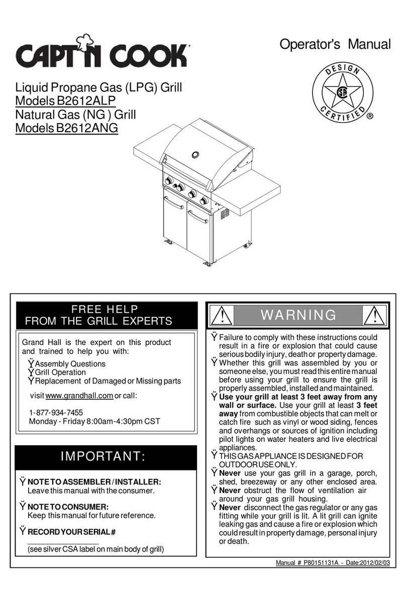
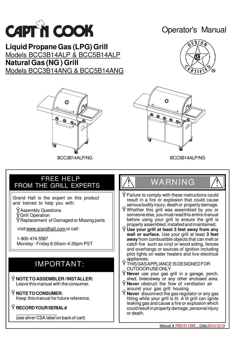
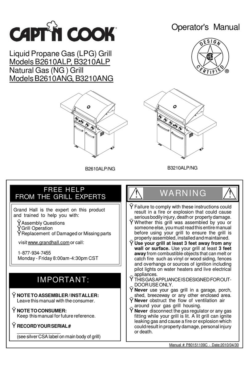
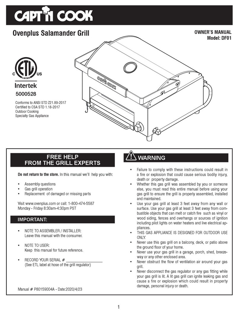
Capt'n Cook BCC5BO14ALP User manual

Manual#P80151144A-Date:2015/2/3
Failuretocomplywiththeseinstructionscould
resultinafireorexplosionthatcouldcause
seriousbodilyinjury,deathorpropertydamage.
Whetherthisgrill wasassembled byyouor
someoneelse,youmustreadthisentiremanual
beforeusing yourgrilltoensurethe grillis
properlyassembled,installedandmaintained.
Use yourgrill atleast3feetaway fromany
wall orsurface. Useyourgrill atleast 3feet
awayfromcombustibleobjectsthatcanmeltor
catchfiresuchasvinylorwood siding,fences
and overhangsorsourcesof ignition including
pilotlightson waterheatersand liveelectrical
appliances.
THISGASAPPLIANCEISDESIGNEDFOR
OUTDOORUSEONLY.
Never useyourgasgrillinagarage,porch,
shed,breezewayoranyotherenclosedarea.
Never obstructthe flowofventilation air
around yourgasgrill housing.
Never disconnectthe gasregulatororanygas
fitting while yourgrillislit. Alitgrill canignite
leakinggasandcauseafireorexplosionwhich
couldresultinpropertydamage,personalinjury
ordeath.
Ÿ
Ÿ
Ÿ
Ÿ
Ÿ
Ÿ
WARNING
! !
Ÿ
Grill Information Center:
Ÿ
Ÿ
NOTETOASSEMBLER/INSTALLER:
Leavethismanualwiththeconsumer.
NOTETOCONSUMER:
Keepthismanualforfuturereference.
RECORDYOURSERIAL#
__________________
(seesilverCSAlabelonbackofcart)
IMPORTANT:
Ÿ
FREEHELP
FROMTHEGRILLEXPERTS
Grand Hall isthe expertonthisproduct
andtrained tohelpyouwith:
visitwww.grandhall.comorcall:
1-800-474-5587
Monday-Friday8:00am-4:30pmPST
AssemblyQuestions
GrillOperation
ReplacementofDamagedorMissingparts
Ÿ
Ÿ
Ÿ
Operator'sManual
LiquidPropaneGas(LPG)Grill
MODELBCC5BO14ALP
NaturalGas(NG)Grill
MODELBCC5BO14ANG
5000528

Primary SafetyWarnings............................1-3
Pre-AssemblyInstructions................................3
PartDiagramsandLists............................4-7
AssemblyInstructions.................................8-11
Use&CareInstructions:
•GasSafetyand LeakTests..............12-14
•NaturalGasConnection............................15
•LightingInstructions..............................16-17
•Troubleshooting...........................................18
CleaningandMaintenance.......................19-20
CookingGuide..........................................A1-A6
FrequentlyAsked Questions..................A7-A8
Warranty...........................................Back Cover
TableofContents
2
Donotstoreorusegasolineorother
flammableliquidsorvaporsinthe
vicinityofthisoranyotherappli-
ances.
AnLPcylindernotconnectedfor
useshallnotbestoredinthevicinity
ofthisoranyotherappliance.
1.
2.
•LPGmodelsmustbeusedwithLiquidPropane
Gasandtheregulatorassemblysupplied.Natural
GasmodelsmustbeusedwithNaturalGasonly.
Anyattempttoconvertthe grillfromonefueltype
toanotherisextremelyhazardousandwillvoidthe
warranty.
Keepgas regulatorhose awayfromhotgrill sur-
faces and dripping grease.Avoidunnecessarytwist-
ing ofhose.Visuallyinspecthose priortoeach use
forcuts,cracks,excessivewearorotherdamage.
Ifthehose appearsdamageddo notuse thegas
grill.Call 1-800-474-5587 foracertifiedreplace-
menthose.
CaliforniaProposition65
Combustionbyproductsproduced when using this
productcontainchemicalsknowntotheStateofCali-
forniatocause cancer, birthdefects,orotherreproduc-
tiveharm.
Brass componentson thegrill,such as hose fittings,
propanecylindervalves (soldseparately)and burner
valvestems,containleadwhich isknowntotheState
ofCaliforniatocause cancer, birthdefects,orother
reproductive harm.
Neveruse charcoal orlighterfluidinthisgas Grill.
Failuretocomplywiththese instructionscouldresult
inagrease fireorexplosion thatcouldcause serious
bodilyinjury,deathorpropertydamage.
Beforeeachuseofyourgrill,inspecttheGreaseTray/
Receptacleand insideof theGrill Bowltobesurethere
isno excessivegrease and debrisbuildup.Cleanthe
Grease Tray/Receptacleand insideoftheGrill Bowl
frequentlytoeliminategrease/debrisbuild-up and to
preventgrease fires. Failuretocomplywiththese
instructionscouldresult inagreasefireand even a
subsequentexplosionthatcouldcauseseriousbodily
injury,deathorpropertydamage.
•
•
•
•
!
Thisappliance,when installed,mustbe electri-
callygrounded inaccordancewithlocalcodes
or,inthe absenceoflocalcodes,withthe
National Electrical Code,ANSI/NFPA 70, orthe
Canadian Electrical Code,CSA C22.1.
Keep anyelectricalsupplycordand the fuel
supplyhoseawayfromanyheated surfaces.
•
•
WARNING !
DANGER
!!
1.
2.
3.
4.
Ifyousmell gas:
Shutoff gas totheappliance.
Extinguishanyopenflame.
Openlid.
Ifodorcontinues,keepawayfrom
theappliance andimmediatelycall
yourgas supplieroryourfire
department.
WARNING
! !
WARNING
! !
Never coverorwraptheCooking Grids,bottom
oftheGrill Bowl,Grease Tray/Receptaclewith
aluminumfoil oranyothermaterialthatwill
absorbgrease.
! !
WARNING

Pre-AssemblyInstructionsForYourSafety
CAUTION
! !
Failuretocomplywiththeseinstructionsmay result
inahazardoussituationwhich,ifnotavoided,may
resultininjury.
Forsafeoperation ensuretheGas ValveAssembly
OrificeisinsidetheBurnerTubebeforeusing your
grill.(See figure). IftheOrificeisnotinsidethe
BurnerTube,lightingthe Burnermaycause
explosion and/orfireresulting inseriousbodily
injuryand/orpropertydamage.
METHOD 1:Bend astiff wireorwirecoathanger
intoasmall hook as shownand run thehook
through theBurnerTubeand insidetheBurner
severaltimes toremovedebris.
METHOD 2:Use abottlebrushwithaflexiblehandle
and run thebrushthrough theBurnerTubeand
insidetheBurnerseveraltimes toremoveany
debris.
METHOD 3:Use anairhose toforceairthrough
each BurnerTube.Theforcedairshouldpass
debrisorobstructionsthrough theBurnerand out
thePorts.
TOCLEANBURNERTUBE,
INSERTHOOK
HERE
9
3
1.
2.
3.
4. Refertothefigurebelowandperformone ofthese
3cleaningmethods:
CarefullylifteachBurnerupandaway fromtheGas
ValveOrifice.
CheckandcleanBurner/Venturi Tubesfor insectsand
insectnests.Acloggedtubecanlead toafirebeneath
the grill.
Spidersand small insectscanspinwebsand nest
inthegrill BurnerTubes during transitand ware-
housing which canleadtoagas flowobstruction
resulting inafireinand around theBurnerTubes.
Thistypeof"FLASHBACK FIRE"cancause serious
grill damageand createanunsafeoperating con-
dition fortheuser.
Toreduce thechance ofFLASHBACK FIRE
you mustcleantheBurner Tubes as follows
before initialuse. Alsodo thisatleastoncea
monthinsummerand fall orwheneverspidersare
activeinyourarea,and ifyourgrill has notbeen
usedforanextendedperiod oftime.
Remove theRcotter pinfromtherear ofeachBurner
usinganoseplier.
•
•
•
PRE-ASSEMBLY
Readandperformthefollowingpre-assemblyinstruc-
tions:
ToolsRequiredforAssembly:
protectiveworkgloves
protectiveeyewear
Youwillneedassistancefromanotherpersontohandle
thegrillandotherlarge,heavy parts.
Openlidofshippingcarton.Removetopsheetof
cardboardandpacking materials.Lay cardboardsheet
onflooranduseasaworksurfacetoprotectfloorand
grillpartsfromscratches.
Youmayslicethecartonfrontcornerswithautilityknife
tolayopenthecarton frontpanel.Thisallowsyou to
raise theLidand remove thecomponentspackedin-
side,makingiteasiertolift.
UsetheHardwareandPartDiagramstoensureall items
areincluded andfreeofdamage.
Donotthrowawaythebagsofhardwarethatarein-
cluded withboxedparts.These arerequiredforassem-
bly.
Donotassembleoroperatethe grillifitappearsdam-
aged.If therearedamagedormissingpartswhenyou
unpacktheshippingboxoryou havequestions during
the assemblyprocesscall 1-800-474-5587 M-F
8AM-4:30PMPST forassistance.
Orifice BurnerTube
nose plier
BurnerTube BurnerPort Foot
Grill Installation Codes
Theinstallation mustconformwithlocalcodes or, inthe
absenceoflocalcodes,witheithertheNationalFuel
Gas Code,ANSIZ223.1/NFPA 54,NaturalGas and
PropaneInstallation Code,CSA B149.1,orPropane
Storageand Handling Code,B149.2.
WARNING: Grease cangetveryhot. AlwayshandletheGrease
ReceptaclewithaflameretardantBBQmitt. Beforeremoving
theReceptacle,alwaysbesurethatthegrill has properly
cooled.BeawarethattheReceptacledoescontaingrease
andbeextremelycarefulwhenremoving the Receptacleto
preventspillage.Failuretofollowthese instructionscould
cause serious bodilyinjuryorpropertydamage.

Hardware Parts List for Model BCC5BO14ALP &BCC5BO14ANG
4
Hardware Diagramfor Model BCC5BO14ALP &BCC5BO14ANG
PhillipsHeadScrew
M6X30
Qty.2
Part#S112M0630A
PhillipsHeadScrewM6X15
Qty.18
Part#S112M0615A
SpringWasher
Qty.12
Part#S431M06091
PlainWasher
Qty.12
Part#S411M06161
PhillipsHeadScrew
M4X12
Qty.4
Part#S112M0412A
AA Battery
Qty.1
Screwdriver
Qty.1
(AA) (BB) (CC)
(DD) (EE)
PART# PARTDESCRIPTION QTY PURPOSEOFPART
P06013025B HardwarePack 1 For useinassemblyof BCC5BO14ALP/NG
S112M0615APhillipsHead ScrewM6x15 12
S411M06161 PlainWasher 12
S431M06091 SpringWasher 12
S112M0615APhillipsHead ScrewM6x15 6
S112M0630APhillipsHead ScrewM6x30 2
S112M0412APhillipsHead ScrewM4x12 4 InstallSideBurner and ControlKnob Seat
AA Battery 1
Screwdriver 1
InstallCasters
InstallSideShelfand SideBurner FrametoBowl
(FF)

PartsDiagramforModelsBCC5BO14ALP&BCC5BO14ANG
5

PartsList forModelBCC5BO14ALP&BCC5BO14ANG
6
KEY DESCRIPTION PART# QTY
1LidAssembly P0014754K4 1
2TemperatureGauge P00601601C 1
3TemperatureGauge Seat P00614047E 1
4 LidHandle P00205118M 1
5 LidHandleSpacer P06801039F 2
6WarmingRack P01507034H 1
7A GrillPlateW341 P01615060H 2
7B GrillPlateW186 P01615061H 1
8GrillBowl P0077115F4 1
9A Burner/Main P02003060F 5
9B BurnerBracket P022051684 1
GasValve/ManifoldAssembly(LPG) Y0060824 1
GasValve/ManifoldAssembly(NG) Y0060837 1
10B ManifoldBracket P03327122D 1
11 ElectricWiresSet/Electrode P02614064A 1
12A ProtectivePad P05518112K 2
12B ProtectivePad P05518113K 5
13 ElectricIgnitor, 6ports P02502435F 1
14 ControlPanel P0291444LS 1
15 ControlKnob Seat P034230144 8
16 ControlKnob P03401493V 7
17A GreaseTray P0270715RG 1
17B GreaseReceptacle P02701377A 1
18 SideShelf Connecting Bracket,Left P012020044 1
19 SideShelf Connecting Bracket,Right P012030054 1
20A SideShelf, Left P01125024B 1
20B Timer P05394001B 1
21 SideBurnerLid P0011560L4 1
22 SideBurnerFrame P011080184 1
23 SideBurnerBody P02302016K 1
24 SideBurnerHead P02001068A 1
25 SideBurnerCap P02013062D 1
26 SideBurnerPotSupport P00801002F 1
SideBurnerGasValveAssembly(LPG) Y0060827 1
SideBurnerGasValveAssembly(NG) Y0060831 1
27B SideBurnerElectrode withwire P02614065C 1
28 RegulatorwithHose(LPG) P03647002A 1
SideBurnerConnecting Hose(LPG) P03705106D 1
SideBurnerConnecting Hose(NG) P03705108D 1
30A Cart Assembly Y0050075 1
30B Cart Panel,Rear P07702139J 1
31 ThermocoupleforWarmerBurner P05305074A 1
32 Cooking Rack P01601029H 1
33 GreaseTray/Warmer P0271909QA 1
34 BaseTray/Warmer P05705009H 1
35 Burner/ Warmer P02003061A 1
36 Door /Warmer Y0410021 1
37 Door Handle/ Warmer P00205117M 1
38 TemperatureGauge forWarmer P00601601A 1
39 Door Magnet P05523058M 1
40 Door /Cart Y0410022 1
41 Door Handle/ Cart P00205117M 1
42 TankFasteningStrap P05314016V 1
43 ControlKnob forWarmer P03401523V 1
44 3"Caster withBrake P05112032A 2
45 3"Caster withoutBrake P05112033A 2
10A
27A
29

PartsList forModelBCC5BO14ALP&BCC5BO14ANG
7
ETLLabel
Important: UseonlyGrand Hall replacementparts.TheuseofanypartthatisnotaGrand Hall replacementpartcanbe
dangerousand will alsovoid yourproductwarranty.Keep thisOperator'sManualforconvenientreferralandforpart
replacement.
Fortherepairorreplacementpartsyouneed:
Call 1-800-474-5587 M-F8AM-4:30PMPST
Toobtain thecorrectreplacementpartsforyourgasgrill,pleaserefertothepartnumbersin thispartslist. The
following informationisrequiredtoensureyoureceivethecorrectparts:
1.Modeland SerialNumber(see ETLlabelongrill)
2.PartNumber
3.PartDescription
4.Quantityofpartsneeded
KEY DESCRIPTION PART# QTY
46 NGConnectingHose P03705109F 1
47 NGRegulator P03641007C 1
48 Hose,12FT.(NG)1/2"ID(soldseparately) P03704002A 1
49 Lighting Stick P05507145M 1
HardwarePack P06013025B 1
Operator'sManual P80151144A 1

8
AssemblyInstructionsforBCC5BO14ALP&BCC5BO14ANG
CAUTION :Eventhough itispossibleforoneperson toinstall thisgrill,itisbettertoobtainassistancefromanother
person whenhandling thelarge,heavy pieces.
InstallCasters
1
Install SideShelfandSide BurnerFrame
2
PlainWasher
Qty.12
Part#S411M06161
SpringWasher
Qty.12
Part#S431M06091
PhillipsHeadScrew
M6X15
Qty.12
Part#S112M0615A
(AA)
(BB)
(CC)
(CC)
PhillipsHeadScrew
M6X30
Qty.2
Part#S112M0630A
(DD)
PhillipsHeadScrew
M6X15
Qty.6
Part#S112M0615A
Openlidofshipping carton and removepacking materials.Layapieceofcardboardon theground.Withthe
helpofyourassistant, lift and laythegrill on thecardboardcarefullyas shown.
Install twoCasterswithbraketotheCart Seaton theleftsideofcart bottom.And install twoCasterswithout
braketotheCart Seaton therightsideofthecart bottomusing twelve(12)PlainWashers,Spring Washersand
Phillips HeadScrewsM6X15(three foreach Caster)andtightenthescrewssecurelyusingthescrewdriver
provided.
Withyourassistant, standthegrillup carefully.
Loosenthetwopre-installedscrewson bothsides ofRightBowlSidePanelhalfway.
Attach theSideBurnerFrametotheRightBowlSidePanelbymatching theslottedholes on theSide
BurnerFrameintothehalfwayscrewson theRightBowlSidePanel.Press theSideBurnerFrame
downwardsuntil itrestsinplace.Next, attach 3PhillipsHeadScrewsM6X15(See "CC"). Donottighten
thescrewsuntil themiddlescrewisattached.
Align theonemiddleholeon theedgeoftheSideBurnerFramewiththemiddleholeon theRightBowl
SidePanel.Insert the1PhillipsHeadScrewM6X30(See "DD")frominsideofthegrill bowland tighten
securely.
Tightenall thescrewssecurelyusing thescrewdriverprovided.
Repeatthesameprocedures fortheSideShelf.
CasterwithBrake
CartSeat
(pre-assembled)
SideShelf
SideBurnerFrame
Pre-installedscrew

9
3
(EE)
PhillipsHeadScrew
M4X12
Qty.4
Part#S112M0412A
Timer
ControlKnob
ControlKnobSeat
Insert SideBurnerGas Valvestemthrough theholeon thefrontoftheSideburnerFrame.Thenplace
theControlKnob Seatoverthegas valvestem,aligning theholes on theKnob Seat, SideBurnerFrame
and Gas ValveAssembly,tightensecurelyusing two(2)M4x12 PhillipsHeadScrews.
Bend thealuminumtubegently.SecuretheSideBurnerBase attheend ofaluminumtubeunderthe
SideBurnerBodyusing two(2)M4x12 PhillipsHeadScrewsas shownand tightensecurely.
Makesurethe Electrode goesthroughthe holeontheSide BurnerBody.
Install ControlKnob ontoGas ValvestemwithOFF position pointing up.
Install theTimer: RemovetwoscrewsfromTimer. Theninsert theTimerthrough theholeon thefront
oftheleft sideshelf. Placethecontrolknob seatovertheTimerstem,aligning theholes on them,tighten
securelyusing thesamescrewsprovidedas shown.Attach thecontrolknob ontotheTimerstem.
Install Side BurnerGas Valve Assembly,ControlKnob Seatand Timer
DoorHandle/Warmer
Door/Warmer
wingnut
DoorHandle/Cart
4Install DoorHandles and Grease Receptacle
ForCartDoorHandle:Removethe pre-assembled screwsandspacersfromthe doorhandle.
Reservethe screwsandspacersforthe nextstep.
Installthe doorhandletocartdoorusingthe reserved2screwsandspacersandtightenthe screws
securelyusingthescrewdriverprovided.
ForWarmerDoorHandle:Removethe pre-installedwingnuts,screwsandspacersfromthedooras
shown.(Note:Keep thescrewsandspacersforthedoorinstallationonly,takethewingnutsout.)
Installthe WarmerHandletothe Doorusingthereserved 2screwsandspacersandtighten securely.
Installthe GreaseReceptaclefromthe rearsideofgrillasshown
GreaseReceptacle
Viewfor
side burner
installation

10
6Install IgnitorBatteryand LP Gas Cylinder
Remove IgnitorCap fromControlPanel.
Place supplied AAbatteryintothe IgnitorSlotwithpositivepolefacingyou.
Installthe CapandSpringovertheAAbatteryandtighten securely.
InstallGasCylinderrefertopage 13formoreinformation.SecurecylinderwithFastenStrap.
(FF)
FastenStrap
Always keepLPGcylinders in upright
position during use,transport,and storage.
AA Battery
IgnitorCap
5Install NG Regulatorand 12 FootHose
Remove twopre-installed screwsfromNGRegulator.Keep themforthe nextstep.
Installthe NGRegulatorontotheRightCartSidePanelusingthe reserved2screwsandtighten
securely.
Connectthe swivelnutof12FootHosetoNGRegulatorinletasshown.
NG Regulator
InletFitting
SwivelNut
12 FootHose
PhillipsHeadScrew
3/16"x3/8"
Qty.2
Part#S112G03061
Alreadyinstalled
inNGRegulator
AA Battery
Qty.1

11
FinalGrill AssemblyStep
When you havefinished assemblingyourgrill,
besurethatallscrewsaretightenedforsafe
operationofyourgrill.
Beforeeachuseofthegrill,makesurethe
GreaseReceptacleisfullyseatedundertheGrill
Bowl.
CAUTION: Beforeeach use ofyourgrill, inspect
theGreaseTray/ReceptacleandinsideoftheGrill
Bowltobe surethereisno excessive grease and
debrisbuildup.CleantheGreaseTray/Receptacle
andinside oftheGrillBowlfrequentlytoeliminate
grease/debrisbuild-upandtopreventgreasefires.
SparkElectrode
Tip
Burner
AA Batterymaybeinstalledbackwards.
Electricwires maybe loose.Removethe AA
Batteryandinspectthe IgnitorJunctionBox
found behind the ControlPaneland recon-
nectanyloose wires.
-
-
Main/Sizzle/WarmerBurnerElectrode Check,
withthe assistance ofanotherperson,
performthisElectrode Check before
proceeding.
7
Besureall ControlKnobsaresetto"OFF"and
opentheGrill Lidand Door.
Haveyourassistantstand totherightofthe
grill and look towardthefrontofthegrill bowl.
Never putyourfaceinsidetheGrill Bowland
Warmer.
Press theIgnitorCap.You shouldheara
"clicking"sound.Yourassistantshouldsee a
bluesparkbetweentheBurnerand Spark
ElectrodeTip.IfasparkispresenttheElec-
trodeTipsareproperlypositioned.
Ifno spark,check thefollowing situation:
ThistestwillensurethattheSparkElectrode
Tipsareproperlypositionedso yourgrilllights
easily.
Side BurnerElectrode Check
8Push andturnSideBurnerControlKnobtoHI.
Lookforsparkbetween electrodetipandBurner.
If youdon'tseeasparkfromthe sideburner,
adjustthegap between theelectrodetipand
burnerportto3/16".
SparkGap3/16"
9Place the CookingGrids ontheledge
abovethe Burners.
Place the WarmingRackintothe slotson
the GrillBowlsSidePanels.
NOTE:InstallthesmallGrilloverthe
center(Sizzle)burner.TheotherGrillPlates
canbeinstalledoreithersideofthe
barbecue.
Place the SideBurnerHead onthe Side
BurnerSeat.
Place the SideBurnerCap Overthe Side
BurnerHead.
Place the SideBurnerPotSupportin
mountingholesonthesurfaceofSide
BurnerBody.
WarmingRack
CookingGrid
SideBurner
PotSupport
SideBurnerCap
SideBurnerHead
Install Cooking Components

12
USE AND CAREINSTRUCTIONS
CORRECTLPGASTANK USE
The LPGastankmustbe constructed andmarkedin
accordancewiththe Specifications forLP-GasCylinders
oftheU.S.DepartmentofTransportation(D.O.T.)orthe
NationalStandardofCanada,CAN/CSA-B339,Cylinders,
SpheresandTubesforTransportationofDangerous
Goods,and Commission;as applicable.
The LPGastankmusthave ashutoffvalve,terminating
inanLPGassupplytankvalveoutlet,thatiscompatible
withaType 1tankconnectiondevice.TheLPGastank
mustalsohave asafetyreliefdevicethathasadirect
connectionwiththe vaporspace ofthetank.
The tanksupplysystemmustbe arranged forvapor
withdrawal.
The LPGastankmusthave acollartoprotectthe tank
valve.
Neverconnectan unregulated LPgastanktoyourgas
grill. Thegasregulatorassemblysupplied withyourgas
grillisadjustedtohavean outletpressureof11"water
column(W.C.)forconnectiontoan LPgastank.Only
usethe regulatorandhoseassemblysupplied withyour
gasgrill. Replacementhoseandregulatorassemblies
mustbe thosespecifiedbyManufacturer.
Have yourLPGasdealercheckthereleasevalve after
everyfillingtoensureitremains freeofdefects.
Always keepLPGastankinuprightposition.
DonotsubjecttheLPGastanktoexcessive heat.
Neverstorean LPGastankindoors.Ifyoustoreyour
gasgrillinthegarage always disconnectthe LPGas
tankfirstandstoreit safelyoutside.
LPGastanksmustbestored outdoorsinawell-
ventilated areaandoutofthe reachofchildren.
Disconnected LPGastanks mustnotbestoredina
building,garageoranyotherenclosed area.
The regulatorandhose assemblycanbe seenby
openingthe cartdoor.They mustbe inspectedbefore
eachuseofthe grill. Ifthe hoseisdamaged inanyway,
it mustbereplacedpriortousingthe grillagain.
Anyattempttoconvertthe grillfromone fueltype to
anotherisextremelyhazardousandwillvoidthe
warranty.
Neverlightyourgas grillwiththelidclosed orbefore
checkingtoensuretheburnertubesarefullyseatedover
thegasvalve orifices.
Neverallowchildrentooperateyourgrill.Donotallow
children orpetstoplay nearyourgrill.Always supervise
children andpetsiftheyareinthe vicinityoftheunit.
!WARNING !
Keepfireextinguisherreadilyaccessible.Inthe
eventofaoil/grease fire,do notattempttoextinguish
withwater. Use typeBextinguisherorsmotherwith
dirt, sand orbaking soda.
Intheeventofrain,turnoff theburnersand gas
supply.Waitforthegrill tocool,and thenplacea
coveron it.
Use yourgrill on alevel,stablesurfaceinanarea
clearofcombustiblematerials.
LPGasgrillmodelsaredesignedforusewithastandard
20lb.LiquidPropane Gas(LPGas)tank(soldsepa-
rately). Never connectyourgasgrilltoan LPGastank
thatexceedsthiscapacity.Atankofapproximately12
inchesindiameterby18-1/2incheshighisthemaximum
sizeLPGastanktouse. Youmustusean "OPD"gas
tankwhichhasalistedOverfill PreventionDevice. This
safetyfeaturepreventstankfrombeingoverfilled which
cancauseamalfunctionofthe LPGastank. Donotleavegrill unattendedwheninuse.
Donotmovetheappliancewheninuse.
Allowthegrill tocoolbeforemoving orstoring.
Donotuse yourgrill as aheater.
•
•
•
•
Use yourgrill atleast3feetawayfromanywall or
surface.
Use yourgrill 3feetawayfromanycombustible
objectsthatcanmeltorcatch firesuch as vinylor
wood siding,fences,overhangs(See DiagramBe-
low), oranyothersources ofignition;including pilot
lightsandliveelectricalappliances.
Donotuse yourgrill underanyoverheadcombus-
tibleconstruction.
Neveruse yourgas grill inagarage,porch,shed,
breezeway,oranyotherenclosedarea.
Neveruse yourgas grill on abalcony,deck,orpatio
abovetheground floorofyourhome.
Inwindyconditions,alwaysposition thefrontofthe
grill tofaceoncoming wind toreduceheatand
smokeblowing inyourface,and topreventpotential
hazardstoyourselfand thegrill.
•
!
DonotstoreaspareLP-Gastankunderornearthis
appliance.
Neverfillthetankbeyond80percentfull; and
Ifthe information in"(a)"and"(b)"isnotfollowed
exactly,afirecausingdeathorseriousinjurymay
occur.
A.
B.
C.
WARNING !
Useofalcohol,prescriptionornon-prescriptiondrugs
canimpairyourabilitytoproperlyassembleandsafely
operateyourgrill.
Never use charcoalorlighterfluidinthisgrill.
Thisgrill isnotintendedtobeinstalledinoron
recreationalvehicles and/orboats.
Thegrill isnotintendedforcommercialuse.
•
WIND
DIRECTION
3ft. 3ft.

13
USE AND CAREINSTRUCTIONS
BrushsoapysolutionontoLPGastankinthear-
easindicatedbythearrows.Seediagram.
Ifgrowingbubbles appeardo notuseormovethe
LPGastank.Callan LPGasSupplieroryourFire
Department.
NOTEaboutLPGas TankExchangePrograms
Manyretailersthatsell grillsofferyou theoption of
replacing your emptyLPGas tank through anexchange
service.Useonlythosereputableexchangecompa-
nies thatinspect, precision fill,testandcertifytheir
tanks.Exchangeyourtank onlyforanOPD safetyfea-
ture-equipped tankas described inthe LPGastank
sectionofthisguide.
How toLeak TestyourLPGas Tank
Use acleanpaintbrushand a50/50 mildsoapand
water solution.
Foryoursafety:
Leaktestnewand exchangedLPGas tanksBEFORE
connecting onetoyourgrill.
Alwayskeepnewand exchangedLPGas tanksinanup-
right position during use, transitor storage.
All leaktestsmustberepeatedeach timeyourLP
Gastank isexchangedorrefilled.
Whencheckingforgas leaksdonotsmoke.
Donotusean openflametocheckforgas leaks.
Yourgrill mustbe leaktestedoutdoorsinawell-ven-
tilatedarea,awayfromignitionsourcessuchasgas
firedorelectricalappliances.During the leak test, keep
yourgrillaway fromopen flames orsparks.
Donotusehouseholdcleaningagents.Damage to
gas assemblycomponentscanresult.
Ÿ
Ÿ
Ÿ
Ifgrowingbubbles appeardo notuseormovethe
LPGastank.ContactanLPGasSupplieroryourfire
department!
WARNING
!!
LPGas Modelonly:
Secure a20lb LPGas TanktoGas Grill
TurnyourLPGas Tank Valveclockwise tothe
closedorOFF position.
Openthecart doorand placetheLPGas Tank
intotherightsideofthebottompanelas shown.
BesurethatthebottomoftheTank fullyrestson
thebottompanel.
Thetank valveshouldbefacing theopening on
thecart rightsidepanel.
ConnecttheRegulatorwithHose tothegas
tank.(Refertopage14)
Securethegas tank withthetank fastening
strapas shown.
FastenStrap

14
WARNING
!
LPGasModelonly:
ConnectRegulatorwithHosetoyourLPGasTank
TurnallControlKnobstotheOFFposition.
Inspectthevalveconnectionport and regulator
assemblyfordamage ordebris.Remove anyde-
bris.Neverusedamagedequipment.
Connectthe regulatorassemblytothe tankvalve
andHANDTIGHTENnutclockwisetoafullstop.DO
NOTuseawrenchtotightenbecauseit could
damagetheQuickCouplingNutandresultinagas
leak/firehazard.
Openthetank valve1/4to1/2ofafull turn
(counterclockwise)and use asoapywatersolution
tocheck all connectionsforleaksbeforeattempt-
ing tolightyourgrill.See "Check All Connections
forLPGas Leaks."If aleakisfound,turnthe tank
valveoffanddonotuseyourgrilluntiltheleakis
repaired.
USE AND CAREINSTRUCTIONS
1.
WARNING
! !
DonotstorespareLPcylinderwithin
10 feet(3m)ofthisappliance.
Donotstoreoruse gasolineorother
flammableliquidsandvaporswithin25
feet(8m)ofthisappliance.
Whencookingwithoil/grease,do not
allowtheoil/grease togethotter350°F
(177°C).
Donotleaveoil/grease unattended.4.
2.
3.
Checkall connectionsforLPGasLeaks
Never testforleakswithan open flame.Priortofirst
use,atthe beginningofeachseason,oreverytime
yourLPGastankischanged,youmustcheckforgas
leaks.Followthesethreesteps:
Makeasoapsolution bymixing onepart liquid
detergentand onepart water.
Turntheall ControlKnobstothefull OFF position,
thenturnthegas ON atsource.
Applythesoapsolutiontoall gas connections
indicatedbythe arrows.(See diagram). Ifbubbles
appearinthesoapsolution theconnectionsare
notproperlysealed.Check each fitting and tighten
orrepairas necessary.
Type1connectionperANSI
STDZ21.58b-2012/CSA
STD1.6b-2012
Quick
Coupling Nut
CAUTION: Whentheapplianceisnotinuse thegas must
beturnedoff atthetank.Placedustcapon cylindervalve
outletwheneverthecylinderisnotinuse.Onlyinstall the
typeofdustcapon thecylindervalveoutletthatisprovided
withthecylindervalve.Othertypes ofcapsorplugsmay
resultinleakageofpropane.
Ifyou haveagasleakthatcannotbe repaired,
turnoff the gasatthe sourceand disconnectthe
fuelline fromyourgrill. Call1-800-474-5587 oryour
gassupplierforrepairassistance.
!
Disconnecting ALiquid PropaneGas (LPG)
TankFromYourGrill
MakesuretheBurnerValves and LPGas tank valve
areoff. (Turnclockwise toclose.)
Detach thehose and regulatorassemblyfromthe
LPGas tank valvebyturning theQuick Coupling
Nutcounterclockwise.Donotuse awrench orany
toolswhenturning theQuick Coupling Nut.
WARNING !
Failure toreadand follow theUse and Care
Instructionscould resultin afire orexplosion
thatcouldcauseseriousbodilyinjury,death,or
propertydamage.
!
Regulator
withHose(LPG)
LPGasTank

15
NaturalGas Connection
NaturalGas Modelonly:
Connecting NaturalGas ToYourGrill
Check allconnectionsforNaturalGasLeaks
Never testforleakswithan openflame.Priortofirstuse
andatthebeginningofeachseason,youmustcheck
forgasleaks.Followthesethreesteps:
Makeasoapsolution bymixing onepart liquid
detergentand onepart water.
TurnthegrillControlKnobstotheirfull OFF
positions.Next, turnthegas ON atthesource.
Applythesoapsolutiontoall gas connections
indicatedbythearrows.See Fig.3.Ifbubbles
appearinthesoapsolution theconnectionsare
notproperlysealed.Check each fitting and tighten
orrepairas necessary.
Fig.2
GasSupply
InsideWall
OutsideWall
MaleFitting
ToGrill
Locking
ShutOff
ShutOff
Quick
Disconnect
Yournaturalgas grill isdesignedforuse with
naturalgas (NG)only.Thegas pressureRegu-
latorsuppliedwiththisappliance must bein-
stalledand usedon yourgrill.Theunitand
Regulatoraresettooperatewithanoutlet
pressureof4"W.C.
Install aShutoff Valveatthegas supplysource
outdoorsatapointafterthegaspipeexitsthe
outsidewall and beforethequick-disconnecthose.
Orinstall itatthepointbeforethegas linepiping
enterstheground.See Fig.2.
Pipesealing compound orpipethreadtaperesis-
tant totheaction of naturalgas mustbeusedon all
malepipethreadconnections.
Disconnect yourgas grill fromfuelsourcewhenthe
gas supplyisbeing testedathigh pressures.This
gas grill anditsindividualshutoff valvemustbe
disconnectedfromthe gassupplypipe system
during anypressuretestingofthatsystemat
pressureinexcess of1/2psi(3.5kpa).
Turnoff yourgas grill whenthegas supplyisbeing
testedatlowpressures.Thegrill mustbeisolated
fromthe gassupplypipesystembyclosingits
individualmanualshutoffvalveduring anypres-
suretesting ofthegassupplypipesystemat
pressures equaltoorless than1/2psi(3.5kpa).
NaturalGasSafetyInstructions
ConnecttheSwivelnutofthe 12'NaturalGas
Hose totheVerticalfittingofNG Regulatoras
shownin Fig.1.Connecttheotherhose end
(maleplug)tothegas supplylinefromyour
home.Readand followthe"NaturalGas Safety
Instructions"below.
Fig.3
Fig.1
Hose,12 ft./ NG
Swivelnut
Verticalfitting
Please contactcertifiedgas technicianforgas linepiping
installation.
GasLinePiping:
NGRegulator Hose,12 ft./ NG

USE AND CAREINSTRUCTIONS
16
5.
8.
7.
9.
6.
SetControlKnobstoOFFandopentheLPGas tankvalve
SLOWLY1/4~1/2ofafull turn.ForNaturalGasopenthe
ShutOff Valveatsource.
Pushand turnRightMainBurnerControlKnob to IGN.
Immediatelypress theElectricIgnitorButton forup to
3-4secondstolighttheburner.
Ifignition does notoccurin5seconds,turntheBurner
Control(s)off, wait5minutes,andrepeatthelighting
procedure.Ifignition still does notoccur, turntheburner
control(s) and gas sourceOFF. Wait5minutes forgas to
clearand thenconductaleaktestofALL gas connections
andgassourcesasexplainedintheUseandCare
section ofthismanual.Ifno leaksaredetected,wait5
minutesforanygastoclearandrepeatthe lighting
procedure.
AfteroneBurnerislit, turnthetank valveSLOWLYone
more1/4ofaturn.
Turneach otherburnerknob toHItolightindividually.
Note: Whenlighting all mainburners,start withtheburner
furthestfromfuelsource location,thenlightremaining
burnersinsequencemovingtowardfuelsource.
Failuretoreplaceafaultyhose,securegas supply
connectionsortoopentheLidbeforeproceeding to
theLighting Procedures couldresultinafireor
explosionthatcouldcause seriousbodilyinjury,
death,orpropertydamage.
WARNING
!!
Main Burner Lighting Instruction
1.Beforeeach use,check all hoses forcracks, nicks,cuts,
burnsorabrasions.Ifahose isdamagedinanyway,do
notuse yourgrillbeforereplacingthe hosewithan
authorizedpart fromthePartsList. Alsomakesureall
gas supplyconnectionsaresecurelytightened.
Familiarize yourselfwithall Safetyand Use and Care
instructionsinthismanual. Donotsmokewhile
lighting yourgrill orwhenchecking thegas supply
connections.
BesurethattheLPGas tank isfilled,and lock
Casterstopreventmovementduring grill operation.
OpentheGrill Lid.
4.
3.
2.
SideBurner Lighting Instruction
Followsteps1through 5oftheGrillLighting
Instructions.
Pushand turnControlKnobto IGN/HIGH.
The built-insparkignitorwilllighttheburnerauto-
matically.
You mayhavetopushand turnthecontrol knob up to
3or4times tolight.
Ifignition does notoccurin5seconds,turntheBurner
Control(s)off, wait5minutes,and repeatthelighting
procedure.Ifignition still does notoccur, turnthe
burnercontrol(s)and gas sourceOFF.Wait5minutes
forgastoclearand thenconductaleaktestofALL gas
connectionsandgassources asexplainedinthe
Use and Caresection ofthismanual.Ifno leaksare
detected,wait5minutes foranygas toclearand
repeatthelighting procedure.
AfterBurnerislit, turnthetank valveSLOWLYone
more1/4ofaturn.
1.
5.
3.
4.
2.
6.
OpenLPGas tank
OFF
OFF
OFF
LOW
IGN/SIZZLE HIGH
MainBurner
(Sizzle)
OFF
SIZZLE
Main Burner
(Sizzle)
Main Burner Main Burner
WarmerBurner

ManuallyLighting YourGrill By Paper Match
To lightyour gas grill/warmer bymatch,insert amatch into
theLighting Stick and followsteps1through 5ofthegrill
LightingInstructions.Then,lightthematch and place
Lighting Stick through theCooking Gridson thegrill or the
holeunderthebase trayinthewarmer(See Diagrams
Below)tolightthemain/sizzle/warmerburners.Turnthe
correlatedControlKnob totheIGN setting torelease gas.
TheBurnershouldlightimmediately.
Warmer Burner Lighting Instruction
USE AND CAREINSTRUCTIONS
OpentheWarmerdoor.
Setburnercontrolknob to"OFF"and openthegas
cylindervalve.
Pushand turnthewarmerburnerknob inacounter
clockwise direction tothe"HI"position and holditin.
Immediatelypress theElectricIgnition Button forup to
15 secondstolighttheburner.
Iftheburnerdoes notlight, turntheburnercontrolknob
to"OFF"position,wait5minutes forgas toclear, then
retry.
Oncetheburnerisignited,continuetoholdintheknob
forabout10 secondsfortheflamefailureprotection
devicetoactivate.
NOTE:Theburnerneedstobefullylitbeforereleasing
theknob.
Adjustburnercontrolknobtoyourdesired cooking
temperature.
Ifignition cannotbe achieved.Referto"TROUBLE-
SHOOTING"on page18.
1.
MechanicalTimer Instruction
NOTE:The modelfeatures amechanical60min
timer.
Step1:Tousethe timer,turnthe controlknob
clockwisetofull setting first.
Step2:Slowlyturnthe timerbackwardstothe
position ofthe timerequired.
The timerwill ring oncethe pre-setindicated
timeisreached,howeverthe warmerwill remain
on.
NOTE: Ifyou don't turnthecontrol knob
clockwise tofull setting, thetimer will ring
forashorter period thannormal.
2.
3.
4.
5.
6.
7.
8.
17
Match
Lighting Stick
OFF

USE AND CAREINSTRUCTIONS
18
Never leanoverthegrill cooking area whilelighting
yourgas grill.Keepyourfaceand bodyasafedistance
(atleast18 inches)fromthefrontofgrill whenlighting
yourgrill bymatch.
WARNING
!!
Ifignition does notoccurin5seconds,turntheControl
Knob(s)and gas sourceOFF and conductaleaktest
as explainedintheUse and Caresection ofthisguide.
Ifno leaksaredetected,wait5minutes foranygas
toclearand repeatthelighting procedure.
WARNING
!!
WARNING !!
ShouldaFLASHBACKfireoccurinoraroundthe Burner
Tubes,followthe instructions below.Failuretocomply
withtheseinstructions couldresultinafireorexplosion
thatcouldcauseserious bodilyinjury,death,orproperty
damage.
Shutoff gas supplytothegas grill.
TurntheControlKnobstoOFF position.
OpentheGrill Lid.
PutoutanyflamewithaClass Bfire
extinguisher.
Oncethegrillhas cooleddown,cleanthe
BurnerTubes and Burnersaccording tothe
cleaninginstructionsinthisUseand Care
Guide.
Ÿ
Ÿ
Ÿ
Ÿ
Ÿ
Troubleshooting
Ifthegrill fail tolight:
MisalignmentofBurnerTubesoverOrifices
Correction: RepositionBurnerTubesoverOrifices.
Obstruction ingas line
Correction: Removefuelline fromgrill.Donot smoke!Open
gassupplyforonesecondtoclear anyobstructionfromfuel
line.Closeoffgassupplyatsource andreconnectfuelline
togrill.
PluggedOrifice
Correction: RemoveBurnersfromgrill byremoving the
cotterpinfromtherearofeach Burnerusing anose plier.
Carefullylift each Burnerup andaway fromgas valve
Orifice.RemovetheOrifices and gentlyclearanyobstruc-
tion withafinewire.Thenreinstall all Orifices,Burnersand
cookingcomponents.
Ifanobstruction issuspectedinGas Valves orManifold,
call theGrill Information Center1-800-474-5587
Monday-Friday8:00am-4:30pmPST.
Obstruction inBurnerTubes
Correction: FollowtheBurnerTubecleaning procedureon
page 20 ofthisOperator'sManual.
MisalignmentofIgnitoron Burner
Correction: CheckforproperpositionoftheElectrodeTip
asshownin steps7on page11. Thegapbetween the
SparkElectrode TipandBurnershouldbeapproximately
3/16"wide.Adjustifnecessary.Withthegassupply
closed,turnanyBurnerControlKnobtoHI, presselectric
Ignitor and watchfor thepresenceof asparkat theend of
theElectrode
DisconnectedElectricWires
Correction: InspecttheIgnitorJunctionBoxfoundbehindthe
ControlPanel. ConnectlooseElectricwirestoJunctionBox
andtrytolightthe grill.
WeakAAbattery
Correction: RemovetheIgnitorCapand replacethebat-
tery.
Ifthegrill still does notlightyou mayneedtopurge
airfromthegas lineorresettheregulatorexcess gas
flowdevice. Note: Thisprocedureshouldbedoneevery
timeanewLPGas tank isconnectedtoyourgrill.
Turngas offatsourceandturnControlKnobstoOFF.Wait
atleast5minutes forgastoclear,thenretry.
Ifyourgrillstillfailstolight, checkgas supplyand
connections.
Repeatlighting procedure.Ifyourgrill stillfailstooper-
ate,turnthegas off atsource,turntheControl Knobsto
OFF,thencheckthefollowing:
1.
2.
3.
Topurgeairfromyourgas lineand/orreset
theregulatorexcess gas flow device:
TurnControlKnobstotheOFF position.
Turnoff thegas atthetank valve.ForNatural
Gas,close shutoff valve.
DisconnectregulatorfromLPGas tank.
ForNaturalGas,disconnectregulatorfrom
12 ft. NaturalGas Hose.
Letunitstand 5minutes toallowairtopurge.
ReconnectregulatortotheLPGas tank.
ForNaturalGas,reconnectregulatorto
12 ft. NaturalGas Hose.
Turntank valveon SLOWLY1/4ofafull turn.
ForNaturalGas openShutOff valve.
OpentheGrill Lid.
PushandturntheRightMainBurnerControlKnob
toIGN/HIGH.
Press ElectricIgnitorfor3-4secondstolight
theburners.

Cleaning ExteriorStainless SteelSurfaces:
Routinecareand maintenanceisrequiredtopreserve
theappearanceandcorrosionresistanceofstainless
steel.The factisstainlesssteelcancorrode,rustand
discolorundercertainconditions.Rustiscaused when
regularsteelparticles intheatmospherebecomeat-
tached tothestainlesssteelsurface.Steelparticlescan
also becomeattachedtoyourgrillifyouusesteelwool
orstiff wirebrushestocleanthegrillinstead ofnon-
abrasive cloth,sponge ornyloncleaningtools.Incoastal
areas rustpitscandevelop onstainlesssurfaces that
cannotbe fullyremoved.Bleachandotherchlorinebased
solutions used forhouseholdand poolcleaningcan
also causecorrosion tostainless steel.Weathering,
extremeheat,smoke fromcookingand machineoils
usedinthe manufacturing process ofstainlesssteel
cancause stainlesssteeltoturntanincolor.Although
therearemanyfactorswhich canaffectthesurfaceap-
pearanceofstainlesssteel,theydonotaffectthe integ-
rityofthe steelortheperformanceofthe grill.
Tohelpmaintainthefinishofstainlesssteelfollowthese
cleaningprocedures forthebestresults:
Aftereveryuse(afteryourgrillhas cooleddown),wipe
stainlesssurfaces withasoft,soapyclothorsponge
thenrinsewithwater.Besuretoremoveallfoodpar-
ticles,saucesormarinadesfromstainlesssteelbecause
thesecan be highlyacidicanddamagingtostainless
surfaces.
Neveruse abrasivecleaners,scrubbersorstiffwire
brushesofanytype onyourgrill.
UseaheatresistantStainlessSteelCleanerand rubor
wipeinthe directionofthe stainlesssteelgrainorpolish
lines.Donotpolishagainstthe grain.
1.
3.
2.
WARNING
! !
Failuretocomplywiththeseinstructions could
resultinafireorexplosion thatcouldcause
seriousbodilyinjury,deathorpropertydamage.
Keepgrill area clearand free fromcombustible
materials,gasolineandotherflammablevaporsand
liquids.
Donotobstructtheflowofairforcombustion and
ventilation.
Keeptheventilation openingsofthetank enclosure
cabinet free and clear of debris.
Visuallycheckburnerflames occasionallytoensure
proper flamepatternas shownbelow.
•
•
•
•
MAGNIFIEDVIEW OFGRILL MAINBURNERAND SIZZLE
BURNERFLAMETHROUGHOPENLID. FORWARMER
BURNER,THROUGHOPENDOOR.
19
GRILLCLEANINGAND MAINTENANCE
Proper careand maintenancewill keepyour grill intop operating
conditionandprolong itslife.Followthesecleaningprocedures on
atimelybasisand yourgrill will staycleanand operatewith
minimumeffort.
CAUTION: Besureyour grill isOFF and cool beforecleaning.
Beforeinitialuse,and periodicallythereafter, washyour
Cooking Gridsinamildsoapand warmwatersolution.
You canuse awashclothorvegetablebrushtocleanyour
Cooking Grids.
To reducethechanceof fire,theGrease Tray/Receptacle
shouldbevisuallyinspectedbeforeeach grill use.
Removeanygrease and washGrease Tray/Receptacle
withamildsoapand warmwatersolution.
Grease canbuildup on theinsideoftheGrill lidover time.
Thisgrease candripontoyourdeck orpatiowhenthelid
isopened.VisuallyinspecttheinsideoftheGrill Lid
beforeeach grill use.Removeanygrease and washwith
amildsoapand warmwatersolution.
CleaningtheCookingGrids
Cleaning theGrease Tray/Receptacle
Cleaning theInsideoftheGrill Lid
10.
1.
4.
5.
6.
7.
8.
9.
Burning-off excess food aftereverycookoutwill keepit
readyforinstantuse.However, atleastevery3months
you mustgivetheentiregrill athorough cleaning to
minimize yourriskofgrease fireand keepthegrill intop
shape.Followthese steps:
Turnall ControlKnobstothefull OFF position.
TurntheLPgas tank valvetothefull OFF position.
Disconnecttheregulatorfromthegas tank.Inspect the
hose withregulatorassemblyforcracking,cutsorany
otherdamage,and replaceas neccessary.Refertothe
PartsListinthisUse and CareGuide.
Removeand cleantheCooking Grids,Warming Rack
and Grill Burners.
Covereach Gas ValveOrificewithaluminumfoil.
Brushtheinsideand bottomof thegrill withafiberpador
nylon brushand washwithamildsoapand warmwater
solution.Rinse thoroughlyand letdry.
Removealuminumfoil fromOrifices and check each
Orificeforobstruction.
Check each SparkElectrode,adjusting as needed.The
space betweenthe SparkElectrode TipandBurner
shouldbeapproximately3/16".
ReplaceCookingGridsandWarming Rack.
Reconnectthegas sourceand observetheBurnerflame
forcorrectoperation.
RoutineCleaning ofTheGrill Interior
3.
2.
WARNING
! !
Donotleavethegrillunattendedduringburnoff.Empty
andcleanthegrease receptaclebeforedoing burn-
off.

ToreducethechanceofFLASHBACKFIREyoumustclean
theBurnerTubesas followsatleastonceamonthinsummer
andfallorwheneverspidersareactiveinyourarea,andifyour
grill has notbeenusedfor anextendedperiod oftime.
Regardless ofwhich Burnercleaning procedureyou
use,werecommend thatyou alsocompletethefollow-
ing cleaning regimenstohelpprolong Burnerlife.
Forsafeoperation,makesuretheOrifices are
insidetheBurnerTubes beforeusing yourgrill.
See figure.IftheOrificeisnotinsidetheBurner
Tube,lighting theBurnermaycause explosion and/
orfireresultinginseriousbodliyinjuryand/or
propertydamage.
1.
2.
3.
4.
5.
6.
7.
8.Referto Figure1 and performoneofthese three
cleaning methods:
20
Turnall BurnerValves tothefull OFF position.
TurntheLPGas tank valvetothefull OFF position.
ForNaturalGas,shutoff NaturalGas valve.
Removethecotterpinsfromtherearofeach Burner
using anose plier.
Removethecooking grids,and warming rack from
yourgrill.
Carefullylift each Burnerup and awayfromtheGas
ValveOrifice.
Check and cleanburner/venturitubes forinsectsand
insect nests.Acloggedtubecanleadtoafirebeneath
thegrill.
Detach theLPGas regulatorassemblyfromLPGas
Tank.
CLEANINGTHEBURNERTUBES AND BURNERPORTS
2.2.
WARNING
! !
TubeBurner
Aftereach use ofthemaingrill orsizzle cooking zone,it
isnecessarytoburnoff food particles and drippings
which canclog Burnerportsand reduceBurnerperfor-
mance.Ignitethe mainburners,lowertheLid,and
operategrill on HIsetting for10 to15 minutes.
Use anylon brush,blowerorvacuumtoremoveaccu-
mulatedashfromtheoutersurfaceofeach Burner.
CloggedtubestyleBurnerportscanbecleanedwitha
stiff wire,such as anopenpaperclip.
Inspecteach Burnerfordamage(cracksorholes)and if
such damageisfound,orderand install anewBurner.
Afterinstallation,check toensurethattheGas Valve
Orifices arecorrectlyplacedinsidetheendsof theBurner
Tubes.Alsocheck theposition ofyourSparkElectrode.
Figure 1
TOCLEAN BURNER
TUBE,INSERTHOOK
ASINDICATEDBYTHE
ARROW
METHOD 1:Bend astiff wireorwirecoathanger
intoasmall hook as shownand run thehook
through theBurnerTubeand insidetheBurner
severaltimes toremovedebris.
METHOD 2:Use abottlebrushwithaflexible
handleand run thebrush through theBurner Tube
and insidetheBurnerseveraltimes toremoveany
debris.
METHOD 3:Use anairhose toforceairthrough
each BurnerTube.Theforcedairshouldpass
debrisorobstructionsthrough theBurnerand out
thePorts.
9BurnerTube BurnerPort Foot
Orifice BurnerTube
This manual suits for next models
2
Table of contents
Other Capt'n Cook Grill manuals