Capt'n Cook B2612ALP User manual

Manual#P80151131A-Date:2012/02/03
Failuretocomplywiththeseinstructionscould
resultinafireorexplosionthatcouldcause
seriousbodilyinjury,deathorpropertydamage.
Whetherthisgrill wasassembled byyouor
someoneelse,youmustreadthisentiremanual
beforeusing yourgrilltoensurethe grillis
properlyassembled,installedandmaintained.
Use yourgrill atleast3feetaway fromany
wall orsurface. Useyourgrill atleast 3feet
awayfromcombustibleobjectsthatcanmeltor
catchfiresuchasvinylorwood siding,fences
and overhangsorsourcesof ignition including
pilotlightson waterheatersand liveelectrical
appliances.
THISGASAPPLIANCEISDESIGNEDFOR
OUTDOORUSEONLY.
Never useyourgasgrillinagarage,porch,
shed,breezewayoranyotherenclosedarea.
Never obstructthe flowofventilation air
around yourgasgrill housing.
Never disconnectthe gasregulatororanygas
fitting while yourgrillislit. Alitgrill canignite
leakinggasandcauseafireorexplosionwhich
couldresultinpropertydamage,personalinjury
ordeath.
Ÿ
Ÿ
Ÿ
Ÿ
Ÿ
Ÿ
WARNING
! !
Ÿ
Grill Information Center:
Ÿ
Ÿ
NOTETOASSEMBLER/INSTALLER:
Leavethismanualwiththeconsumer.
NOTETOCONSUMER:
Keepthismanualforfuturereference.
RECORDYOURSERIAL#
__________________
(seesilverCSAlabelonmainbodyofgrill)
IMPORTANT:
Ÿ
Operator'sManual
FREEHELP
FROMTHEGRILLEXPERTS
Grand Hall isthe expertonthisproduct
andtrained tohelpyouwith:
visitwww.grandhall.comorcall:
1-877-934-7455
Monday-Friday8:00am-4:30pmCST
AssemblyQuestions
GrillOperation
ReplacementofDamagedorMissingparts
Ÿ
Ÿ
Ÿ
LiquidPropaneGas(LPG)Grill
ModelsB2612ALP
NaturalGas(NG)Grill
ModelsB2612ANG

TableofContents
Primary SafetyWarnings............................1-3
Pre-AssemblyInstructions................................3
PartDiagramsandLists............................4-8
AssemblyInstructions.................................9-15
Use&CareInstructions:
•GasSafetyand LeakTests..............16-18
• NaturalGasConnection............................19
•LightingInstructions...................................20
•Troubleshooting...........................................21
CleaningandMaintenance.......................22-23
CookingGuide..........................................A1-A4
FrequentlyAsked Questions..................A5-A6
RepairProtectionAgreements......Back Cover
2
Donotstoreorusegasolineorother
flammableliquidsorvaporsinthe
vicinityofthisoranyotherappli-
ances.
AnLPcylindernotconnectedfor
useshallnotbestoredinthevicinity
ofthisoranyotherappliance.
1.
2.
•LPGmodelsmustbeusedwithLiquidPropane
Gasandtheregulatorassemblysupplied.Natural
GasmodelsmustbeusedwithNaturalGasonly.
Anyattempttoconvertthe grillfromonefueltype
toanotherisextremelyhazardousandwillvoidthe
warranty.
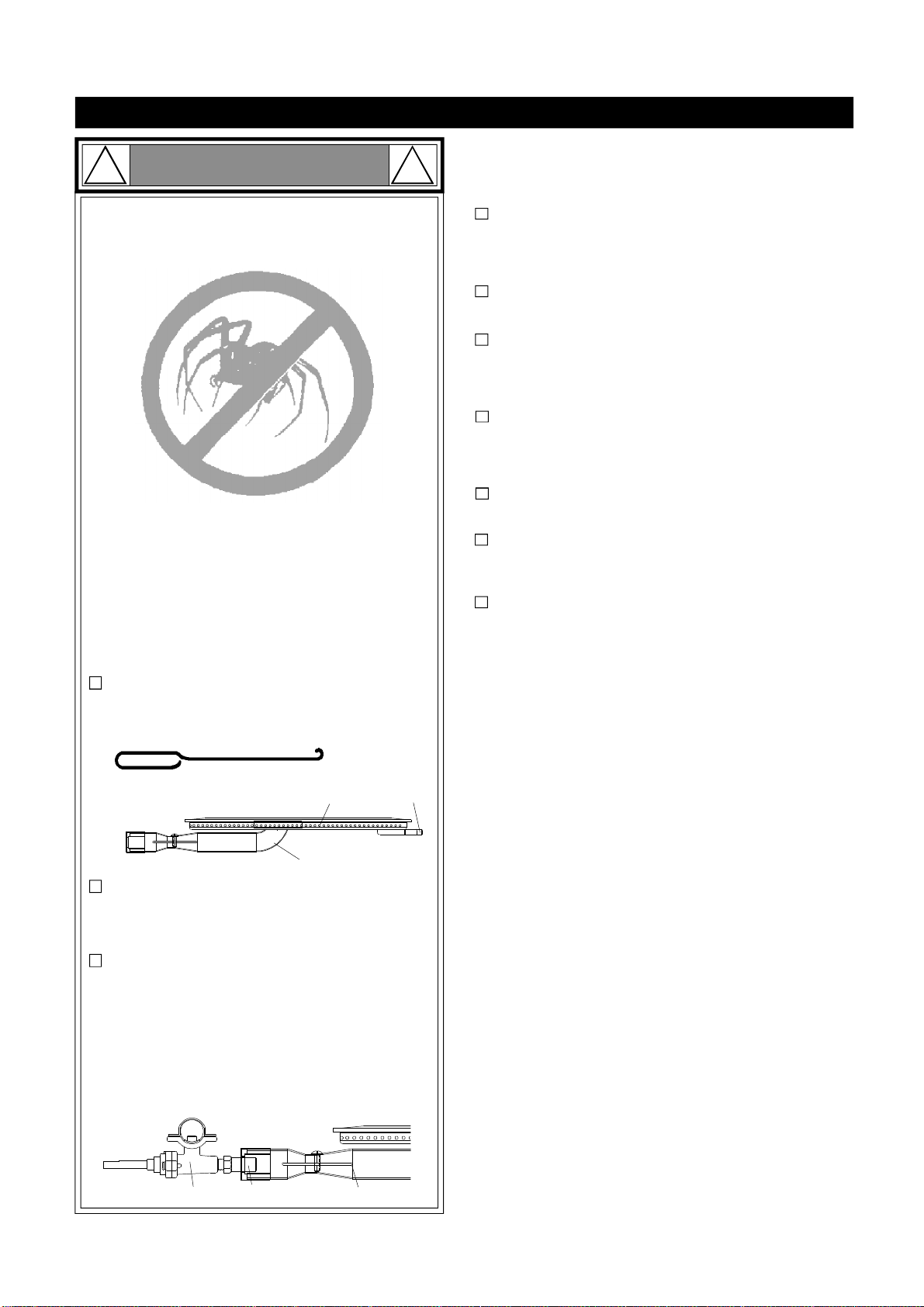
Keep gasregulatorhoseawayfromhotgrillsurfaces
anddrippinggrease.Avoidunnecessarytwistingof
hose.Visuallyinspecthosepriortoeachuseforcuts,
cracks,excessivewearorotherdamage.Ifthe hose
appearsdamageddonotuse the gasgrill. Call1-
877-934-7455foracertified replacementhose.
CaliforniaProposition65
Combustionbyproductsproduced when using this
productcontainchemicalsknowntotheStateofCalifor-
niatocausecancer,birthdefects,orotherreproductive
harm.
Brasscomponentsonthe grill,suchashosefittings,
propanecylindervalves(soldseparately)andburner
valvestems,containlead whichisknowntothe Stateof
Californiatocausecancer,birthdefects,orotherrepro-
ductive harm.
Neverusecharcoal orlighterfluidinthisgasgrill.
Failuretocomplywiththeseinstructionscouldresultin
agrease fireorexplosionthatcouldcause serious
bodilyinjury,deathorpropertydamage.
Beforeeachuseofyourgrill:InspecttheGreaseTray,
Grease HeatShieldand insideoftheGrill Bowltobe
surethereisno excessivegrease and debrisbuildup.
CleantheGrease Tray,Grease Heat Shieldand inside
oftheGrill Bowlfrequentlytoeliminategrease/debris
build-up and topreventgrease fires. Failuretocomply
withthese instructions couldresult inagrease fire
andeven asubsequentexplosion thatcouldcause
serious bodilyinjury,deathorpropertydamage.
•
•
•
•
!
Thisappliance,when installed,mustbe electri-
callygrounded inaccordancewithlocalcodes
or,inthe absenceoflocalcodes,withthe
National Electrical Code,ANSI/NFPA 70, orthe
Canadian Electrical Code,CSA C22.1.
Keep anyelectricalsupplycordand the fuel
supplyhoseawayfromanyheated surfaces.
•
•
WARNING !
DANGER
!!
1.
2.
3.
4.
Ifyousmell gas:
Shutoff gas totheappliance.
Extinguishanyopenflame.
Openlid.
Ifodorcontinues,keepawayfrom
theappliance andimmediatelycall
yourgas supplieroryourfire
department.
WARNING
! !
WARNING
! !
Never coverorwraptheCooking Grids,bottom
oftheGrill Bowl,Grease Traywithaluminumfoil
oranyothermaterialthatwill absorbgrease.
! !
WARNING

Pre-AssemblyInstructionsForYourSafety
CAUTION
! !
Failuretocomplywiththeseinstructionsmay result
inahazardoussituationwhich,ifnotavoided,may
resultininjury.
Forsafeoperation ensuretheGas ValveAssembly
OrificeisinsidetheBurnerTubebeforeusing your
grill.See figure.IftheOrificeisnotinsidetheBurner
Tube,lighting theBurnermaycause explosion and/
orfireresulting inseriousbodilyinjuryand/or
propertydamage.
METHOD 1:Bend astiff wireorwirecoathanger
intoasmall hook as shownand run thehook
through theBurnerTubeand insidetheBurner
severaltimes toremovedebris.
METHOD 2:Use abottlebrushwithaflexiblehandle
and run thebrushthrough theBurnerTubeand
insidetheBurnerseveraltimes toremoveany
debris.
METHOD 3:Use anairhose toforceairthrough
each BurnerTube.Theforcedairshouldpass
debrisorobstructionsthrough theBurnerand out
thePorts.
TOCLEANBURNERTUBE,
INSERTHOOK
HERE
BurnerTube
9
3
BurnerPort Foot
1.
2.
3.
4. Refertothefigurebelowandperformone ofthese
3cleaningmethods:
CarefullylifteachBurnerupandaway fromtheGas
ValveOrifice.
CheckandcleanBurner/Venturi Tubesfor insectsand
insectnests.Acloggedtubecanlead toafirebeneath
the grill.
Spidersand small insectscanspinwebsand nest
inthegrill BurnerTubes during transitand ware-
housing which canleadtoagas flowobstruction
resulting inafireinand around theBurnerTubes.
Thistypeof"FLASHBACK FIRE"cancause serious
grill damageand createanunsafeoperating con-
dition fortheuser.
Toreduce thechance ofFLASHBACK FIRE
you mustcleantheBurner Tubes as follows
before initialuse. Alsodo thisatleastoncea
monthinsummerand fall orwheneverspidersare
activeinyourarea,and ifyourgrill has notbeen
usedforanextendedperiod oftime.
Remove thescrewsfromtherear ofeachMainBurner
usingaPhillipsHeadScrewdriverorwrench.
WARNING: Greasecangetveryhot. Alwayshandlethe Grease
Tray withaflameretardantBBQmitt.Beforeremovingthe
Tray,alwaysbe surethatthegrill hasproperlycooled.Be
awarethatthetraydoes containgrease andbe extremely
carefulwhenremoving thetraytopreventspillage.Failureto
followtheseinstructionscouldcause seriousbodilyinjuryor
propertydamage.
Grill Installation Codes
The installationmustconformwithlocalcodesor,inthe
absence oflocalcodes,witheithertheNationalFuelGas
Code,ANSIZ223.1/NFPA54,NaturalGasandPropane.
InstallationCode,CSAB149.1,orPropaneStorageand
HandlingCode,B149.2.
•
•
•
PRE-ASSEMBLY
Readandperformthefollowingpre-assemblyinstruc-
tions:
ToolsRequiredforAssembly:
protectiveworkgloves
protectiveeyewear
Youwillneedassistancefromanotherpersontohandle
thegrillheadand otherlarge,heavy parts.
Openlidofshippingcarton.Removetopsheetof
cardboardandpacking materials.Lay cardboardsheet
onflooranduseasaworksurfacetoprotectfloorand
grillpartsfromscratches.
Youmayslicethecartonfrontcornerswithautilityknife
tolayopenthecarton frontpanel.Thisallowsyou to
raise theLidand remove thecomponentspackedin-
side,makingiteasiertolift.
UsetheHardwareandPartDiagramstoensureall items
areincluded andfreeofdamage.
Donotthrowawaythebagsofhardwarethatarein-
cluded withboxedparts.These arerequiredforassem-
bly.
Donotassembleoroperatethe grillifitappearsdam-
aged.If therearedamagedormissingpartswhenyou
unpacktheshippingboxoryou havequestions during
theassemblyprocess call 1-877-934-7455 M-F8AM-
4:30PMCSTforassistance.
Orifice BurnerTube
GasValveAssembly
PhillipsHeadScrewdriver

4
Hardware Parts List for Model B2612ALP
Hardware Diagramfor Model B2612ALP
PhillipsHeadScrew
3/16"x3/8"
Qty.26
Part#S112G0306A
PhillipsHeadScrew
1/4"x3/8"
Qty.24
Part#S112G0406A
FlangeNut3/16"
Qty.20
Part#S313G0306A
PhillipsHeadScrew
1/4"x2-3/16"
Qty.2
Part#S112G0449A
NylonLockNut
1/4”
Qty.2
Part#S313G0406A
PhillipsHeadScrew
1/4"x1-3/16"
Qty.4
Part#S112G0419A
Plain Washer3/16”
Qty.3
Part#S411G03068
*OneBattery/AA includedin theHardwarePack
PanHeadScrew
3/16"x3/8"
Qty.8
Part#S182G0306A
PhillipsHeadScrew
3/16"x7/8"
Qty.4
Part#S112G0314A
PhillipsHeadScrew
3/16"x3/8"
Qty.3
Part#S112G03061
FlangeNut3/16"
Qty.3
Part#S313G03061
Wing Bolt1/4"x1/2"
Qty.1
Part#S233G0408A
ForInstalling theTankHolder
Assembly(Alreadyinstalledin
TankHolderAssembly)
DoorHandleBracket
Qty.4
Part#P00217002I
CountersinkFlatHead
Screw3/16"x3/8"
Qty.4
Part#S142G0306A
HoseHolder/Grill
Qty.2
Part#P05536001Q
PART#
PARTDESCRIPTION
QTY
PURPOSEOFPART
P06030036A
HardwarePack
1
ForuseinassemblyofB2612ALP
S182G0306A
PanHeadScrew3/16"x3/8"
8
S112G0406A
PhillipsHead Screw1/4"x3/8"
8
S142G0306A
CountersinkFlatHeadScrew3/16"x3/8"
4
Install DoorLower Hinges
S112G0306A
PhillipsHead Screw3/16"x3/8"
4
Install CartSide PanelsontoCartBottomShelf
S112G0406A
PhillipsHead Screw1/4"x3/8"
16
Install Casters
S112G0449A
PhillipsHead Screw1/4"x2-3/16"
2
S313G0406A
NylonLock Nut1/4”
2
S112G0306A
PhillipsHead Screw3/16"x3/8"
4
S313G0306A
FlangeNut 3/16"
4
S112G0306A
PhillipsHead Screw3/16"x3/8"
4
S313G0306A
FlangeNut 3/16"
4
S112G0306A
PhillipsHead Screw3/16"x3/8"
4
S313G0306A
FlangeNut 3/16"
4
S112G0306A
PhillipsHead Screw3/16"x3/8"
2
Install the Door Guide Plateontothe Cart BottomShelf
S112G0306A
PhillipsHead Screw3/16"x3/8"
4
S313G0306A
FlangeNut 3/16"
4
P00217002I
DoorHandleBracket
4
S112G0314A
PhillipsHead Screw3/16"x7/8"
4
S112G0419A
PhillipsHead Screw1/4"x1-3/16"
4
Install the BowltotheCart
S112G0306A
PhillipsHead Screw3/16"x3/8"
4
S313G0306A
FlangeNut 3/16"
4
P05536001Q
HoseHolder/Grill
2
S112G03061
PhillipsHead Screw3/16"x3/8"
3
S313G03061
FlangeNut 3/16"
3
S411G03068
PlainWasher3/16”
3
S112G04081
PhillipsHead Screw1/4"x1/2"
12
S313G04081
FlangeNut 1/4"
4
S112G0408APhillipsHead Screw1/4"x1/2" 6
S313G0408AFlangeNut 1/4" 6
S411G0408APlainWasher1/4” 6
S233G0408AWing Bolt 1/4"x1/2" 1 Install BRing tothe TankHolder
Install the Side Shelvesand Side ShelfBrackets
Install the Door HandleBracketsontotheDoors
AlreadyinstalledinTankHolderAssembly
Install Caster Seats
Install the Door UpperHinge Bracketsontothe
CartPanelFront
Install the HoseHolders
Install the GreaseTray
Install WeightontoCart BottomShelf
Install the TankHolderBracketstoCart BottomShelf
Install the Cart FrontBrackettoCart Side Panels
Install the Cart PanelReartoCartSide Panels
FlangeNut1/4"
Qty.4
Part#S313G03061
Plain Washer1/4”
Qty.6
Part#S411G0408A
FlangeNut1/4"
Qty.6
Part#S313G0408A
PhillipsHeadScrew
1/4"x1/2"
Qty.6
Part#S112G0408A
PhillipsHeadScrew
1/4"x1/2"
Qty.12
Part#S112G04081

5*OneBattery/AA includedin theHardwarePack
Hardware Parts List for Model B2612ANG
Hardware Diagramfor Model B2612ANG
PhillipsHeadScrew
3/16"x3/8"
Qty.27
Part#S112G0306A
PhillipsHeadScrew
1/4"x3/8"
Qty.24
Part#S112G0406A
FlangeNut3/16"
Qty.14
Part#S313G0306A
HoseHolder/Grill
Qty.1
Part#P05536001Q
PhillipsHeadScrew
1/4"x2-3/16"
Qty.2
Part#S112G0449A
NylonLockNut
1/4”
Qty.2
Part#S313G0406A
PhillipsHeadScrew
1/4"x1-3/16"
Qty.4
Part#S112G0419A
Plain Washer3/16”
Qty.3
Part#S411G03068
PanHeadScrew
3/16"x3/8"
Qty.8
Part#S182G0306A
PhillipsHeadScrew
3/16"x1/4"
Qty.2
Part#S112G0304A
PhillipsHeadScrew
3/16"x7/8"
Qty.4
Part#S112G0314A
PhillipsHeadScrew
3/16"x3/8"
Qty.3
Part#S112G03061
FlangeNut3/16"
Qty.3
Part#S313G03061
PhillipsHeadScrew
1/4"x1/2"
Qty.12
Part#S112G04081
DoorHandleBracket
Qty.4
Part#P00217002I
CountersinkFlat
HeadScrew
3/16"x3/8"
Qty.4
Part#S142G0306A
FlangeNut1/4"
Qty.4
Part#S313G03061
PhillipsHeadScrew
1/4"x1/2"
Qty.6
Part#S112G0408A
FlangeNut1/4"
Qty.6
Part#S313G0408A
Plain Washer1/4”
Qty.6
Part#S411G0408A
PART#
PARTDESCRIPTION
QTY
PURPOSEOFPART
P06030037A
HardwarePack
1
ForuseinassemblyofB2612ANG
S182G0306A
PanHeadScrew3/16"x3/8"
8
S112G0406A
PhillipsHead Screw1/4"x3/8"
8
S142G0306A
CountersinkFlatHeadScrew3/16"x3/8"
4InstallDoor LowerHinges
S112G0306A
PhillipsHead Screw3/16"x3/8"
4
InstallCart SidePanelsontoCart BottomShelf
S112G0406A
PhillipsHead Screw1/4"x3/8"
16
InstallCasters
S112G0449A
PhillipsHead Screw1/4"x2-3/16"
2
S313G0406A
NylonLock Nut1/4”
2
S112G0306A
PhillipsHead Screw3/16"x3/8"
4
S313G0306A
FlangeNut3/16"
4
S112G0306A
PhillipsHead Screw3/16"x3/8"
4
S313G0306A
FlangeNut3/16"
4
S112G0306A
PhillipsHead Screw3/16"x3/8"
2
InstalltheDoorGuide PlateontotheCart BottomShelf
S112G0306A
PhillipsHead Screw3/16"x3/8"
4
S313G0306A
FlangeNut3/16"
4
P00217002I
DoorHandleBracket
4
S112G0314A
PhillipsHead Screw3/16"x7/8"
4
S112G0419A
PhillipsHead Screw1/4"x1-3/16"
4
InstalltheBowltothe Cart
S112G0304A
PhillipsHead Screw3/16"x1/4"
2
InstalltheNGRegulator
S112G0306A
PhillipsHead Screw3/16"x3/8"
7
InstallCart Partition Panel
S112G0306A
PhillipsHead Screw3/16"x3/8"
2
S313G0306A
FlangeNut3/16"
2
P05536001Q
HoseHolder/Grill
1
S112G03061
PhillipsHead Screw3/16"x3/8"
3
S313G03061
FlangeNut3/16"
3
S411G03068
PlainWasher3/16”
3
S112G04081
PhillipsHead Screw1/4"x1/2"
12
S313G03061
FlangeNut1/4"
4
S112G0408APhillipsHead Screw1/4"x1/2" 6
S313G0408AFlangeNut1/4" 6
S411G0408APlainWasher1/4” 6
InstalltheSide Shelvesand SideShelf Brackets
InstallCasterSeats
InstalltheDoorUpper HingeBracketsontotheCart
PanelFront
InstalltheHoseHolder
InstalltheGreaseTray
InstallWeightontoCart BottomShelf
InstalltheCartFront BrackettoCart SidePanels
InstalltheCartPanelReartoCart Side Panels
InstalltheDoorHandleBracketsontothe Doors

PartsDiagramforModelsB2612ALP/NG
6
11
96
4
2
1
5
8
7
3
12
14
15
16
21
20 26
25
27
28
3637
39 32
24
23
30
53
43
44
45
47
48
49
54a
52
20
60
61 74
75
71
72
70
68
67
59
56
55
57
58
65
66
64 62
73
31
13
38
40
51
50
34
35
41
42
69
10
63
46
54b
29
22 70
71
17
18
33
19
18
19

PartsList forModelsB2612ALP/NG
7
KEY DESCRIPTION PART# QTY
1LidAssembly P001462764 1
2TemperatureGauge P00601071A 1
3 LidHinge P055010204 2
4 LidHandleBracket, Left P03303124A 1
5 LidHandleBracket, Right P03303125A 1
6 LidHandleHeatInsulating Spacer P06802007J 2
7 LidHandle P00218001R 1
8ProtectivePad P055180021I 4
9Cooking Rack/Secondary P01505009E 1
10 TankHolderBracket,Left (LPG) P03304055J 1
11 Cooking Grid, 13" P01615009H 2
12 Burner/Main P02003003B 4
13 FlameTamer/Ceramic,Rear P01804015A 4
14 FlameTamer/Ceramic,Front P01804014A 4
15 FlameTamerRack P01720038F 1
16 Burner BracketAssembly P02209215D 1
17 Side Shelf, Left P011250224 1
18 Side ShelfBracket, LF/RR P012090134 2
19 Side ShelfBracket, LR/RF P012100134 2
20 BowlGreaseShield P06902018A 2
21 LightingTube P05507012A 1
22 Door Hinge, Left/Lower P03302037J 1
23 Cart Wind Shield,Rear P06906079E 1
24 BowlRearPanel,Upper P02011073E 1
25 BowlRearPanel P0075809KA 1
26 GreaseHeatShield,Upper P06904051A 1
27 BowlFront Panel P0073888KA 1
28 BowlPanel,Left P0076102KA 1
29 Door Hinge, Right/Lower P03302038J 1
30 BowlPanel,Right P0076202KA 1
31 GasCollectorBoxwithElectrode P026090154 4
32 ElectrodeWireSet P02615175A 1
33 Side Shelf, Right P011260254 1
HoseHolder/Grill (LPG) P05536001Q 2
HoseHolder/Grill (NG) P05536001Q 1
35 Cart BottomShelf(NG) P01001082K 1
36 GasValve/ManifoldExtension P05005392G 1
37 Extension Fitting forManifold P03902029A 1
GasValve/ManifoldAssembly(LPG) Y0060736 1
GasValve/ManifoldAssembly(NG) Y0060738 1
39 Extension Tube P03720003A 1
40 ControlPanelHeatShield P06919003B 1
41 Cart Partition Panel, Right (NG) P07512014D 1
42 Cart Partition PanelBracket, Right(NG) P03303110J 1
43 ControlPanel,Upper P02913441I 1
44 ControlPanel,Lower P02913456I 1
45 ControlKnob Seat P03413033J 4
46 Hose, 12 ft (NG) P03704001A 1
47 ControlKnob/MainBurner P03419633L 4
48 ElectricIgnitor, 4-Port P02502244C 1
49 ElectricIgnitor Protector P03328048Q 1
50 RegulatorwithHoseAssembly(NG) P03614007A 1
34
38

PartsList forModelsB2612ALP/NG
8
KEY DESCRIPTION PART# QTY
51 RegulatorwithHose(LPG) P03601040A 1
52 Door Assembly,Right P04303051D 1
53 LightingStick P05313025B 1
54a GreaseTray P02706404A 1
54b GreaseTrayHandle P0272008H4 1
55 BowlBracket, Left P01301014D 1
56 Cart Bracket, Front P03305074J 1
57 Door Hinge Bracket, UpperLeft P03302014J 1
58 Cart Side Panel,Left P07617048E 1
59 Door Magnet P05523004K 4
60 Cart Panel/Rear P07702119E 1
61 Weight P05344003Q 1
62 Door HandleInsulatingSpacer P06801023G 4
63 TankHolderBracket,Right(LPG) P03304056J 1
64 Door Assembly,Left P04302051D 1
65 Door HandleBracket P00217002I 4
66 Door Handle P00218003R 2
67 Cart BottomShelf(LPG) P01001081K 1
68 Door Guide Plate P05510024Q 1
69 TankHolderAssembly(LPG) P05358003L 1
70 Caster Seat,Left Front/RightRear P03305079J 2
71 Caster Seat,Right Front/LeftRear P03305078J 2
72 Caster, 2.5"withBrake P05110006D 4
73 Door Hinge Bracket, UpperRight P03302015J 1
74 BowlBracket, Right P01302014D 1
75 Cart Side Panel,Right P07618049E 1
HardwarePack(LPG) P06030036A 1
HardwarePack(NG) P06030037A 1
Operator'sManual P80151131A 1
Important: UseonlyGrand Hall replacementparts.TheuseofanypartthatisnotaGrand Hall replacementpartcanbe
dangerousand will alsovoid yourproductwarranty.Keep thisOperator'sManualforconvenientreferralandforpart
replacement.
Fortherepairorreplacementpartsyouneed:
Call 1-877-934-7455 M-F8AM-4:30PMCST
Toobtain thecorrectreplacementpartsforyourgasgrill,pleaserefertothepartnumbersin thispartslist. The
following informationisrequiredtoensureyoureceivethecorrectparts:
1.Modeland SerialNumber(see CSA labelongrill)
2.PartNumber
3.PartDescription
4.Quantityofpartsneeded

AssemblyInstructions
CAUTION :Whileitispossibleforone person toassemblethisgrill,obtainassistancefromanotherperson
whenhandlingsomeofthelarger,heavierpieces.
2Install CartSidePanelsontoCartBottomShelf
SlideCart SidePanelswithattachedCasterSeatsontotheCart BottomShelf, making surethattheholes inthe
panelsarealigned.Insert4PhillipsHead Screws3/16"x3/8"andtightensecurely.
9
PhillipsHeadScrew3/16"x3/8"
Qty.4
Part#S112G0306A
1Align theholes on theCasterSeats(LF/LR)withtheholes on theLeft Cart SidePanel.SecuretheCasterSeats
bytightlysecuring 4Phillips HeadScrews1/4’’x3/8’’ and 4PanHeadScrews3/16’’x3/8’’as shown.
RepeatthestepsfortheRightCart SidePaneland CasterSeats(RF/RR).
Insert theLeftDoorLowerHingeintotheLeftFrontCasterSeat. Align theholes on theLeftFrontCasterSeat,
and theLeft DoorLowerHinge.Securethepartsbytightlysecuring 2Countersink HeadScrews3/16’’x3/8’’ as
shown.
RepeatthestepsfortheRightDoorLowerHinge.
Install Caster Seatsand DoorLower Hinges
PanHeadScrew3/16"x3/8"
Qty.8
Part#S182G0306A
PhillipsHeadScrew1/4"x3/8"
Qty.8
Part#S112G0406A
CountersinkFlatHeadScrew
3/16"x3/8"
Qty.4
Part#S142G0306A
PanHeadScrew
3/16"x3/8"
PhillipsHeadScrew
1/4"x3/8"
CountersinkHead
Screw3/16"x3/8"
LowerHinge
LF
LR
CasterSeat
LeftCartSidePanel
CartBottomShelf
TheholeforDoor
guideplateisin the
front.

10
3Install Casters
PositiontheCartasshown.
Install 4CastersontotheCasterSeatsusing 16 PhillipsHeadScrews1/4’’x3/8’’. Tightenthescrewssecurely
as shown.
4Install WeightontoCartBottomShelf
PositionCartasshown.
Align the2holes intheWeightwiththe2holes on theCart BottomShelf. Insert the2PhillipsHeadScrews
1/4’’x2-3/16’’. Tightenthescrewswiththe2Nylon Lock Nut1/4’’ securely.
PhillipsHeadScrew1/4"x3/8"
Qty.16
Part#S112G0406A
PhillipsHeadScrew
1/4"x2-3/16"
Qty.2
Part#S112G0449A
NylonLockNut
1/4”
Qty.2
Part#S313G0406A
Rear
Front
Weight

11
6InstallCartPartitionPanelandCartPartition PanelBracket
(forB2612ANGModel)
Install theCart Partition PanelBracketontotheCart BottomShelfusing 1PhillipsHeadScrew3/16’’x3/8’’
as shown.
Alignthe2holeson the Cart PartitionPanelwiththe2holes ontheCart RearPanel. Insert2PhillipsHead
Screws3/16’’x3/8’’ andtightenthem.
Align the2holes ontheCart Partition Panelwiththe2holes on theCart RightPanel.Insert 2PhillipsHead
Screws3/16’’x3/8’’ andtightenthem.
Align the2holes on theCart Partition Panelwiththe2holes on theCart Partition PanelBracket. Insert 2Phillips
HeadScrews3/16’’x3/8’’and tightenthem.
Tighten all screwssecurely.
PhillipsHeadScrew
3/16"x3/8"
Qty.7
Part#S112G0306A
Install CartFrontBracket,CartRearPanelandTankHolder Assembly(forB2612ALP)
Install theTank HolderBracketsontotheCartBottomShelfusing4Phillips HeadScrews3/16’’x3/8’’. Secure
theTank HolderBracketsand Screwsusing 4FlangeNuts3/16’’ as shown.Besurethattheflatsurfaces ofthe
TankHolderBracketsarepositionedsothattheyfaceinwardsas shown.
Insert Ring "A"endsintonotchson therearsideofLH&RH Tank HolderBracket. Insert Ring "B"end intothe
notch on thefront sideof theLHTank Holder Bracket, securetheRH sideusing aWing Bolt1/4"x1/2"as shown.
Install theCart PanelRearbetweentheCart SidePanelsusing 4PhillipsHeadScrews3/16’’x3/8’’. Tighten4
FlangeNuts3/16’’ overtheScrewstosecure.
Install theCart FrontBracketusing 4PhillipsHeadScrews3/16"x3/8"and tightensecurelyusing 4FlangeNuts
3/16"asshown.
5
Wing Bolt1/4"x1/2"
Qty.1(ForB2612ALPModel)
Part#S233G0408A
(Alreadyinstalledin TankHolderAssembly)
FlangeNut3/16"
Qty.8
Part#S313G0306A
PhillipsHeadScrew
3/16"x3/8"
Qty.8
Part#S112G0306A
TankHolder
Bracket
Ring "A"ofthe
TankHolder
Ring "B"of the
TankHolder
Wing Bolt
1/4"x1/2"
ForB2612ALPModel(InstallTank
HolderAssembly)
FlangeNut3/16"
Qty.4
Part#S313G0306A
PhillipsHeadScrew
3/16"x3/8"
Qty.4
Part#S112G0306A LH
RH
CartPartitionPanel
Bracket

12
8Install Grill Headand Hose Holders ontotheCart(forB2612ALPModel)
Withthehelpofyourassistants,lift theGrill Headontothetop oftheCart sothatthebottomofthe
Grill Headsitson top oftheBowlBrackets.
Align theholes on theloweredgeoftheLeft/RightBowlPanelwiththeholes on theLeft/RightBowl
Bracket. Insert the4PhillipsHeadScrews1/4’’x1-3/16’’ intotheCart as shownbelow.Tightenthe
allscrewssecurely.
Install2HoseHoldersontheLeftCartSide andRearPanels.Secureusing 4PhillipsHeadScrews
3/16’’x3/8’’and4Flange Nuts3/16’’.The RegulatorHoseshouldsitinside the HoseHoldersasshown.
FlangeNut3/16"
Qty.4
Part#S313G0306A
PhillipsHeadScrew
3/16"x3/8"
Qty.4
Part#S112G0306A
HoseHolder/Grill
Qty.2
Part#P05536001Q
7Install DoorGuidePlate,DoorUpper HingeBrackets,DoorHandles,and Doors
Align theholes intheDoorGuidePlatewiththeholes on theCart BottomShelf. Insert and tighten2PhillipsHead
Screws3/16’’x3/8’’.
Align theholesinthe2DoorUpperHinge Bracketswiththeholes on theCart FrontBracket. Insert 4Phillips
HeadScrews3/16’’x3/8’’ and tightensecurelyusing 4FlangeNuts3/16’’. (Note:TheUpperDoorHingeBracket
fortheleft sideismarkedwithan“L.” TheUpperDoorHingeBracketfortherightsideismarkedwithan“R.”).
Installthe2DoorHandles ontotheDoorsbysecuring with4PhillipsHeadScrews3/16’’x7/8’’.
PlacetheLowerportion oftheDoorAssemblyLeftintotheLowerDoorHinge.Pushdownon thespring lever
mechanismon thetop ofleft DoorHingeand align itwiththeholeon theDoorUpperHingeBracket. Release the
spring levertolock theDoorintotheUpperDoorHingeBracket.
Repeatthe steps forinstallingtheDoorAssemblyRight.
PhillipsHeadScrew
3/16"x3/8"
Qty.6
Part#S112G0306A
FlangeNut3/16"
Qty.4
Part#S313G0306A
ForB2612ALPModel
PhillipsHeadScrew
3/16"x7/8"
Qty.4
Part#S112G0314A
PhillipsHeadScrew
1/4"x1-3/16"
Qty.4
Part#S112G0419A
DoorHandleBracket
Qty.4
Part#P00217002I
DoorUpper
HingeBracket
DoorGuide
Plate

9Install NGRegulator,Hose Holder,and 12 FootHose (forB2612ANGModel)
Installthe NGRegulatorontotheLeftCartSide Panelusing2Phillips HeadScrews3/16"x1/4".
Installthe HoseHolderontotheRearPanel.Secureusing2Phillips HeadScrews3/16"x3/8"and2Flange
Nuts3/16".The RegulatorHoseshouldsit inside the HoseHoldersasshown.
Connectthe NGRegulatorHoseendtothe GasManifold.Connectthe12FootHose(notincluded and
atleast1/2”isrequired)totheNGregulatorinletasshown.
FlangeNut3/16"
Qty.2
Part#S313G0306A
PhillipsHeadScrew
3/16"x3/8"
Qty.2
Part#S112G0306A
HoseHolder/Grill
Qty.1
Part#P05536001Q
HoseHolder
Install Grease Tray and Lighting Stick
Install theGrease Trayand Lighting Stick ontotheGrease TrayHandleusing 3PhillipsHeadScrews
3/16"x3/8",3Washers3/16",and 3FlangeNuts3/16".Tightenall hardwaresecurely.
SlidetheGrease TraysidetabsovertherailsunderneaththeGrill Bowlas shown.
10
13
PhillipsHeadScrew
3/16"x1/4"
Qty.2
Part#S112G0304A
Plain Washer3/16”
Qty.3
Part#S411G03068
FlangeNut3/16"
Qty.3
Part#S313G03061
PhillipsHeadScrew3/16"x3/8"
Qty.3
Part#S112G03061
NGRegulator 12Foot
Hose
GasManifold
HoseHolder
NGRegulatorHose
12FootHose
PhillipsHeadScrew
3/16"x1/4" PhillipsHeadScrew
3/16"x3/8"
FlangeNut3/16"

12 Install IgnitorBattery
Attach theSideShelfBrackets(LF/LR)totheLeft BowlSidePanel.Align the4holes on theSideShelf
Brackets(LF/LR)withthe4threadedholes on theLeft BowlSidePanel.Insert 4PhillipsHeadScrews
1/4"x1/2"and tightensecurelyas shownin Fig.1.
PlacetheSideShelf, Left overtheLeft SideShelfBrackets.Align the2holes on theSideShelf, Left
withthe2holes attheendsofLeft SideShelfBracket. Insert 2PhillipsHeadScrews
1/4"x1/2"and tightensecurelyusing 2FlangeNuts3/16"as shownin Fig.1.
Align the3holes on theSideShelf, Left withthe3holes on theLeft BowlSidePanel.Insert 3Phillips
HeadScrews1/4"x1/2"with3washersfrominsideofthegrill bowland tightensecurelyusing 3Flange
Nuts3/16"as shownin Fig.2.
RepeatstepsforRightSideShelfinstallation.
11
14
Install SideShelfBracketsand SideShelves
FlangeNut1/4"
Qty.4
Part#S313G03061
PhillipsHeadScrew1/4"x1/2"
Qty.12
Part#S112G04081
LF
LR
RR
RF
Plain Washer1/4”
Qty.6
Part#S411G0408A
FlangeNut1/4"
Qty.6
Part#S313G0408A
PhillipsHeadScrew1/4"x1/2"
Qty.6
Part#S112G0408A
RemoveIgnitorCapfromControlPanel.
PlacesuppliedAA batteryintotheIgnitorSlotwithpositivepolefacing you.
Install theCapand Spring overtheAA batteryand tightensecurely.
IgnitorCap
IgnitorSlotAA Battery
+-
Spring
SS
Black
SS
Black
Note:ScrewsinFig.1
areall Stainless Steel.
Note:ScrewsinFig.2
areall Black.
Fig.1
Fig.2
SideShelfBracket
SideShelf, Left
Left BowlSidePanel
FlangeNut1/4"

15
SparkElectrodeTip
SparkReceiver
SparkGap3/16"
GasCollector
Box
FinalGrill AssemblyStep
When you havefinished assemblingyourgrill,
besurethatallscrewsaretightenedforsafe
operationofyourgrill.
Beforeeachuseofthegrill,makesurethe
GreaseTrayisfullyseatedundertheGrillBowl.
CAUTION: Beforeeach use ofyourgrill, inspect
theGrease Tray,Grease HeatShieldandinside of
the Grill Bowltobe surethereisno excessive
greaseanddebrisbuildup.CleantheGreaseTray,
Grease HeatShieldand inside ofthe Grill Bowl
frequentlytoeliminategrease/debrisbuild-upand
topreventgrease fires.
CookingRack/Secondary
Cooking Grids
FlameTamer/
Ceramic,Front
FlameTamerRack
Upside oftheFlame
Tamer,Ceramic/Front
AA Batterymaybeinstalledbackwards.
Electricwires maybe loose.Removethe AA
Batteryandinspectthe IgnitorJunctionBox
found behind the ControlPaneland recon-
nectanyloose wires.
-
-
Main Burner ElectrodeCheck
Withtheassistance ofanother person,
perform thisElectrodeCheck before
proceeding.
14
Besureall ControlKnobsaresetto"OFF"and
opentheGrill Lid.
Haveyourassistantstand totherightofthe
grill and look towardthefrontofthegrill bowl.
Never putyourfaceinsidetheGrill Head.
Press theIgnitorCap.You shouldheara
"clicking"sound.Yourassistantshouldsee a
bluesparkwithineach Gas CollectorBox.If
asparkispresenttheElectrodeTipsare
properlypositioned.
Ifno sparkisseen,theSparkGapneedsto
beadjustedas follows:
Thistestwillensurethatthe SparkElectrode Tips
areproperlypositionedsoyourgrilllightseasily
andproperly.
•
•
IfthegapbetweentheSparkElectrodeTip
and Receiverismorethan3/16"wideuse
needlenose plierstogentlysqueeze the
Gas CollectorBoxtonarrowgap.
Recheck theElectrodeagain,ifno "clicking"
sound isheard:
13 RemovetheWing Nutand Lock Washer
fromtheTemperatureGauge.Insertthe
TemperatureGaugeprobeintothe holein
centerofGrillLid.SecuretheTemperature
Gaugebytightening theWing Nutand Lock
Washerasshown.
Install theTemperature Gaugeontothe
Grill Lid
Temperature
Gauge
Wing
Nut
LockWasher
Install Cooking Components
15 Place theFlameTamerRack inside theGrillBowl.
Positionitontothe lowerledge ofthe Bowlabove
the burners.Next,placetheFlameTamersonthe
FlameTamerRack.(Seethediagramsonright)
Place theCookingGrids on the ledgeabove the
FlameTamers.
Place theSecondaryCookingRackintothe slots
onGrillBowlSide Panels.

16
USE AND CAREINSTRUCTIONS
CORRECTLPGASTANK USE
The LPGastankmustbe constructed andmarkedin
accordancewiththe Specifications forLP-GasCylinders
oftheU.S.DepartmentofTransportation(D.O.T.)orthe
NationalStandardofCanada,CAN/CSA-B339,Cylinders,
SpheresandTubesforTransportationofDangerous
Goodsand Commission;as applicable.
The LPGastankmusthave ashutoffvalve,terminating
inanLPGassupplytankvalveoutlet,thatiscompatible
withaType 1tankconnectiondevice.TheLPGastank
mustalsohave asafetyreliefdevicethathasadirect
connectionwiththe vaporspace ofthetank.
The tanksupplysystemmustbe arranged forvapor
withdrawal.
The LPGastankmusthave acollartoprotectthe tank
valve.
Neverconnectan unregulated LPgastanktoyourgas
grill. Thegasregulatorassemblysupplied withyourgas
grillisadjustedtohavean outletpressureof11"water
column(W.C.)forconnectiontoan LPgastank.Only
usethe regulatorandhoseassemblysupplied withyour
gasgrill.Replacementhoseand regulatorassembly
mustbe identicaltothoselisted inthe partslistofthis
Operator'sManualasspecifiedbytheGrandHall.
Have yourLPGasdealercheckthereleasevalve after
everyfillingtoensureitremains freeofdefects.
Always keepLPGastankinuprightposition.
DonotsubjecttheLPGastanktoexcessive heat.
Neverstorean LPGastankindoors.Ifyoustoreyour
gasgrillinthegarage always disconnectthe LPGas
tankfirstandstoreit safelyoutside.
LPGastanksmustbestored outdoorsinawell-
ventilated areaandoutofthe reachofchildren.
Disconnected LPGastanks mustnotbestoredina
building,garageoranyotherenclosed area.
The regulatorandhose assemblycanbe seenby
openingthe cartdoors.Theymustbe inspectedbefore
eachuseofthe grill. Ifthe hoseisdamaged inanyway,
it mustbereplacedpriortousingthe grillagain.
Anyattempttoconvertthe grillfromone fueltype to
anotherisextremelyhazardous andwillvoidthe war-
ranty.
Neverlightyourgas grillwiththelidclosed orbefore
checkingtoensuretheburnertubesarefullyseatedover
thegasvalve orifices.
Neverallowchildrentooperateyourgrill.Donotallow
children orpetstoplay nearyourgrill.Always supervise
children andpetsiftheyareinthe vicinityoftheunit.
Never use charcoalorlighterfluidinthisgrill.
!WARNING !
Useofalcohol,prescriptionornon-prescriptiondrugs
canimpairyourabilitytoproperlyassembleand
safelyoperateyourgrill.
Keep fireextinguisherreadilyaccessible.Intheevent
ofaoil/greasefire,donotattempttoextinguishwith
water.Usetype Bextinguisherorsmotherwithdirt,
sandorbakingsoda.
Intheeventofrain,turnofftheburnersandgas
supply.Wait forthegrilltocool,andthen placea
coveronit.
Useyourgrillonalevel, stablesurface inanarea
clearofcombustiblematerials.
LPGasgrillmodelsaredesignedforusewithastandard
20lb.LiquidPropane Gas(LPGas)tank(soldsepa-
rately). Never connectyourgasgrilltoan LPGastank
thatexceedsthiscapacity.Atankofapproximately12
inchesindiameterby18-1/2incheshighisthemaximum
sizeLPGastanktouse. Youmustusean "OPD"gas
tankwhichhasalistedOverfill PreventionDevice. This
safetyfeaturepreventstankfrombeingoverfilled which
cancauseamalfunctionofthe LPGastank.
Donotleave grillunattendedwhen inuse.
Donotmovethe appliance when inuse.
Allowthe grilltocoolbeforemovingorstoring.
Donotuseyourgrillasaheater.
Thisgrillisnotintendedtobe installedinoron
recreationalvehiclesand/orboats.
The grillisnotintended forcommercialuse.
!
DonotstoreaspareLP-Gastank underornear
thisappliance.
Neverfillthetankbeyond80percentfull; and
Ifthe information in"(a)"and"(b)"isnotfollowed
exactly,afirecausingdeathorseriousinjurymay
occur.
A.
B.
C.
WARNING !
•
•
•
•
Use yourgrill atleast3feetawayfromanywall or
surface.
Use yourgrill 3feetawayfromanycombustible
objectsthatcanmeltorcatch firesuch as vinylor
wood siding,fences,overhangs(See DiagramBe-
low), oranyothersources ofignition;including pilot
lightsandliveelectricalappliances.
Donotuse yourgrill underanyoverheadcombus-
tibleconstruction.
Neveruse yourgas grill inagarage,porch,shed,
breezeway,oranyotherenclosedarea.
Neveruse yourgas grill on abalcony,deck,orpatio
abovetheground floorofyourhome.
Inwindyconditions,alwaysposition thefrontofthe
grill tofaceoncoming wind toreduceheatand
smokeblowing inyourface,and topreventpotential
hazardstoyourselfand thegrill.
•
WIND
DIRECTION
3ft. 3ft.
•

17
USE AND CAREINSTRUCTIONS
BrushsoapysolutionontoLPGastankinthear-
easindicatedbythearrows.Seediagram.
Ifgrowingbubbles appeardo notuseormovethe
LPGastank.Callan LPGasSupplieroryourFire
Department.
NOTEaboutLPGas TankExchangePrograms
Manyretailersthatsell grillsofferyou theoption of
replacing your emptyLPGas tank through anexchange
service.Useonlythosereputableexchangecompa-
nies thatinspect, precision fill,testandcertifytheir
tanks.Exchangeyourtank onlyforanOPD safetyfea-
ture-equipped tankas described inthe LPGastank
sectionofthisguide.
Ÿ
How toLeak TestyourLPGas Tank
Use acleanpaintbrushand a50/50 mildsoapand
water solution.
Ÿ
Ÿ
Ÿ
Foryoursafety:
Leaktestnewand exchangedLPGas tanksBEFORE
connecting onetoyourgrill.
Alwayskeepnewand exchangedLPGas tanksinanup-
right position during use, transitor storage.
All leaktestsmustberepeatedeach timeyourLP
Gastank isexchangedorrefilled.
Whencheckingforgas leaksdonotsmoke.
Donotusean openflametocheckforgas leaks.
Yourgrill mustbe leaktestedoutdoorsinawell-ven-
tilatedarea,awayfromignitionsourcessuchasgas
firedorelectricalappliances.During the leak test, keep
yourgrillaway fromopen flames orsparks.
Donotusehouseholdcleaningagents.Damage to
gas assemblycomponentscanresult.
Ÿ
Ÿ
Ÿ
Ÿ
Ifgrowingbubbles appeardo notuseormovethe
LPGastank.ContactanLPGasSupplieroryourfire
department!
WARNING
!!
OneNutisfixedtoTankHolder.An
additionalNutand WingBoltissecured
AFTERinserting tankintotankhole.
Wing Bolt1/4"x1/2"
Qty.1
Part#S233G0408A
(AlreadyinstalledontheTankHolder)
LPGas Modelonly:
Secure a20lb LPGas TanktoGas Grill
AdditionalNut
TankHolder
Openthe doorandunscrewtheWing Boltfrom
rightbracketoftank holder.
PlaceLPGas tank intotank holder. Besurebottom
oftank fullyrestsincutoutinbottomshelf.
Install thetank sotheTank Valvefaces therear
Left cornerofcabinet.
Align and screwtheWing Boltintorightbracketof
tank holdertosecurethegas tank.
Attach theRegulatorwithHose tothegas tank.
Note: MakesuretheLPgas tank valveiscompletely
closed beforeinstalling.

18
WARNING
!
LPGasModelonly:
ConnectRegulatorwithHosetoyourLPGasTank
TurnallBurnerValves totheOFFposition.
Inspectthevalveconnectionport and regulator
assemblyfordamage ordebris.Remove anyde-
bris.Neverusedamagedequipment.
Connectthe regulatorassemblytothe tankvalve
andHANDTIGHTENnutclockwisetoafullstop.DO
NOTuseawrenchtotightenbecauseit could
damagetheQuickCouplingNutandresultinagas
leak/firehazard.
Openthetank valve1/4to1/2ofafull turn
(counterclockwise)and use asoapywatersolution
tocheck all connectionsforleaksbeforeattempt-
ing tolightyourgrill.See "Check All Connections
forLPGas Leaks."
If aleakisfound,turnthe tankvalveoffanddonot
useyourgrilluntiltheleakisrepaired.
USE AND CAREINSTRUCTIONS
Disconnecting ALiquid PropaneGas (LPG)
TankFromYourGrill
MakesuretheBurnerValves and LPGas tank valve
areoff. (Turnclockwise toclose.)
Detach thehose and regulatorassemblyfromthe
LPGas tank valvebyturning theQuick Coupling
Nutcounterclockwise.Donotuse awrench orany
toolswhenturning theQuick Coupling Nut.
1.
WARNING
! !
DonotstorespareLPcylinderwithin
10 feet(3m)ofthisappliance.
Donotstoreoruse gasolineorother
flammableliquidsandvaporswithin25
feet(8m)ofthisappliance.
Whencookingwithoil/grease,do not
allowtheoil/grease togethotter350°F
(177°C).
Donotleaveoil/grease unattended.4.
2.
3.
Checkall connectionsforLPGasLeaks
Never testforleakswithan open flame.Priortofirst
use,atthe beginningofeachseason,oreverytime
yourLPGastankischanged,youmustcheckforgas
leaks.Followthesethreesteps:
Makeasoapsolution bymixing onepart liquid
detergentand onepart water.
Turnthegrill ControlKnobstothefull OFF position,
thenturnthegas ON atsource.
Applythesoapsolutiontoall gas connections
indicatedbythearrows.Seediagram.Ifbubbles
appearinthesoapsolution theconnectionsare
notproperlysealed.Check each fitting and tighten
orrepairas necessary.
Type1connectionper
ANSIZ21.58A-2008/CSA
1.6A-2008
Quick
Coupling Nut
CAUTION: Whentheapplianceisnotinuse thegas must
beturnedoff atthetank.Placedustcapon cylindervalve
outletwheneverthecylinderisnotinuse.Onlyinstall the
typeofdustcapon thecylindervalveoutletthatisprovided
withthecylindervalve.Othertypes ofcapsorplugsmay
resultinleakageofpropane.
WARNING !
Failure toreadand follow theUse and Care
Instructionscould resultin afire orexplosion
thatcouldcauseseriousbodilyinjury,death,or
propertydamage.
!
Ifyou haveagasleakthatcannotbe repaired,
turnoff the gasatthe sourceand disconnectthe
fuelline fromyourgrill. Call1-877-934-7455 oryour
gassupplierforrepairassistance.
!
Gas Valve/Manifold
Assembly
Regulator
withHose(LPG)
LPGasTank

19
NaturalGas Connection
NaturalGas Modelonly:
Connecting NaturalGas ToYourGrill
Check allconnectionsforNaturalGasLeaks
Never testforleakswithan openflame.Priortofirstuse
andatthebeginningofeachseason,youmustcheck
forgasleaks.Followthesethreesteps:
Makeasoapsolution bymixing onepart liquid
detergentand onepart water.
TurnthegrillControlKnobstotheirfull OFF
positions.Next, turnthegas ON atthesource.
Applythesoapsolutiontoall gas connections
indicatedbythearrows.See Fig.3.Ifbubbles
appearinthesoapsolution theconnectionsare
notproperlysealed.Check each fitting and tighten
orrepairas necessary.
Fig.2
GasSupply
InsideWall
OutsideWall
MaleFitting
ToGrill
Locking
ShutOff
ShutOff
Quick
Disconnect
Yournaturalgas grill isdesignedforuse with
naturalgas (NG)only.Thegas pressureRegu-
latorsuppliedwiththisappliance must bein-
stalledand usedon yourgrill.Theunitand
Regulatoraresettooperatewithanoutlet
pressureof4"W.C.
Install aShutoff Valveatthegas supplysource
outdoorsatapointafterthegaspipeexitsthe
outsidewall and beforethequick-disconnecthose.
Orinstall itatthepointbeforethegas linepiping
enterstheground.See Fig.2.
Pipesealing compound orpipethreadtaperesis-
tant totheaction of naturalgas mustbeusedon all
malepipethreadconnections.
Disconnect yourgas grill fromfuelsourcewhenthe
gas supplyisbeing testedathigh pressures.This
gas grill anditsindividualshutoff valvemustbe
disconnectedfromthe gassupplypipe system
during anypressuretestingofthatsystemat
pressureinexcess of1/2psi(3.5kpa).
Turnoff yourgas grill whenthegas supplyisbeing
testedatlowpressures.Thegrill mustbeisolated
fromthe gassupplypipesystembyclosingits
individualmanualshutoffvalveduring anypres-
suretesting ofthegassupplypipesystemat
pressures equaltoorless than1/2psi(3.5kpa).
NaturalGasSafetyInstructions
ConnecttheSwivelnutofthe 12'NaturalGas
Hose tothehorizontalfittingofNG Regulator
asshownin Fig.1.Connecttheotherhose end
(maleplug)tothegas supplylinefromyour
home.Readand followthe"NaturalGas Safety
Instructions"below.
Fig.3
Fig.1
Horizontal
Fitting
Hose,12 ft./ NG
Swivelnut
Hose,12 ft./ NG
Ifthelengthoflinerequireddoes notexceed50
feet, use a5/8"O.Dtube.Onesize largershould
beusedforlengthsgreaterthan50 feet.
Gas piping mustbecoppertubing,typeKorL;
polyethyleneplastictube,withaminimumwall
thickness of0.62 inch;orstandardweight(sched-
ule40)steelorwroughtiron pipe.
Coppertubing mustbetin-linedifthegas con-
tainsmorethan0.3gramsofhydrogensulfideper
100 cubicfeetofgas.
Plastictubing issuitableonlyforoutdoor, under-
ground use.
Gas piping incontactwithearth,oranyother
materialwhich maycorrodethepiping,mustbe
protectedagainstcorrosion inanapprovedman-
ner.
Underground piping musthaveaminimumof18'
cover.
GasLinePiping:
GasValve/Manifold
Assembly NGRegulator

USE AND CAREINSTRUCTIONS
20
Failuretoreplaceafaultyhose,securegas supply
connectionsortoopentheLidbeforeproceeding to
theLighting Procedures couldresultinafireor
explosionthatcouldcause seriousbodilyinjury,
death,orpropertydamage.
WARNING
!!
GrillLightingInstructions
Beforeeach use,check all hoses forcracks, nicks,cuts,
burnsorabrasions.Ifahose isdamagedinanyway,do
notuse yourgrillbeforereplacingthe hosewithan
authorizedpart fromthePartsList. Alsomakesureall
gas supplyconnectionsaresecurelytightened.
Familiarize yourselfwithall Safetyand Use and Care
instructionsinthismanual. Donotsmokewhile
lighting yourgrill orwhenchecking thegas supply
connections.
BesurethattheLPGas tank isfilled,and lock
Casterstopreventmovementduring grill operation.
OpentheGrill Lid.
1.
4.
3.
2.
OpenLPGas tank
Main Burner
Lighting Tube
OFF
LOW
HI
OFF
HI
LOW
5.
8.
7.
9.
6.
SetControlKnobstoOFF and opentheLPGas tank valve
SLOWLY 1/4of aturn.ForNaturalGas opentheShutOff
Valveatsource.
Pushand turnRightMainBurnerControlKnob toHI/.
AlwayslighttheRightMainBurnerfirst. Press theelectric
ignitor3to4secondstolighttheburner.
Ifignition does notoccurin5seconds,turntheBurner
Control(s)off, wait5minutes,and repeatthelighting proce-
dure. If ignition still does not occur, turntheburner control(s)
and gassourceOFF.Wait5minutes forgas toclearand then
conduct aleaktest ofALL gas connectionsand gas sources
as explainedintheUse and Caresection ofthismanual.If
no leaksaredetected,wait5minutes foranygas toclearand
repeatthelighting procedure.
AfteroneBurnerislit, turnthetank valveSLOWLYone
more1/4ofaturn.
Turneach otherburnerknob toHI/tolight. Note:When
lighting all mainburners,start withtheburnerfurthestfrom
fuelsourcelocation,thenlightremaining burnersinse-
quencemovingtowardfuelsource.
ManuallyLightingYourGrill ByPaperMatch
To lightyourgas grill bymatch,followsteps1through
5oftheGrill Lighting Instructions.Then, lightthematch
and placeitthrough theopening oftheLighting Tube
(See DiagramBelow). TurnthecorrelatedControlKnob
totheHI/settingtorelease gas.TheBurnershouldlight
immediately.
This manual suits for next models
1
Table of contents
Other Capt'n Cook Grill manuals