Captron HeliCommand 3A 3D RIGID User manual

INSTRUCTIONS
M-SERIES

2
►www.helicommand.com

3
Congratulations on your decision to purchase a HeliCommand.
No other commercially produced system for model helicopters can stabilise
the horizontal ight position in addition to the horizontal attitude.
The HeliCommand was originally developed from a professional auto-pilot
system for commercial helicopters employed in lming and surveying, and is
based on several innovative technologies (international patents pending).
The range of applications covers beginners and advanced pilots.
However, beginners should be familiar with their model’s functions, even if they
are not yet able to maintain a stable ight attitude when ying. To all newcomers
to the helicopter hobby we recommend to learn more about the basics of heli-
copter technics to achieve a maximum in performance with the HeliCommand.
If you are a beginner, the HeliCommand will enable you to hover the heli-
copter, carry out slow circuits and generally practise more easily. However,
one point which should be addressed here is that the pilot must be attentive,
and should not let this unique system seduce him into trying manoeuvres
which could endanger himself or others.
Also, it is ideal for advanced pilots who are expanding their ying skills and wish
to practise ying with reduced sta-bilisation, as well as pro-standard pilots who
wish to concentrate entirely on the important functions of their ight display.
To anyone who categorically shuns all electronic aids for helicopter ying,
we have this to say: please be reassured: the HeliCommand was not deve-
loped with the aim of replacing ight tutors and training procedures; its sole
purpose is to help modellers learn to y safely, and to promote safer ying.
For quick installation: skip introduction and start with page 14.
Introduction

4
• Stabilises all horizontal control movements: inclination (tilt), speed, position
• Auxiliary „pilot“ channel for adjusting stabilisation effect and switching
between horizontal mode and position mode
• Integral heading-lock (AVCS) gyro
• Second auxiliary channel (“AUX channel”) for gyro gain and mode,
optionally for automatic trim.
• Internal swashplate mixer
• Can be congured without connection to a PC by simple learning procedure,
for up to 3 head servos
• Fail-safe if radio link fails (PPM / FM only): switches to position stabilisation,
coll.pitch to ‘hold’.
• Suitable for internal-combustion and electric-powered helicopters
• Can be used indoors and in the open air
• PC adaptor available as accessory, for setup of 4 head servos, optimisation
for stabilisation and tail gyro, and additional options like automatic trim,
freewheel function for forward ight, etc.
HeliCommand 3D
Includes all the features of the basic “3A” version, plus:
• Horizontal stabilisation for inverted ying
• Expanded set-up facilities via PC adaptor (No. 84942000) (additional Expert
settings for optimising the tail gyro, 3D mode and control characteristics).
HeliCommand 3A

5
Includes all the features of the HeliCommand 3A and 3D, plus:
• RIGID mode for stabilising ybar-less rotor heads (2- or multi-bladed heads),
highly effective in preventing ballooning and tuck-under at high speed and in
gusty conditions.
• Optimised pirouette stabilisation. No additional setup necessary.
(Only units from date code 10.08 on the label!)
• Suppressed oscillation for elevator. Also useable with standard Hiller ybars.
(Only units from date code 10.08 on the label!)
• Eliminates the need for aileron (roll-axis) and elevator (pitch-axis) trim
functions.
• Expanded mixer options: Virtual swashplate rotation, and sinus-compensation
(matches unequal pushrod travels caused by the tilting of servo arms).
• The pilot channel can be used to select: horizontal mode, position mode,
RIGID mode.
• RIGID and horizontal modes even function without visual contact between
the optical sensor and the ground, i.e. no opening is required in the helicopter
fuselage if you do not need to use position mode.
• Electronic linearisation to compensate for mechanical irregularities (angular
offset) when using the H4 swashplate linkage.
• The PC adaptor (No. 84942000) is required for setting Rigid mode.
Without the PC adaptor the HeliCommand 3D makes use of the parameters
which are pre-set at the factory.
HeliCommand RIGID

6
LED Display 8
Description of facilities 9
Pilot channel 10
Tail rotor gyro 11
Automatic trim 12
Fail-safe 12
The upgrade versions of HeliCommand 13
Survey - the essentials 14
Installation 16
Electrical earth 17
On-board location 17
Mounting the unit on the tail boom 18
Notes regarding internal combustion engines 19
Setting up 22
Electric-powered helicopter 22
Factory reset 22
Setting up the transmitter 22
Calibrating (learning) the transmitter neutral points 22
Conguring the HeliCommand 23
Setting up the HeliCommand RIGID 26
First ight 28
Test-ying 28
Internal-combustion helicopters: vibration test 29
Trimming 30
Index

7
Tips for ying 32
Take-off and landing 32
Hovering 32
Control travels 32
Effect of the opto-sensor 33
In darkness, or when overying optically smooth surfaces 33
Indoor ying 33
Checking the contrast 33
Versions and applications 34
HeliCommand 3A 34
HeliCommand 3D and above 34
3D manoeuvres 34
HeliCommand RIGID 34
Notes 35
For skilful pilots: differences in handling 35
Range of applications 35
Safety measures / We recommend 36
Liability exclusion / Guarantee 37
Fault-nding 38
Specication / Set contents 40
Accessories / Service / Imprint 41

8
LED Display
Power up phase, please donít move for 10 s;
still no output of servo-signals.
Off / conventional controls (glowing red)
Horizontal mode (glowing yellow)
Position mode (glowing green)
orange-
Power up:
Setup:
Normal operation: Color indicates the pilot channel position
Flickering green: not enough contrast,
only horizontal mode but .no position mode
For checking: switch to ìgreenî mode and hold helicopter
in different distances above ground by hand.
Trim button is pressed, and connect to AUX-Kanal
and assigned (via PC-adaptor)
Setup process (step number = count of flashing)
Fault at selftest (LED flashes red) No output of servo-signals
(1x)
(2x)
(3x)
(4x)
(5x)
(6x)
(7x)
(8x)
No (during selftest)
Battery < 4V power up
Movement during power up phase, repeat power up
Instruments fault or too extreme temperature
Auto trim value at the limit
(reserved)
Unacceptable center divergence at automatic learning
process; at least one channel out of center?
LED dark : undervoltage < 4V
R/C-receiving
(Do not use for charge monitoring!)
(if necessary wait for temperature change to settle)
must be cleared and adjusted mechanically
No at automatic learning processR/C receiving
Complete neutral positions learning (then power off)

9
Basically, all versions (3A, 3D, Rigid) offers the following modes of operation:
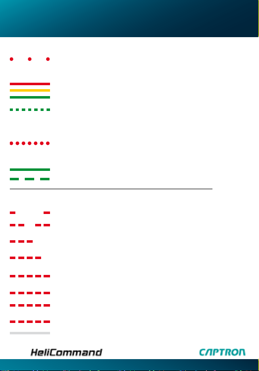
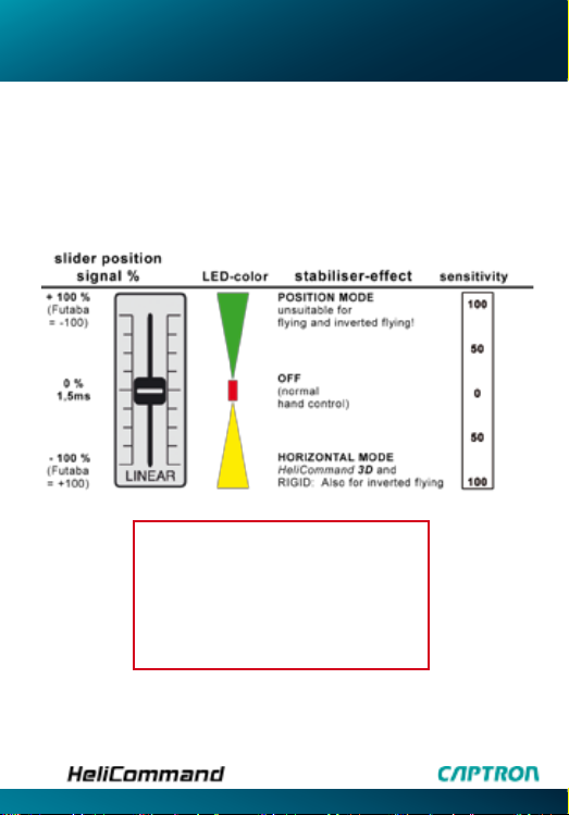
LED red = stabilising functions switched off (= conventional)
LED yellow = horizontal mode
LED green = position mode
Horizontal mode („yellow“): moves the helicopter to the horizontal attitude if you
release the aileron (roll-axis) and elevator (pitch-axis) controls.
This works totally independently of the optical quality of the ground surface. For
indoor ying you should select this mode; if you do not wish to, please read the
notes on page 29.
Position mode („green“): in this mode the unit stabilises the model’s position as
well as its horizontal attitude. This is the most powerful stabilisation, and is ideal
for “automatic” hovering and slow circuits. It works most effectively at heights of
about 0.5 to 2 metres above a natural surface (grass, gravel etc.). If you release
the aileron and elevator controls, the system actively brakes the helicopter until it
is stationary; all the pilot has to control is the collective
pitch / throttle function. If the model exhibits any slow drift at the hover, this can
very easily be corrected manually. For slow circuits close to the ground, you can
set a forward speed by keeping a slight constant push on the elevator stick, then
direct the model using the tail rotor stick (just like steering a car).
For higher speed and for ying at heights above about 5 m, this mode would
tend to be a nuisance because of its corrective actions; in this case you should
switch to horizontal mode („yellow“).
The conguration for the above-described functions is possible without PC,
unless four head-servos are used.
RIGID mode: this is a fourth mode of operation only available with the
HeliCommand RIGID: it is designed for ybar-less rotor heads, stabilising and
maintaining the helicopter’s attitude (see page 5).
Rigid mode can be combined to working parallel with the three modes
described above. These options are explained on page 26.
In addition to the previously described stabilising functions, all HeliCommand
versions offer the following supplementary functions:
swashplate mixer, tail rotor gyro and automatic trim.
Description of facilities

Pilot channel
10
We recommend that you use this auxiliary channel as it enables you to switch
between the three modes, and also to set the desired stabilisation power.
It is advisable to use a slider or a three-position switch with selectable output
values for the pilot channel. If the pilot channel is not connected to the recei-
ver, a pre-set value applies which is: position mode with a setting of +70%;
this is a suitable setting for many models, and can be changed to any value
you like using the PC adaptor. .
You may of course exchange up with down side, by reversing transmitter
setting or slider mounting.
Slider more towards the center
reduces the sensor gain and slows
down the corrections.
Additionally, the auto pilot can be
overridden by smaller stick deections.

Tail rotor gyro
11
The HeliCommand features an integral gyro which can be operated in either
normal or heading-lock mode (with AVCS). Use high-speed digital servos for
best performance. Not suitable for “narrow-pulse”-servos.
A second auxiliary channel (“AUX channel”) is used to adjust the gain setting,
and to switch between heading-lock and normal mode.
If the AUX channel is not connected to the receiver, the internal default setting
applies. This is heading hold mode set to about +65%; it can be adjusted
using the PC adaptor.
Further adjustments can be made using the PC adaptor, e.g. travel limiting
and collective pitch > tail rotor mixing; the latter is mixed in after the gyro, and
therefore also works in heading lock mode.
The versions 3D and Rigid provide additional „expert“ adjustments e.g. delay
and “hold“- range“.
If you do not wish to use the integral gyro, an external gyro can be connected
directly to the receiver. In this case please note the following points:
1. turn rates above 400° / sec. are not allowed, since they might seriously
disturb the stabilisation system.
2. you subsequently decide to use the internal gyro, you must rst erase any
internal auto-trim values, and check the sensor direction of the gyro.

Automatic trim
12
This is recommended, but is not absolutely essential. Auto-trim works independently
of the auto-pilot, and makes life considerably easier for beginner and
pro-pilot alike. To use it, your transmitter needs a momentary (self-centring) button or
a toggle switch, assigned to an auxiliary channel. Many transmitters feature a Trainer
switch which can be re-programmed for this purpose. The AUX channel has to be
congured as the trim function using a PC. When the model is ying, a brief button-
press is sufcient to generate the trims automatically for
aileron, elevator and rudder (tail rotor). The settings are stored in the unit, but can be
revised at any time. The automatic trim function requires around eight
seconds of steady hovering in order to record the correct trim values; they can
then be called up immediately by pressing the trim button. Automatic trim can also
improve the performance of the integral tail rotor gyro if the neutral pitch angle of the
tail rotor blades is not adjusted properly. Independently of this, the tail gyro has once
to be adjusted manually, see page 30! To activate auto-trim, the AUX channel has to
be congured as the trim input using the PC adaptor. The trim is then triggered by
switching the AUX signal to +100% (> approx. 60%) (note that in Futaba transmitters
„-100%“ means „+ 100%“ and vice versa).
The LED ickers red to indicate while auto-trim is being sent. The AUX-channel, if
assigned to auto trim, will still switch off the heading-hold-mode by a negative signal
-100% (< -60%), but Gyro gain (sensitivity) has to be set by PC only. Thus a gyro-mo-
de-switch can be combined into the same channel (e.g. by ight state programming).
If you wish heading-hold, then the AUX channel must not send a negative signal; the
trim switch should only switch between zero and +100% (Futaba = -100%). Note that
the trim channel must not be assigned to any other transmitter control actions which
you may have programmed, as you might then trigger auto-trim accidentally. The trim
switch should only be operated with the model in ight (unlike the SET-button).
For erasing the internal auto-trim values: call up the set-up mode (page 23), and then
switch on again.
Fail-safe
If you are using an FM / PPM system without own failsafe function, the auto-pilot im-
mediately responds to a radio link failure by carrying out the following actions: aileron,
elevator, tail rotor to neutral, collective pitch to the last received position, stabilisation
to position mode, set to 65%. Receivers with integral failsafe function should explicitly
be programmed to the mentioned positions. For optimum security we recommend the
use of PCM systems.

13
HeliCommand 3D
This version stabilises both the normal ight attitude and the inverted ight
attitude. (In inverted ight this is limited to horizontal stabilisation („yellow“),
because position holding („green“) requires a visual link between the
CCD sensor and the ground. Even so, this is sufcient to make inverted hovering
and aerobatics very much easier.) Adjustments are done the same way as with
the HeliCommand 3A. More adjustments are optionally available via PC.
The system does include optical interference suppression for situations
where the CCD sensor is directed towards the sky, but for safety’s sake the
stabilisation mode should always be switched from „green“ to „yellow“ before
you start a session of aerobatics or inverted ight. This is particularly important
for indoor ying, but also for high-speed circuits and ying at fairly high altitudes.
Additional important notes: see “Tips on ying”, page 32
HeliCommand RIGID
If your rotor head has no ybar, you must use the HeliCommand RIGID, and
you must activate RIGID mode.
If not, the stabilisation may not work properly due to the occuring turn rates!
All the RIGID-Mode set-up functions can be accessed using the PC adaptor;
they are explained in detail in the HeliCommand set-up software; once you
have selected HeliCommand RIGID as the device type. If you do not change
the set-up using the PC adaptor, the HeliCommand RIGID behaves exactly like
the HeliCommand 3D (page 27).
HeliCommand Pro
The professional version of the HeliCommand is designed for particularly
valuable model helicopters as well as for industrial helicopters and commercial
applications such as lming, still photography, surveying etc. It is designed for
maximum possible precision, and features important supplementary airborne
instruments and other features including auxiliary optics for redundant drift
detection, greater ight altitudes and altitude stabilisation.
For more information please visit: www.helicommand.com
The upgrade versions of HeliCommand

Survey - the essentials
14
The unit is as simple as we could make it in terms of setting-up and ying.
However, if you are a beginner to helicopters it is really essential to ask a friend
with experience of ying these machines to help you at the initial test-ying
stage, as the functions of a helicopter are very complex.
This double page and all the points marked with an exclamation mark
are particularly important, and should be read carefully even by pro-standard
pilots.
Installation
• Mount only by using the supplied self-adhesive soft foam stripes, strictly
according to the instructions (pages 16-18).
• An electrical connection must be created as an earth between the tail boom,
the motor crankcase and the helicopter chassis.
• The higher in the model the unit is installed, the smoother the stabilisation in
position mode when close to the ground.
• Please ensure that the unit is set vertically, securely xed in the model, and
with an absolutely unobstructed view between the sensor and the ground.
• Important notes for internal-combustion helicopters and comprehensive
installation tips: see page 19.
Transmitter
All the mixer functions for elevator, aileron and tail rotor must be disabled: al-
ways set single-servo mode (H1 or CCPM), as the HeliCommand is designed
to use its own internal mixer exclusively.
Conguration
The unit must be congured in order to match it to the model and the
RC system; this only needs to be carried out once (page 23).
If the standard default settings suit your model and RC system (page 22) this
setup can be omitted.
Before the rst ight with the system it is essential to check the controls and
sensor directions on all three axes! (page 28)

15
Switching on
When the HeliCommand is switched on, it carries out a self-test (LED ashes 8
x). During this period the helicopter must be standing horizontal and must be left
untouched. LED ashes red continuously: error message (page 8)
Take-off
Don’t take the model off before the servos are responding to the controls!
It is important to check the controls because the throttle servo or speed
controller would respond to the transmitter even if all the other servos were
not yet receiving a signal; this might be because the self-test is still running, or
because an error has been detected.
Flying
Please observe the safety measures (page 36) at all times.
In particular, never take your eyes off the helicopter in the air even when
position mode is switched on, as occasional drift or interference inuences may
occur at any time without warning.
• Indoor ying: please be sure to read the notes on page 33
• Do not y inverted or attempt aerobatics (3D) with the 3A version;
see page 34
• Models without a ybar can only be stabilised using the RIGID version, and
only then if RIGID mode is activated; see page 34
• Even though the system incorporates integral fail-safe and stabilisation
circuits, it is not capable of avoiding all crashes caused by radio interference,
other transmitters etc. We recommend that you use a PCM system, and check
the aerial deployment in the model very carefully.
• Severe stress, vibration and ageing will eventually take their toll on system
accuracy, and may require a readjustment of the internal calibrations and
temperature compensation values if good precision is to be maintained.
This work can be carried out by any Robbe Service Centre.

Installation
16

17
An electrical connection must be created as an earth between the tail boom,
the motor crankcase and the helicopter chassis. Note that carbon is a
conductive material! Belt drives inside the tail boom are particularly dangerous,
as they act as a high voltagte generator. Cables running along the tail boom
may conduct sparks to receiver and servos.
On-board location
The mounting surface should be solid and should not “give”, as this could ge-
nerate resonance effects.For Position mode: the higher the installation loca-
tion in the model, the smoother the stabilisation effect in position mode at low
altitude, and the larger the possible gain setting you can safely use. In many
models a suitable location is one side of the tail rotor servo, or - using the
mounting bracket supplied - the tail boom, the tail rotor servo, the chassis or
the fuselage nose.
Installed attitude
Vertical, with optical sensor facing down.
Any of the four possible directions can be used.
Unobstructed view between the sensor and the ground
The cross-section of the vision cone is square, with an open angle of 15° x 15°.
For this reason you must arrange an unobstructed square vertically below the
sensor, with at least the side length of (safety tolerance included)
S = window size (15mm) + [0,28 * distance from window]
(see drawing on the left side).
It is important that neither the aerial wire nor anything else can get in the way
of the vision beam!
Installation in an enclosed fuselage
Cut an opening in the fuselage (see above for size); alternatively do not cut a
hole (no sensor view), and manage without position mode. In this case cover
the sensor window with dark adhesive tape.
If you do this, you can only exploit horizontal mode, and not position mode.
Electrical earth

18
In case of a vertical mounted tail servo, you can stick the HeliCommand
to the tail rotor servo case (with foam tape) without using the mount-
ing bracket. Alternatively, for maximum distance to ground and espe-
cially with small models, it makes sense to install the unit as high as
possible. This means: as close as possible under the ybar, with a safety mar-
gin for maximum ybar travel.
The mounting bracket supplied can often be xed to the top of the tail rotor
servo or some other support. Do not use foam under the bracket, x the
bracket rigidly.
Mounting the unit on the tail boom
Fix the supplied mounting bracket to the tail boom using a cable tie, pulling
it really tight. The HeliCommand can then be xed to the bracket by applying
two strips of double-sided foam tape to the back of the unit. Once test-ying
is complete, secure it against rotation relative to the boom, using UHU-hart or
cyano-acrylate glue. Double-sided foam tape is too soft for this purpose.
Protect from vibration
Please take particular care to protect the unit from vibration!
Always use the supplied special soft self-adhesive foam tape, and only two nar-
row strips right along the top and bottom edges of the back panel. This means
that the mounting surface must be at least as tall as the HeliCommand itself.
Do not apply anything which might constrain the special damping features
of the supplied foam tape.
Remove all traces of oil residue before sticking the unit in place, in order to
ensure that the HeliCommand cannot shift or come loose, as this could cause
the model to take up an inclined attitude in stabilisation mode, rendering it
uncontrollable.
(If you fear that the self-adhesive foam tape could be coming loose, we recom-
mend to wrap a thin rubber band around the HeliCommand. The band must be soft
enough so that it will not press the foam strips essentially thinner than they are).
Mounting the unit on the tail rotor servo

19
Horizontal attitude
Set the unit as close to vertical as possible, i.e. parallel to the main rotor shaft!
The electronic compensation means that an angled installation would only be
noticeable when the pilot gives a tail rotor command.
Miniature helicopters with particularly large blade pitch angles invariably hover
with a more pronounced tilt; this is necessary to counter-act for the greater tail
rotor thrust. You can compensate for this tilt using the PC adaptor, or see the
page 38: „fault-nding“.
Notes regarding internal combustion engines
• The unit must be installed as far from the exhaust as possible.
• Effective vibration protection is very important, as invisible vibration from the
engine can be a particular problem. If you can feel the HeliCommand unit
vibrating when the engine is running, even though it is installed as directed,
we recommend additional vibration damping measures.
The safest option is a metal plate (3 mm aluminium or 1.5 mm steel) which
is rst stuck to the HeliCommand; the foam strips are then applied between
this plate and the mounting surface. Additionally secure the HeliCommand
with thin soft rubber band.
Alternatively you could consider installing the unit in a different location,
where vibration is not so severe.
• Avoid running the motor unnecessarily rich, to avoid clouds of smoke
confusing the sensor.
• To prevent soiling we recommend that you install a protective tube, or (better)
a cubic box under the sensor. Its internal dimensions must take the vision
cone into account. Be sure to clean the window regularly right to the edges.

20
All modern radio control systems include helicopter mixers which
ensure that the servos move as required, for example, the superimposed servo
movements required for a three-point swashplate linkage. However, when the
HeliCommand is used, the mixing must be carried out using the unit’s integral mi-
xer. For this reason please select an unmixed helicopter program (“H1” / CCPM
/ single servo) at your transmitter, so that only one servo moves when you move
any transmitter stick in any single plane. Once this is the case, you can start
connecting the system. If you are not sure how to set up the radio control system,
please ask the transmitter manufacturer. Alternatively - if a throttle curve is not
required - select a standard (base) program instead of a helicopter program. This
also guarantees that the signals from the auxiliary channel sliders and switches
are also transferred without any mixing. Attention: if using an H4 swashplate
linkage, the PC adaptor is necessary.
Connections
aileron/roll
elevator
coll. pitch
tail/yaw
PILOT
AUX
90° with
45° offset
-
battery
aileron/roll
elevator
coll. pitch
tail servo
(H1)
single servo
RC-Modul
receiver
SET
LED
serial interface
left*-front
right*-back
left*-back
tail servo
right*-front
battery
15
32
120° or 90°
left* servo
right* servo
elevator
tail servo
-
battery
12
3
PC-Adapter
Each input cable has its
defined function and has
to be connected to the
particular output of the
reciever which transfers the
assigned control function
without any mixing.
x
Internal mixer;
therefore the
channels will, in
general, not be
passed through
directly.
Note the servo assignment
according to the type of
swashplate linkage.
*) If the swashplate moves downward for increase of
coll. pitch, swap connections of right and left servo(s).
flight
direction
Table of contents