Car-O-Liner Group AB Quick 42
240724, EN- rev. 8, 2017-09
Foreword
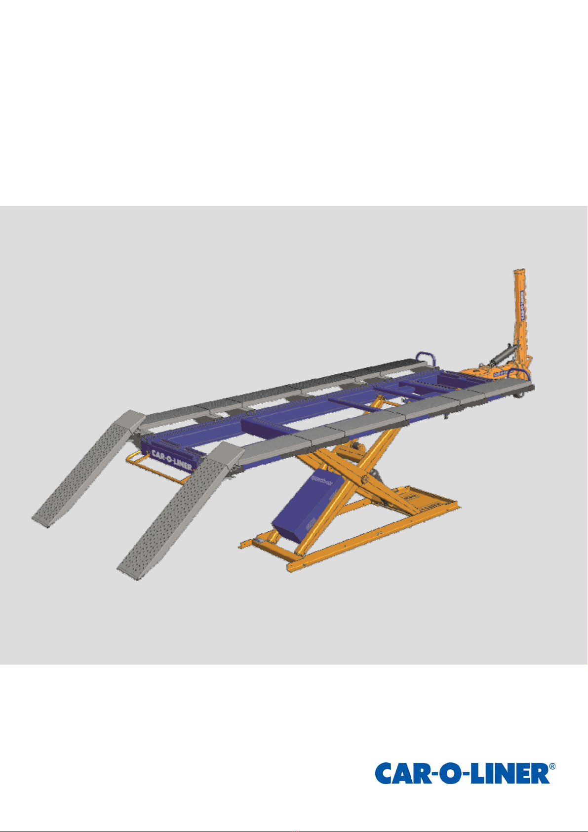
This equipment is used to facilitate high quality repairs
to collision-damaged vehicles. All other use of the
equipment, or use that is contrary to the instructions in
this manual, can cause personal injury and/or equipment
damage.
Car-O-Liner Group AB including any company within
the Car-O-Liner Group of companies ("Car-O-Liner")
can not be held responsible for any claims for loss or
damages as a result from incorrect use of this equipment
or its use in a manner not intended. Save for product
liability claims for loss or damages as a result of per-
sonal injury or damage to property to the extent caused
by the negligence, gross negligence, breach of contract,
or other wrongdoing of Car-O-Liner (as prescribed by
the Product Liability Act (1992:18) or similar legisla-
tion applicable on other markets),
Car-O-Liner shall in no event be liable for any loss or
damage to revenues, profits or goodwill or other special,
incidental, indirect or consequential damages of any
kind.
Warranty
Car-O-Liner offers a one-year limited guarantee from
the date of installation of the equipment at end users
premises. This guarantee covers only material defects
and assumes normal care and maintenance according to
Car-O-Liner specification.
The guarantee assumes that:
The equipment is correctly installed and inspected in
accordance with current local laws and regulations.
The equipment has not been altered or rebuilt with-
out prior written approval from Car-O-Liner.
Genuine Car-O-Liner spare parts are used in any
repairs and conducted by Car-O-Liner certified tech-
nician.
Operation and maintenance have been carried out
according to the instructions in this manual.
All claims on warranty shall be notified through your
authorized Car-O-Liner Distributor by use of
Car-O-Liner´s VisionWeb platform without undue delay
and shall verify that the fault has occurred within the
guarantee period and that the unit has been used within
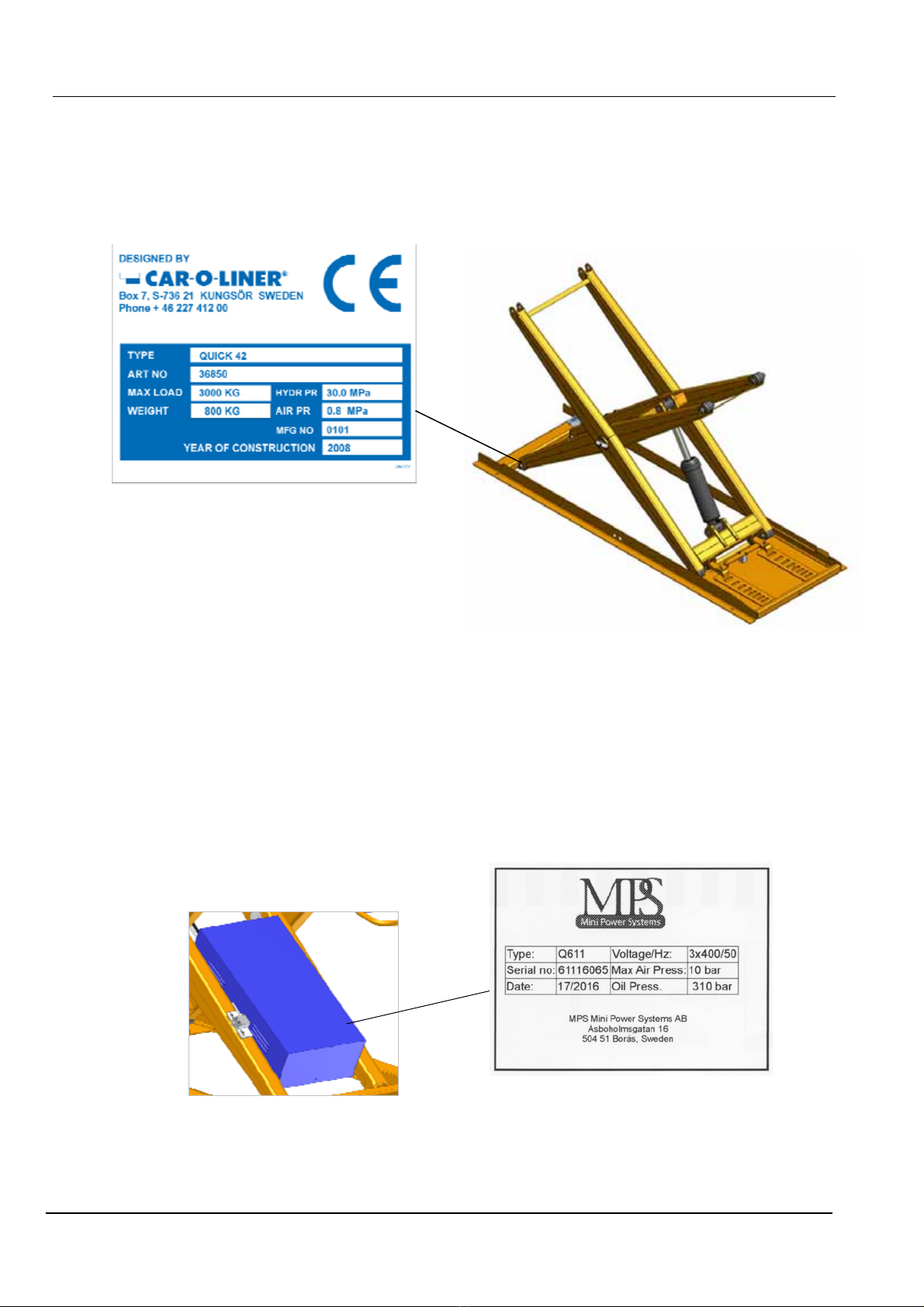
its operating range as stated in the specifications. All
claims shall include the product type and article number
as well as a detailed description of the problem and ac-
tions taken trying to solve it. This data is stamped on the
name plate (refer to section 1.2 "Marking" for location).
Note
This instruction manual provides advice as well as in-
structions for installation, operation, maintenance and
trouble shooting.
IMPORTANT! Read this manual carefully to become
familiar with the proper operation of the equipment.
It is recommended that you use your authorized
Car-O-Liner Distributor for maintaining, servicing and
upgrading your products. Never perform repairs, ad-
justments or any other work on the products which may
result in personal injury and damage to the product.
Your Car-O-Liner Distributor employs factory trained
technicians and is focused on offering you the best over-
all experience with your new Car-O-Liner product. Any
revisions or upgrades of the products, as required by
Car-O-Liner, shall be performed by your authorized
Car-O-Liner Distributor.
The photographs and drawings in this manual are in-
tended only to be illustrative and do not necessarily
show the design of the equipment available on the mar-
ket at any given time. The equipment is intended for use
in accordance with current trade practice, applicable
laws and safety regulations. The equipment illustrated in
the manual may be changed without prior notice.
The contents in this publication can be changed without
prior notice.
This publication contains information which is protected
by copyright laws. No part of this publication may be
reproduced, stored in a system for information retrieval
or be transmitted in any form, in any manner, without
Car-O-Liner’s prior written consent.
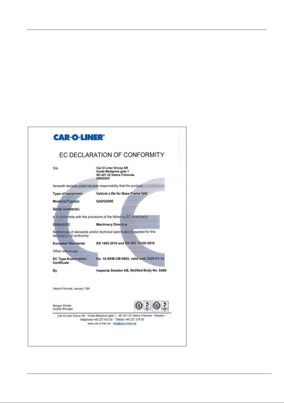
Conformity with directives and standards
The equipment is designed and manufactured by Car-O-
Liner, which is an EN-ISO 9001 and 14001 accredited
development and manufacturing organisation.
The equipment is CE-approved by Inspecta, Sweden. It
is required that only Car-O-Liner approved spare parts
and accessories are used with the equipment.
Copyright ©Car-O-Liner AB, 2012