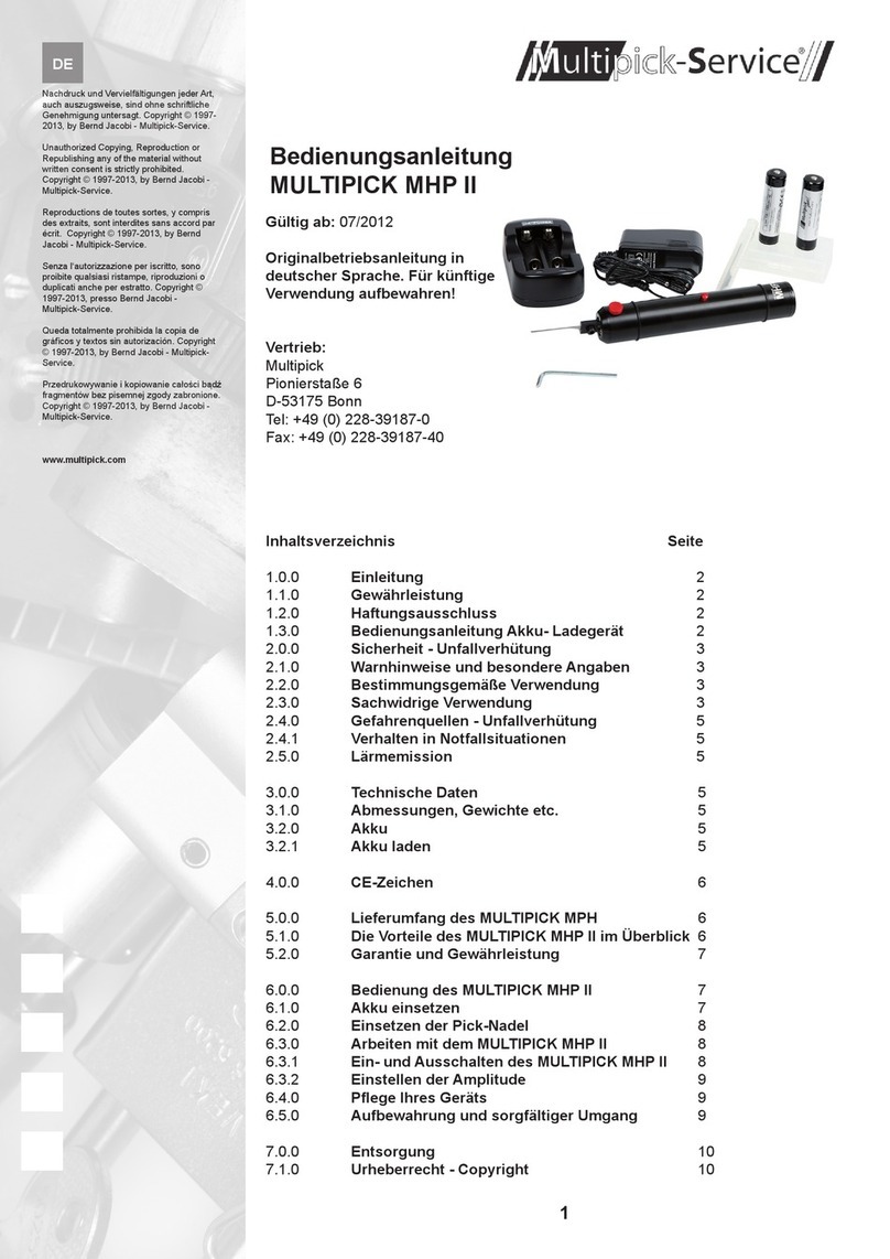
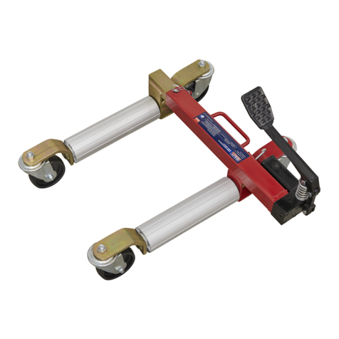
Mityvac MVA6832 User manual

USER’S MANUAL
Have Technical Questions?
If you have questions, or require techni-
cal service, please contact our trained
service technicians at:
1-314-679-4200 ext. 4782
Monday - Friday 7:30 am to 4:15 pm
CST
Visit our website at www.mityvac.com for
new products, catalogs and instructions
for product use.
Need Service Parts?
To order replacement or service parts,
visit us online at
www.mityvacparts.com
or call toll free 1-800-992-9898.
Reservoir Specifications
Capacity: 40 ounces (1200 milliliters)
Page
Section - MV33 - 1A
Form 823617
JULY - 2005
©
© Indicates change
CLAMP-ON
AUTO-REFILL KIT
MODEL MVA6832
©

Page Number - 2 Form 823617
Important Precautions
· Brake fluid is highly corrosive.
Wear gloves and approved safety
goggles at all times, and prevent
contact of the fluid with painted
surfaces.
· Consult and follow the vehicle
manufacturer’s recommended
procedures when servicing any
hydraulic system.
· Properly dispose of old fluids, and
replenish hydraulic systems with
new brake fluid from freshly opened
containers.
Principle of Operation
This unit is designed to automatically
maintain the level of new brake fluid
in the master or slave cylinder of a hy-
draulic brake or clutch system while the
system is bled manually or by vacuum.
Fluid flows from a reservoir into the
master cylinder by means of a tube and
base. The unit has a ¼ turn valve for
turning the flow on or off, and means for
adjusting the level of fluid in the master
cylinder. A 40 oz (1200 ml) reservoir is
included for use when dispensing fluids
from bulk containers. Two adapter caps
are also included, which allow direct ad-
aptation of standard 12 oz. and 32 oz.
brake fluid bottles to the valve assembly
and base.
Instructions for use
Important: This unit is designed for
servicing a variety of vehicles in a
safe, convenient manner. However,
the varying shapes, sizes, designs and
locations of master cylinders prevent its
use on every vehicle and application.
Check the unique design and location
of your master cylinder prior to proceed-
ing with the following instructions.
1. Fill the 40 oz (1200 ml) reservoir
with vehicle manufacturer’s recom-
mended brake fluid, to a level
exceeding the amount of fluid to be
bled (Fig 1), and install the lid. Or,
remove the lid from a standard new
12 oz. or 32 oz. bottle of brake fluid,
and thread on the appropriate size
Adapter Cap.
2. Clean the exterior of the master
cylinder and master cylinder cap
to prevent dirt from entering the
master cylinder when the cap is
removed.
3. Remove the cap from the master
cylinder, and set the Refill Base
onto the neck of the master cylinder.
4. Clamp the base to the neck of the
master cylinder by tightening the
Sliding Block Knob (Fig 2).
5. Install the Adjustment Spring onto
the neck of the Valve Assembly as
shown (Fig 3).
6. Slide the neck of the Valve As-
sembly through the hole in the
Refill Base, and use the Adjustment
Spring to align the bottom of the
neck with the MAX fill line on the
master cylinder (Fig 3).
7. Remove the Valve Assembly from
the base and insert it into the lid
of the pre-filled Reservoir Bottle or
into the Adapter Cap installed on a
bottle of brake fluid (Fig 4).
8. CHECK TO ENSURE THAT THE
VALVE IS IN THE “CLOSED” POSI-
TION.
9. Turn over the reservoir/bottle and
valve assembly, and insert it back
into the Refill Base (Fig 5).
10. Open the valve to allow fluid to flow
into the master cylinder. Leave
the valve open while bleeding the
hydraulic system, and the unit will
automatically maintain the level of
fluid at the MAX fill line.

Page Number - 3
Form 823617
Figure 1.

Page Number - 4 Form 823617
Figure 2
Figure 3
© Indicates change
©

Page Number - 5
Form 823617
Figure 4
Figure 5
BRAKE
FLUID
© Indicates change
©
©

Page Number - 6 Form 823617
Model MVA6832 Service Items
Item Part No. Description
1 823560 Valve Kit
2 823561 Refill Base Kit
3 823562 Cap Kit
4 823563 Bottle Kit
© Indicates change
©

Page Number - 7
Form 823617
Lincoln Industrial Standard Warranty
LIMITED WARRANTY
Lincoln warrants the equipment manufactured and supplied by Lincoln to be free from defects in material
and workmanship for a period of one (1) year following the date of purchase, excluding there from any
special, extended, or limited warranty published by Lincoln. If equipment is determined to be defective
during this warranty period, it will be repaired or replaced, within Lincoln’s sole discretion, without charge.
This warranty is conditioned upon the determination of a Lincoln authorized representative that the
equipment is defective. To obtain repair or replacement, you must ship the equipment, transportation
charges prepaid, with proof of purchase to a Lincoln Authorized Warranty and Service Center within the
warranty period.
This warranty is extended to the original retail purchaser only. This warranty does not apply to equipment
damaged from accident, overload, abuse, misuse, negligence, faulty installation or abrasive or corrosive
material, equipment that has been altered, or equipment repaired by anyone not authorized by Lincoln.
This warranty applies only to equipment installed, operated and maintained in strict accordance with the
written specifications and recommendations provided by Lincoln or its authorized field personnel.
THIS WARRANTY IS EXCLUSIVE AND IS IN LIEU OF ANY OTHER WARRANTIES, EXPRESS
OR IMPLIED, INCLUDING, BUT NOT LIMITED TO, THE WARRANTY OF MERCHANTIBILITY OR
WARRANTY OF FITNESS FOR A PARTICULAR PURPOSE.
In no event shall Lincoln be liable for incidental or consequential damages. Lincoln’s liability for any claim
for loss or damages arising out of the sale, resale or use of any Lincoln equipment shall in no event exceed
the purchase price. Some jurisdictions do not allow the exclusion or limitation of incidental or consequential
damages, therefore the above limitation or exclusion may not apply to you.
This warranty gives you specific legal rights. You may also have other rights that vary by jurisdiction.
Customers not located in the Western Hemisphere or East Asia: Please contact Lincoln GmbH & Co. KG,
Walldorf, Germany, for your warranty rights.
Lincoln Industrial Contact Information
To find Lincoln Industrial’s Nearest Service Center call the following numbers, or you may also use our
website
Customer Service 314-679-4200
Website lincolnindustrial.com

Page Number - 8 Form 823617
Americas:
One Lincoln Way
St. Louis, MO 63120-1578
USA
Phone +1.314.679.4200
Fax +1.800.424.5359
Europe/Africa:
Heinrich-Hertz-Str 2-8
D-69183 Walldorf
Germany
Phone +49.6227.33.0
Fax +49.6227.33.259
Asia/Pacific:
51 Changi Business Park
Central 2
#09-06 THe Signature
Singapore 486066
Phone +65.6588.0188
Fax +65.6588.3438
© Copyright 2004
Printed in USA
Web site:
www.lincolnindustrial.com
Declaration of Conformity as defined by Machinery
Directive 98/37/EG Annex II A
This is to declare that the design of the
Brake Refill Kits for MityVac products (Clamp-On & Plate Style)
in the version supplied by Lincoln Industrial, comples with provisions of
the Directives 98/37/EG.
Applied harmonized standards in particular:
EN 292-1 Safety of Machinery Part 1 Basic Terminology, Methodology.
EN 292-2 Safety of Machinery Part 2 Technical Principles and specifica-
tions.EN 809 Pumps and Pump Units for Liquids Safety Requirements.
St. Louis, MO 3/7/05 Ayzik Grach, Manager, Product Engineering

Numéro de Page - 9
Formulaire 823617
KIT DE REMPLISSAGE
AUTOMATIQUE
SERRE TUBE
MODELE MVA6832
Page
Section - MV33 - 1A
Formulaire 823617
JUILLET - 2005
MODE D’EMPLOI
Vous Avez des Questions Tech-
niques ?
Si vous avez des questions ou
vous avez besoin de support
technique, merci de bien vouloir
appeler nos techniciens au :
1-314-679-4200 poste 4782
Du lundi au vendredi de 7:30 à
16:15 CST
Allez sur notre site Internet
www.mityvac.com pour voir les
nouveaux produits, les cata-
logues et les modes d’emploi.
Vous Avez Besoin de Pièces
Détachées ?
Pour commander des pièces
de rechange ou des pièces
détachées, allez sur notre site
Internet www.mityvacparts.com
ou appelez notre numéro vert
au 1-800-992-9898.
Caractéristiques Techniques du
Réservoir:
Contenance : 1200 millilitres (40
onces)
© Indique le changement
©

Numéro de Page - 10 Formulaire 823617
Précautions Importantes
Le liquide de frein est extrêmement
corrosif.
Porter des gants et des lunettes de
sécurité autorisées tout le temps et
éviter que le liquide touche les surfaces
peintes.
Se référer et suivre les procédures
recommandées par le fabricant du
véhicule lors de l’entretient du système
hydraulique.
Disposer des liquides usagés de façon
appropriée et remplir les systèmes hy-
drauliques avec du liquide de frein neuf
provenant d’une bouteille récemment
ouverte.
Principe de fonctionnement
Cet équipement est conçu pour main-
tenir automatiquement le niveau de
liquide de frein neuf dans le maître-
cylindre ou dans le cylindre asservi
du système de freins hydrauliques ou
d’embrayage lorsque le système est
purgé de façon manuelle ou par le vide.
Le liquide va d’un réservoir au maître-
cylindre par l’intermédiaire d’un tube et
d’une base. Cet équipement comprend
une valve à ¼ de tour pour ouvrir ou
fermer l’arrivée de liquide et cette valve
est utilisée pour ajuster le niveau de
liquide dans le maître-cylindre. Un rés-
ervoir de 1200 millilitres (40 onces) est
joint pour délivrer des liquides venant
de containeurs en vrac. Deux bouchons
adaptateurs sont aussi joints permettant
de connecter directement les bouteilles
standards de liquide de frein de 12 et 32
onces à la valve et à la base.
Instructions d’utilisation
Important : Cet équipement est conçu
pour l’entretient d’une variété de vé-
hicules de façon sure et commode.
Cependant, les différentes formes,
tailles, designs et emplacements des
maîtres-cylindres font qu’il ne peut pas
être utilisé sur tous les véhicules. Véri-
fiez le design unique et l’emplacement
de votre maître-cylindre avant de
continuer.
1. Remplir le réservoir de 1200 ml
(40 onces) avec du liquide de frein
recommandé par le fabricant du
véhicule jusqu’à atteindre un niveau
de liquide supérieur à celui qui sera
purgé (Figure 1) et installer le cou-
vercle. Ou retirer le couvercle d’une
bouteille standard de liquide de frein
de 12 et 32 onces et visser la sur le
Bouchon Adaptateur d’une taille ap-
propriée.
2. Nettoyer l’extérieur du maître-cylindre
et le bouchon du maître-cylindre pour
empêcher la saleté d’entrer dans le
maître-cylindre lorsque le bouchon
est enlevé.
3. Enlever le bouchon du maître-cyl-
indre et mettre la Base de Remplis-
sage sur le cou du maître-cylindre.
4. Monter la base sur le cou du maître-
cylindre en serrant le Bouton de
Coulisseau (Figure 2).
5. Installer le Ressort d’Ajustement sur
le cou du Corps de la Valve (Figure
3).
6. Faire glisser le cou du Corps de la
Valve dans le trou de la Base de
Remplissage et utiliser le Ressort
d’Ajustement pour aligner le bas du
cou avec la ligne de remplissage
MAX sur le maître-cylindre (Figure 3).
7. Retirer le Corps de la Valve de la
base et insérer le dans le couvercle
de la Bouteille de Réservoir pré rem-
plie ou dans le Bouchon Adaptateur
installé sur la bouteille de liquide de
frein (Figure 4).
8. VERIFIER QUE LA VALVE EST EN
POSITION FERMEE.
9. Retourner le réservoir/bouteille et le
corps de la valve et insérer dans la
Base de Remplissage (Figure 5).
10. Ouvrir la valve pour laisser le liquide
couler dans le maître-cylindre.
Laisser la valve ouverte durant la
purge du système hydraulique et
l’équipement maintiendra automa-
tiquement le niveau de liquide à la
ligne de remplissage MAX.
Numéro de Page - 11
Formulaire 823617
Figure 1.
LIQUIDE
DE FREIN

Numéro de Page - 12 Formulaire 823617
Figure 2
Figure 3
© Indique le changement
©

Numéro de Page - 13
Formulaire 823617
Figure 4
Figure 5
© Indique le changement
©
©

Numéro de Page - 14 Formulaire 823617
Pièces Détachées Modèle MVA6832
Pièce Code Article Description
1 823560 Kit Valve
2 823561 Kit Base de Remplissage
3 823562 Kit Bouchon
4 823563 Kit Bouteille
© Indique le changement
©

Numéro de Page - 15
Formulaire 823617
La Garantie Standard de Lincoln Industrial
GARANTIE LIMITEE
Lincoln garantit que l’équipement qu’il fabrique et fournit est sans vice de matériau ou de fab-
rication durant une période d’un (1) an après la date d’achat, sauf si cet équipement est sous
garantie spéciale, prolongée ou limitée publiée par Lincoln. Si l’équipement s’avère défectueux
durant cette période de garantie, celui-ci sera réparé ou remplacé, à la discrétion de Lincoln,
sans frais.
Cette garantie ne s’applique que si un représentant autorisé de Lincoln juge que l’équipement
est défectueux. Pour faire réparer ou remplacer votre équipement, vous devez l’expédier tous
frais de port payés, avec preuve de date d’achat, au centre de service après-vente autorisé
Lincoln durant la période de garantie.
Cette garantie ne couvre que l’acheteur originel. Elle ne couvre pas tout équipement endom-
magé durant un accident, surcharge, abus, négligence, installation défectueuse ou matériaux
abrasifs ou corrosifs. Cette garantie ne couvre pas tout équipement qui a été altéré ou réparé
par toute personne qui ne soit pas autorisée par Lincoln. Cette garantie ne s’applique qu’à
l’équipement installé et utilisé suivant les recommandations écrites de Lincoln ou de son per-
sonnel autorisé itinérant.
CETTE GARANTIE EST EXCLUSIVE ET TENANT POUR TOUTES AUTRES GARANTIES
EXPRESSES OU TACITES, Y COMPRIS, MAIS NON LIMITE A, LA GARANTIE DE QUALITE
MARCHANDE OU LA GARANTIE D’APTITUDE POUR UNE RAISON PARTICULIERE.
Lincoln n’est en aucun cas responsable pour les dommages accessoires ou indirects. La
responsabilité de Lincoln ne peut excéder le prix d’achat en cas de perte ou de dommages
du à la vente, revente ou utilisation de l’équipement. Certaines juridictions n’acceptent pas
d’exclusion ou de limitation sur les dommages accessoires ou indirects, aussi les limitations
ci-dessus ne vous concernent pas forcement.
Cette garantie vous donne des droits précis reconnus par la loi. Certaines juridictions peuvent
vous donner d’autres droits.
Pour les clients qui ne se trouvent pas dans l’Hémisphère de l’Ouest ou l’Est de l’Asie : Merci
de bien vouloir contacter Lincoln GmbH & Co. KG, Walldorf, Allemagne pour faire valoir votre
garantie.
Contacter Lincoln Industrial
Pour trouver votre centre de service après-vente Lincoln Industrial le plus proche, appeler un
des numéros suivants, vous pouvez aussi aller sur notre site Internet
Service Après-Vente 314-679-4200
Site Internet lincolnindustrial.com

Numéro de Page - 16 Formulaire 823617
Déclaration de Conformité telle qu’elle est définie par la Di-
rective des Machineries 98/37/EG Annexe II A
Ceci est pour déclarer que le design du
Kits de remplissage de frein pour des produits de MityVac (Bride-Sur
et modèle de plat)
dans la version fournie par Lincoln Industrial est conforme aux provisions
de la Directive 98/37/EG.
Normes Appliquées :
EN 292-1 Sécurité des Machineries Partie 1 Terminologie de Base, Mé-
thodologie.
EN 292-2 Sécurité des Machineries Partie 2 Principes Techniques et
Spécifications.
EN 809 Pompes et Blocs de Pompe pour la Sécurité des Liquides.
St. Louis, MO 07/03/05 Ayzik Grach, Directeur, Produit Engineering
© Copyright 2004
Imprimé aux USA
Site Internet:
www.lincolnindustrial.com
Amériques:
One Lincoln Way
St. Louis, MO 63120-1578
USA
Tel +1.314.679.4200
Fax +1.800.424.5359
Europe/Afrique:
Heinrich-Hertz-Str 2-8
D-69183 Walldorf
Allemagne
Tel +49.6227.33.0
Fax +49.6227.33.259
Asie/Pacifique
51 Changi Business Park
Central 2
#09-06 The Signature
Singapour 486066
Tel +65.6588.0188
Fax +65.6588.3438

Seite - 17
Formular 823617
Seite
Abschnitt - MV33 - 1A
Formular 823617
JULI - 2004
ANKLEMMBARER
AUTOMATISCHER
AUFFÜLLSATZ
Modell MVA6832
BENUTZERHANDBUCH
Haben Sie technische Fragen?
Wenn Sie Fragen haben oder
technischen
Kundendienst brauchen, wenden
Sie sich
bitte an unsere geschulten Kunden-
dienst-
Techniker unter:
1-314-679-4200 Apparat 4782
Montag – Freitag, 7:30 – 16:15
Mittelamerikanische Zeit
Besuchen Sie unsere Website
www.mityvac.com, um Information
über neue Produkte, Kataloge und
Gebrauchsanweisungen zu er-
halten.
Brauchen Sie Ersatzteile?
Zur Bestellung von Ersatz- oder
Wartungsteilen besuchen Sie uns
bitte bei www.mityvacparts.com
oder rufen Sie gebührenfrei 1-800-
992-9898 an.
Behälterspezifikationen
Kapazität: 40 Unzen (1200 ml)
© Zeigt Änderung an
©

Seite - 18 Formular 823617
Wichtige Vorsichtsmaßnahmen
• Bremsflüssigkeit ist stark korrodierend.
Jederzeit Handschuhe und eine zugelas-
sene Sicherheitsbrille tragen und Kontakt
der Flüssigkeit mit lackierten Oberflächen
vermeiden.
• Die vom Fahrzeughersteller empfohlenen
Verfahrensweisen lesen und sie beim
Warten eines Hydrauliksystems befolgen.
• Alte Flüssigkeiten auf angemessene
Weise entsorgen und Hydrauliksysteme
mit frischer Bremsflüssigkeit aus kürzlich
geöffneten Behältern auffüllen.
Betriebsprinzipien
Dieses Gerät behält den Stand der neuen
Bremsflüssigkeit automatisch im Haupt- oder
Nebenzylinder einer hydraulischen Bremse
oder Kupplung bei, während das System
von Hand oder mittels Vakuum geleert wird.
Die Flüssigkeit fließt von einem Behälter in
den Hauptzylinder durch einen Schlauch mit
Auffüllvorrichtung. Das Gerät hat ein Viertels-
drehung - Ventil zum Ein- oder Ausschalten
des Durchflusses, und eine Vorrichtung zum
Einstellen des Flüssigkeitsstandes im Haupt-
zylinder. Ein 40 Unzen (1200 ml) Behälter
wird zur Verwendung bei der Ausgabe von
Flüssigkeiten aus Großmengenbehältern
mitgeliefert. Es werden auch zwei Adapter-
kappen mitgeliefert. Sie erlauben die direkte
Anpassung von Standard 12 Unzen und 32
Unzen Bremsflüssigkeitsflaschen an die Ven-
tilbaugruppe und die Auffüllvorrichtung.
Gebrauchsanweisungen
Wichtig: Dieses Gerät hat den Zweck,
bei der sicheren und praktischen Wartung
einer Reihe von Fahrzeugen behilflich zu
sein. Die verschiedenen Formen, Größen,
Designs und Anbringungsorte von Hauptzyl-
indern verhindern jedoch, dass es an jedem
einzelnen Fahrzeug und für jede Applikation
verwendet werden kann. Vor Beginn der
instruktionsgemäßen Arbeit das individuelle
Design und die Lage des Hauptzylinders
prüfen.
1. Den 40 Unzen (1200 ml) Behälter mit
vom Fahrzeughersteller empfohlener
Bremsflüssigkeit zu einem höheren Stand
auffüllen als Flüssigkeit entnommen
werden soll (Abbildung 1) und die Kappe
anbringen. Oder den Deckel von einer
neuen Standard 12 Unzen oder 32 Unzen
Bremsflüssigkeitsflasche abnehmen und
auf die Adapterkappe der richtigen Größe
aufschrauben.
2. Die Außenseite des Hauptzylinders und
des Hauptzylinderdeckels reinigen, um zu
verhindern, dass Schmutz in den Haupt-
zylinder eindringt, während der Deckel
entfernt ist.
3. Den Deckel vom Hauptzylinder entfernen
und die Auffüllvorrichtung auf den Hals des
Hauptzylinders setzen.
4. Den Fuß an den Hals des Hauptzylinders
klemmen, indem der Schiebeknopf (Ab-
bildung 2) festgezogen wird.
5. Die Einstellungsfeder wie gezeigt auf dem
Hals der Ventilbaugruppe anbringen (Ab-
bildung 3)
6. Den Hals der Ventilbaugruppe durch das
Loch in der Auffüllvorrichtung schieben
und mit der Einstellfeder das Unterteil des
Halses mit der MAX Füllmarke auf dem
Hauptzylinder ausrichten (Abbildung 3).
7. Die Ventilbaugruppe von der Auffüllvor-
richtung nehmen und in den Deckel der
vorgefüllten Behälterflasche oder in die
Adapterkappe einführen, die auf einer
Bremsflüssigkeitsflasche angebracht
wurde (Abbildung 4).
8. SICHERTELLEN, DASS DAS VENTIL IN
DER „GESCHLOSSEN“ POSITION IST.
9. Behälter/Flasche und Ventilbaugruppe
umdrehen und wieder in die Auffüll-vorrich-
tung einführen (Abbildung 5).
10. Das Ventil öffnen, damit die Flüssigkeit
in den Hauptzylinder fließen kann. Das
Ventil offen lassen, während das Hydrau-
liksystem entleert wird, und das Gerät
behält automatisch den Flüssigkeitsstand
an der MAX Füllmarke bei.

Seite - 19
Formular 823617
Abbildung 1

Seite - 20 Formular 823617
Abbildung 2
Abbildung 3
© Zeigt Änderung an
©
Table of contents
Languages:
Other Mityvac Service Equipment manuals