Car Solutions IW04VW-T User manual

Instruction Manual
High-Definition Link for Volkswagen
IW04VW-T
Model Name IW04VW-T
Latest Firmware Date 2015 -12 -21
Manual Version Rev. 1.1
Language English
Release Date: 2016 -06 –28
Car-Solutions.com
www.car-solutions.com

Contents
•Cautions
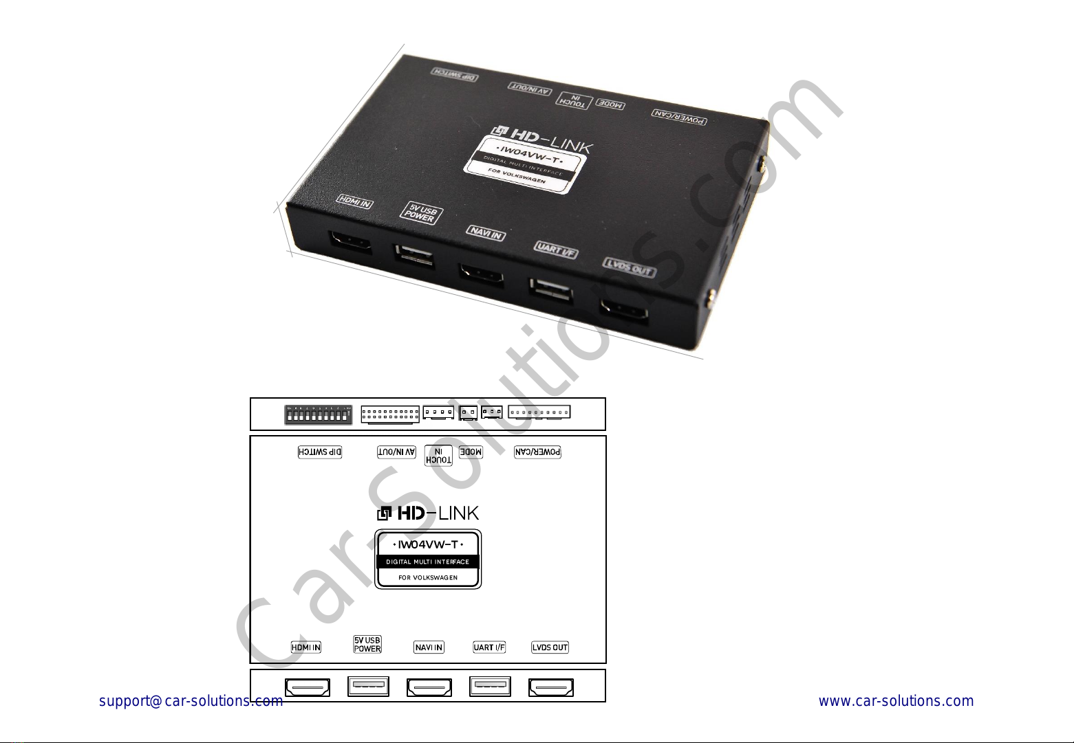
•Dimension & Exterior
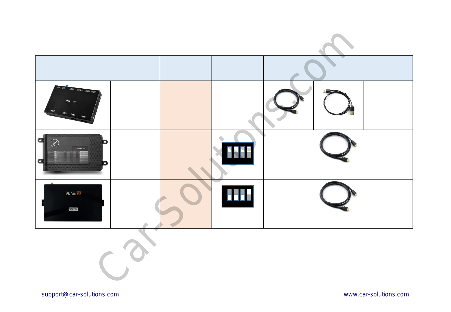
•Components & Optional parts
•Full Installation Diagram
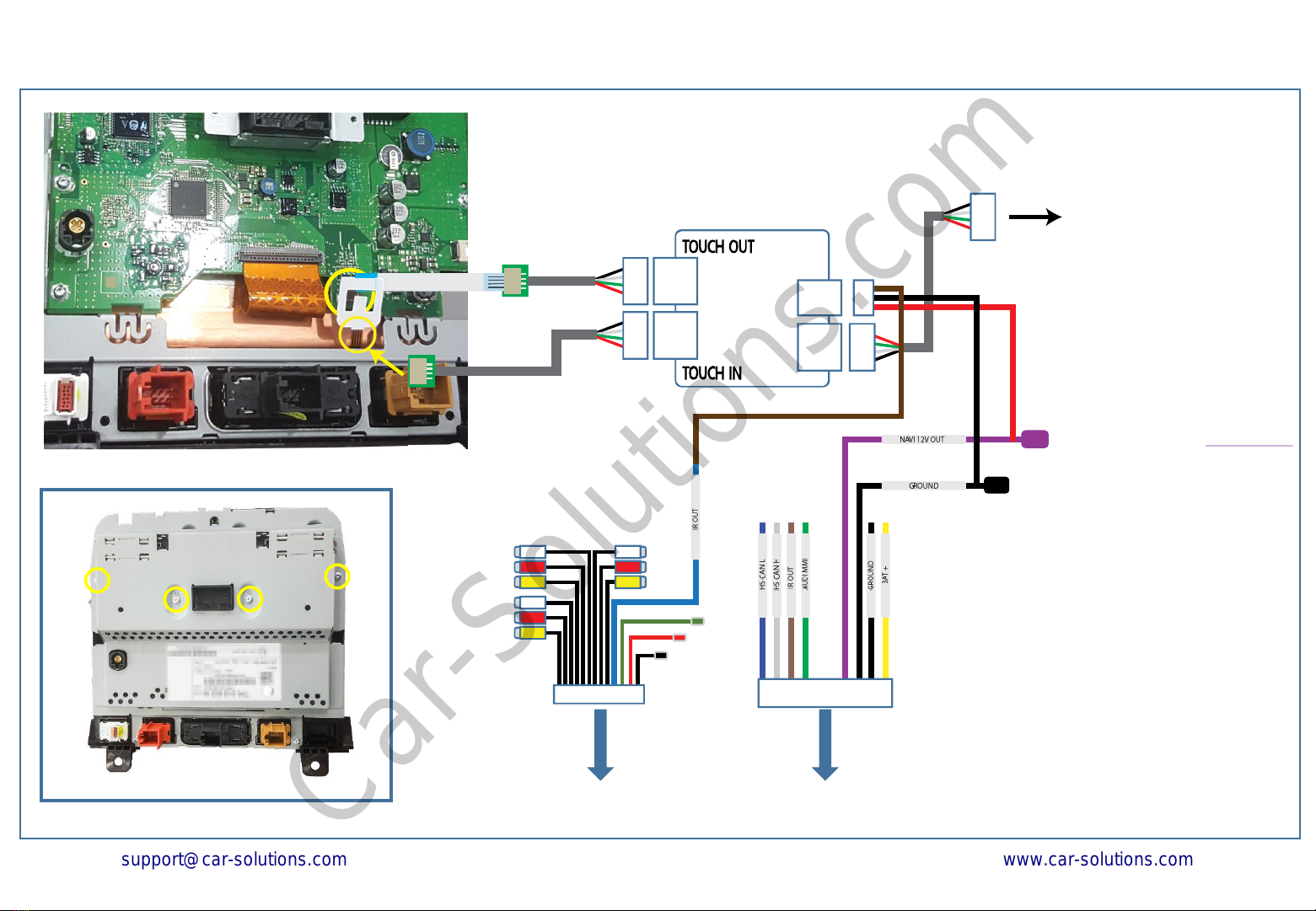
•Touch board Installation Diagram (Touareg)
•HDMI Connection Diagram
•Navigation Connection Diagram
•Compatibility Chart for Navigation(GPS) box models
•LVDS Connection Diagram
•Body Connector specifications
•Car Compatibility Chart
•Activation by original buttons of (Touareg)
•DIP Switch Settings
•Settings
1. Enter into the setting menu
2. HDMI mode settings
3. NAVI mode settings
4. Rear view camera settings
5. AV1(Front view camera) settings
6. Automatic activation function(AV1)
7. AV2 settings
8. System settings
9. System information
10. Information of Dip switch settings
_____________________________________________________________ 3
_________________________________________________ 4
_________________________________________ 5
______________________________________________ 6
____________________________ 7
____________________________________________ 8
_______________________________________ 9
___________________ 10
___________________________________________ 11
_______________________________________ 13
______________________________________________14
____________________________ 15
_________________________________________________ 16
_____________________________________ 17
___________________________________________ 18
____________________________________________ 18
_____________________________________ 19
________________________________ 19
______________________________ 20
___________________________________________________ 20
_______________________________________________ 21
____________________________________________ 21
______________________________ 22
Car-Solutions.com
www.car-solutions.com

3
IW04VW-T_related
•You should check the names and colors of each wires exactly, before you connect the wires.
ex) CAN HIGH: White wires / CAN LOW: Blue wires
• The ‘POWER / CAN Cable’ should always be connected last and be disconnected first.
•The 'Mode Switch' is an optional part to change modes forcibly without CAN-BUS.
Generally, the CAN-BUS wires are connected for changing modes by original buttons.
•When the reverse gear is not detected by CAN-BUS,
the 'REVERSE 12V IN wire’ should be spliced with 12V power of reverse light.
HDMI device_related
•HDMI mode accepts general-screen resolution of HDMI devices(1080P / 1920*1080).
If screen size of HDMI does not fit on the monitor, should adjust screen size & position in 'settings mode'.
•Generally, '5V 1A Power output(5V USB POWER)' is a standard voltage for charging smartphone.
If you need higher voltage than 5V, you should add a separate power supply.
Navigation(GPS) box_related
•When you connect the power wires(B+, ACC) to the navigation(GPS) box,
the ‘NAVI 12V OUT' wire supported by IW04VW-T should be spliced with anACC wire of navigation box.
•After installation is done, select an applicable navigation(GPS) box model in the 'Navigation model selection
menu' of setting mode.
•The navigation box should be powered off before unplugging the HDMI cable.
Cautions
Car-Solutions.com
www.car-solutions.com

Exterior
Dimension
4
ⓐ ⓑ ⓒ ⓓ ⓔ
ⓕ ⓖ ⓗ ⓘ ⓙ
ⓐDIP SWITCH
ⓑAV IN / OUT
ⓒTOUCH IN (Connect To Set top Device)
ⓓMODE
ⓔPOWER / CAN
ⓕHDMI IN
ⓖ5V USB POWER
ⓗNAVI IN
ⓘUART I/F
ⓙLVDS OUT
Width: 142 mm
Length: 91 mm
Height: 22 mm
Car-Solutions.com
www.car-solutions.com

Components
5
Optional Parts(sold separately at the indiwork)
Power / CAN Cable LVDS Cable LVDS PCB HDMI Cable AV IN / OUT Cable 5-pin Micro USB Cable
Mode Switch HDMI Extender
(For stick type HDMI device)
HDMI Cable
(Male to Male)
Touch board Components
PCB Power Touch Cable Touch In / Out Cable 4Pin FPC
Car-Solutions.com
www.car-solutions.com

RV-CAM Video Input
IR OUT
External Rear View
Camera
Audio(AUX) Output of
Navigation Box
Auxiliary(AUX)
Input of the car
External Front View
Camera
AV device
(ex: DTV Box, Divx) Navigation Box
DIP S/W Setting
LVDS
IN / OUT
PCB
Mode
Switch
(optional)
HDMI Device
HDMI
HDMI
HDMI
HDMI USB
FV-CAM Video Input
(AV1)
12V Power Output & GND Output(RV-CAM Power)
NAVI Audio Input
Audio Output
※Optional External Devices
AV-Input(AV2)
Reverse Signal Detection(optional)
Full Installation Diagram
LVDS IN / OUT Connection
Head Unit(OEM)
6
HDMI
HDMI USB
USB
AUDI MMI(Green)Pin # 10 = MMI DATA(Orange/Brown)
MMI DATA Pin Specification
Head Unit Original Main-Harness
1
4
5
8
9
10
12
13
15
16
Pin # 2 = CAN HIGH (Orange/Blue)
Pin # 3 = CAN LOW (Orange/Brown)
1 2 3
IR OUT
Pin # 12 = GND (Brown)
Pin # 15 = B+ POWER(Red)
TOUCH
BOARD
Touch board Installation Diagram
Please refer to next page
NAVI 12V Power Output (For Navigation)
GND Output
LS CAN wires
(Some vehicles should be connected the ‘LS CAN wires'.)
Power / CAN
Cable
HS CAN H(White)
HS CAN L(Blue)
* 20-Pin Connector of Climate controller
Car-Solutions.com
www.car-solutions.com

네비게이션용 12V 전원 출력
(NAVI 12V OUT)
내비게이션 전원 접지(GROUND)
순정 터치 필름과 연결
※ 폭스바겐 투아렉 모니터
모니터 PCB에 연결
※네비게이션
터치 케이블과 연결
TOUCH
BOARD
TOUCH BOARD Installation Diagram (TOUAREG)
Connect Interface Main Body
7
NAVI 12V Power Output (For Navigation)
GND Output
Connect
Navigation (GPS BOX) Touch in
※Touareg OEM Screen
Connect PCB
Connect FPC Cable
Car-Solutions.com
www.car-solutions.com

HDMI
HDMI
(Female)
USB
‘Stick Type’ HDMI Devices
HDMI IN 5V USB
POWER NAVI IN UART I/F LVDS OUT
HDMI Device
HDMI IN 5V USB
POWER NAVI IN UART I/F LVDS OUT
HDMI Device
USB
HDMI
HDMI
(Male)
‘Dongle & Adapter’ Type HDMI Devices
HDMI Connection Diagram
(5V-1A Power output for HDMI Device) (5V-1A Power output for HDMI Device)
8
(HDMI Extender) (HDMI Cable)
Car-Solutions.com
www.car-solutions.com

HDMI IN 5V USB
POWER NAVI IN UART I/F LVDS OUT HDMI IN 5V USB
POWER NAVI IN UART I/F LVDS OUT
HDMI
HDMI
9
Microcity - N-Link
USB
USB
iNAVI –X1 CUBE
HDMI
HDMI
TOUCH
BOARD
TOUCH
BOARD
Navigation Connection Diagram Navigation Connection Diagram
(USB cable connecting is for ‘N-Link’ only.)
Navigation(GPS) Box Navigation(GPS) Box
Car-Solutions.com
www.car-solutions.com

Model Country Dip S/W
(Navigation) Required Parts
MICROCITY
N-Link South Korea -
HDMI Cable USB A-A Cable
iNAVI
X1 CUBE South Korea
OFF(↑): 1, 2, 3, 4 HDMI Cable
MYVI
MS1400 Digital South Korea
OFF(↓): 1, 2, 3
ON(↑) : 4 HDMI Cable
Compatibility Chart for Navigation(GPS) box models
10
1 2 3 4
ON
↑
1 2 3 4
OFF
↓
ON
• The ‘IW04VW-T (HD-Link)' supports navigation(GPS) box models equipped with 'Digital video output'.
•It does not support the 'RGB video signals'.
Car-Solutions.com
www.car-solutions.com

HDMI
HDMI
Head Unit
HDMI IN 5V USB
POWER NAVI IN UART I/F LVDS OUT
LVDS
IN / OUT
PCB
LCD
Cable
11
•'Genuine(OEM) LVDS connector' should be connected
to 'LVDS IN / OUT PCB'.
• ‘Provided LVDS connector' should be connected to the
head unit instead to the genuine connector.
(OEM LVDS Cable)
(Provided LVDS Cable)
Monitor(OEM)
LVDS Connection
LVDS Connection Diagram
Car-Solutions.com
www.car-solutions.com

POWER / CAN MODE TOUCH-IN AV IN / OUT DIP SWITCH
12 3 4 5 6 7 8 9 10 11
12 13 14 15 16 17 18 19 20 21 22
1 BATTERY POWER INPUT
2 GND INPUT
3 GND OUTPUT
4 NAVI 12V POWER OUTPUT
5
6
7 AUDI MMI
8IR
9HS CAN HIGH
10 HS CAN LOW
1RV-CAM VIDEO INPUT 12 GND(RV-CAM VIDEO)
2RV-CAM POWER OUT 13 GND OUTPUT(RV-CAM)
3 REVERSE DETECTION 14 IR OUT
4 NAVI AUX INPUT R 15 GND(NAVI AUX IN R)
5 NAVI AUX INPUT L 16 GND(NAVI AUX IN L)
6 AUDIO OUTPUT R 17 GND(AUDIO OUT R)
7 AUDIO OUTPUT L 18 GND(AUDIO OUT L)
8 AV1 VIDEO INPUT 19 GND(AV1 VIDEO IN)
9 AV2 VIDEO INPUT 20 GND(AV2 VIDEO IN)
10 AV2 AUDIO INPUT R 21 GND(AV2 AUDIO IN R)
11 AV2 AUDIO INPUT L 22 GND(AV2 AUDIO IN L)
GROUND
IR OUT
REVERSE 12V IN
REAR 12V
REAR CAMERA
NAVI AUD IN R
NAVI AUD IN L
AUDIO OUT R
AUDIO OUT L
AV1 IN V
AV2 IN V
AV2 IN R
AV2 IN L
PUSH SWITCH TOUCH-IN
CABLE
•The colors of each wires can be changed under manufacturer’s circumstance.
Body Connector specifications
1 2
13
Length: 100 cm Length: 20 cm
Length: 150 cm Length: 150 cm
1 2 3 4
12 3 4 5 6 7 8 910
AUDI MMI
HS CAN H
HS CAN L
BAT +
GROUND
GROUND
NAVI 12V OUT
IR OUT
Car-Solutions.com
www.car-solutions.com

Car Models Production
Year Specific Models
Touareg 2010 ~ 7P5
IW04VW-T is used in combination with
Volkswagen Infotainment System.
The IW04VW-T supports the Volkswagen
Original screen equipped with ‘4 pin
LVDS round connector’ only.
Please check the specification of
original LVDS connector on the
sidelines of a production year.
14
Car Compatibility Chart
Car-Solutions.com
www.car-solutions.com

Activation by original buttons of Volkswagen
1
Button Function Operation Remarks
NAV
Changing
Modes Press the button 2 seconds. Order:
HDMI →NAVI →AV1 → AV2 →OEM
NAV
Shortcut to
each modes
Press the button 2 times consecutively. < OEM → NAVI >
Press the button 3 times consecutively. < OEM → AV1 >
Press the button 4 times consecutively. < OEM → AV2 >
NAV
System
Locking /
Unlocking Press the button 10 seconds long.
If you visit car service center, you can
lock the all functions of IW04VW-T.
It is only possible to use the OEM
functions under it is locked.
(Steering
Wheel
buttons)
Changing
mode to
Front View
Camera
mode(AV1)
Push the button left 2 seconds
long. It changes the screen from any
modes to AV1 mode directly.
CLIMATE
Reset to
factory
default
setting and
power.
Press the button 10 seconds long. You can use this function when you get in
trouble to see the screen while setting the
screen.
SETUP
Enter into the
setting menu Press the button 5 seconds long. Adjust settings of all functions like
adjustment screen size, brightness, and
etc.
1
1
Touareg
3
Volkswagen Touareg Monitor
2
4
1
23
15
Volkswagen Touareg Steering Wheel buttons
4
Car-Solutions.com
www.car-solutions.com

DIP Switch Settings
Pin
No. ON(▼)OFF(▲)
1HDMI Mode Skip HDMI Mode
2Navigation Mode Skip Navigation Mode
3External Rear View
Camera Original Rear View
Camera
4External Front View
Camera(AV1 Mode) Skip External Front View
Camera(AV1 Mode)
5AV2 Mode Skip AV2 Mode
6
Selection of car model
7
8
9
10
16
OFF
ON ON: ▼OFF:▲No.6 No.7 No.8 No.9 No.10 Car Models
OFF(▲) OFF(▲) OFF(▲) OFF(▲) OFF(▲)2010~ Touareg
(8inch Screen 800*480)
Car-Solutions.com
www.car-solutions.com

1
Button Function Operation
SETUP Enter into the
setting menu Press the button 5 seconds long.
CLIMATE(RETURN) Back to previous
menu Press the button short.
Selection Select the menu
and setting values. Press the button short.
Turn the dial
clockwise
Move the menu-
pointer and adjust
the setting values.
Move the pointer and setting
values to up(↑) and right(→).
Turn the dial
counterclockwise
Move the menu-
pointer and adjust
the setting values.
Move the pointer and setting
values to down(↓) and left(←).
3
1
4
2
3
45
5
17
2
1. Enter into the setting menu.
<Press the ‘SETUP’ button 5 seconds long.>
- HDMI & Navigation settings
- Rear view camera settings
-AV-input settings
- System settings
- System information
Settings
Car-Solutions.com
www.car-solutions.com

18
Settings
2. HDMI mode settings
- Mode selection: HDMI ↔ NAVI
- Image display
= Adjust the values of brightness and contrast
Red-Green-Blue colors of HDMI display.
- Screen position & size
= Adjust position and size of HDMI display.
3. NAVI mode settings
- Mode selection: NAVI ↔ HDMI
- Image display
= Adjust the values of brightness and contrast
Red-Green-Blue colors of NAVI display.
- Screen position & size
= Adjust position and size of NAVI display.
- Navigation model selection
①N-Link ②iNAVI –CUBE ③imercury –Class settop
④MYVI ⑤Mode A ⑥Mode B
Car-Solutions.com
www.car-solutions.com

19
Settings
4. Rear view camera settings
- Parking guide lines
= Adjust position of parking guide lines and
select the lines ‘ON or OFF’.
- Parking distance control
= Adjust position of parking distance control sensors
to ‘LEFT or RIGHT’ and select the PDC ‘ON or OFF’.
- Image display
= Adjust the values of brightness and contrast
Red-Green-Blue colors of Rear view camera display.
5. AV1(Front view camera) settings
- Mode selection:AV1(Front view camera) ↔ AV2
- Image display
= Adjust the values of brightness and contrast
Red-Green-Blue colors of AV1(Front view camera) display.
- Screen position & size
= Adjust the position and size of AV1 display.
- Automatic activation function(AV1)
= * Please refer to next page.
- Parking distance control
= Adjust the position of parking distance control sensors
to ‘LEFT or RIGHT’ and select the PDC ‘ON or OFF’.
Car-Solutions.com
www.car-solutions.com

20
6. Automatic activation function(AV1)
- Shift gear from reverse to drive
- Shift gear from parking to drive
* When you shift gear ‘from reverse to drive’ or ‘from parking to drive’,
it just works automatically during the activation time you selected.
7. AV2 settings
- Mode selection:AV2 ↔ AV1(Front view camera)
- Image display
= Adjust the values of brightness and contrast
Red-Green-Blue colors of AV2 display.
- Screen position & size
= Adjust the position and size of AV2 display.
Settings
Car-Solutions.com
www.car-solutions.com

21
Settings
8. System settings
- Safe mode
= Select the one of two between ‘ON and OFF’.
* If you select ‘ON’, 3 modes(HDMI, NAVI and AV2) will be faded out
when the car is driven.
- Factory default
= Reset all setting values to factory default setting.
9. System information
- Mode name: IW04VW-T
- Firmware date: 2015 -12 -21(Latest firmware date)
- = You can check the current firmware version date.
- Dip switch settings
= You can check the current positions of dip switch settings.
Car-Solutions.com
www.car-solutions.com
Table of contents