Version 27.08.2021 HW: CAM(V100)/(V20) RL4-MIB100
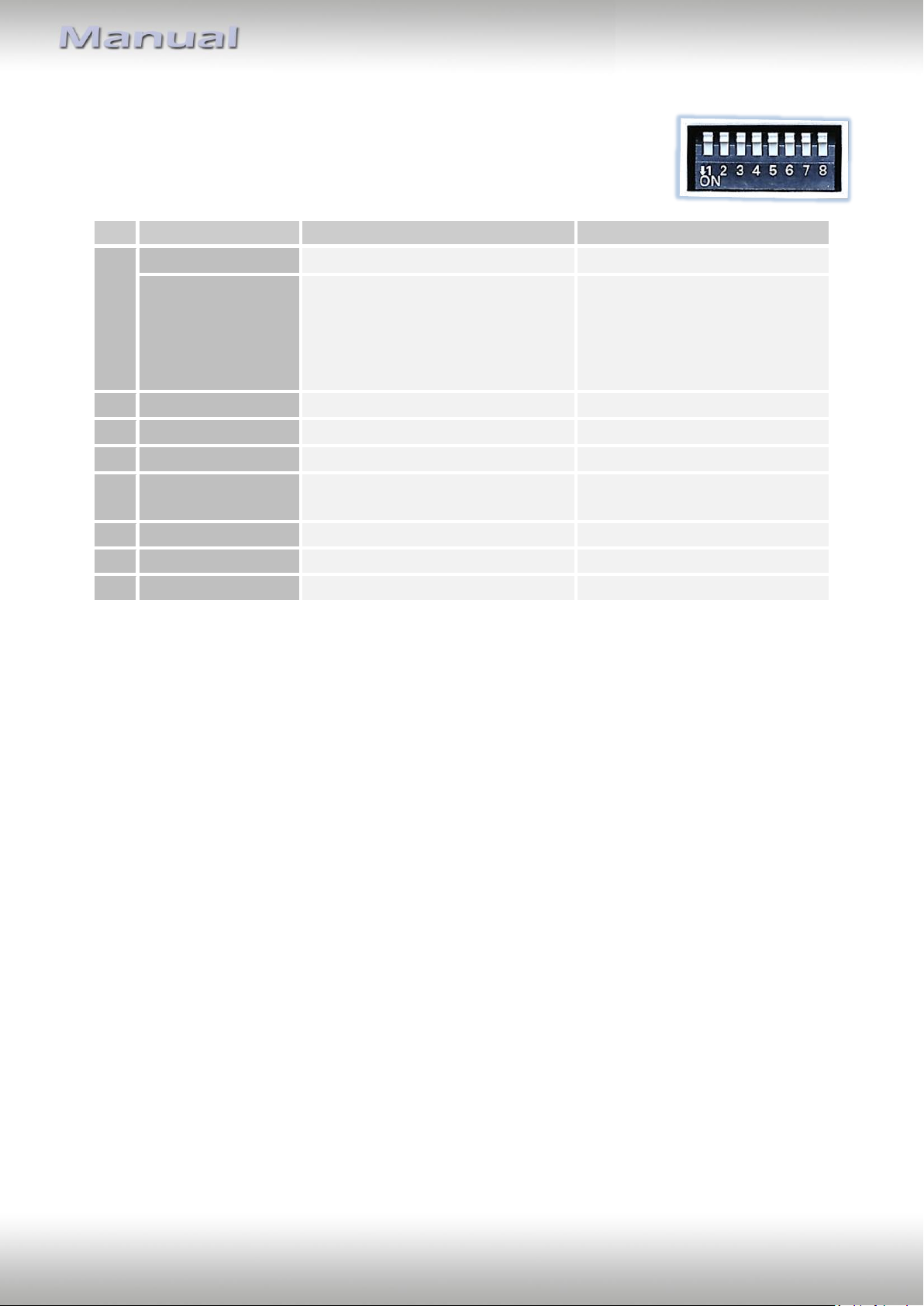
1.4.1. Activating the front camera (dip 1)
If set to ON, the interface switches for 10, 15 or 20 seconds from the rear-view camera to
the front camera input after having disengaged the reverse gear, depending on the menu
adjustments. In addition, a manual switch-over to the front camera input is possible via
keypad (short press) from any image mode.
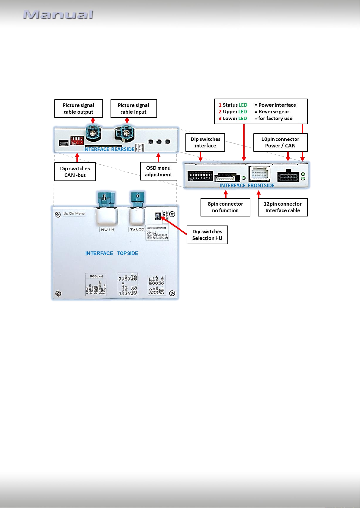
Description of the power supply output: see chapter “Power supply output”.
1.4.2. Enabling the interface’s video inputs (dip 2-3)
Only the enabled video inputs can be accessed by switching through the interface’s video
sources. It is recommended to enable only the required inputs. So the disabled inputs will be
skipped while switching through the video interfaces inputs.
1.4.3. Rear-view camera setting (dip 5)
If set to OFF, the interface switches to factory picture while the reverse gear is engaged to
display factory rear-view camera or factory optical park system picture.
If set to ON, the interface switches to its rear-view camera input while the reverse gear is
engaged.
1.4.4. Activating the guide lines (dip6)
If set to ON, the guide-lines will be shown on the display.
If set to OFF, the guide lines won’t be visible on the display.
Note: If there is no communication between interface and the vehicle`s CAN-bus (several
vehicles aren’t compatible), the reverse gear guide-lines can`t be shown during the vehicle’s
operation, even if they once appear after having switched the system to powerless!
1.4.5. Activation of the factory PDC display (Dip 7)
Dip 7 is used to switch between image formats of front and rear camera and to display the
factory PDC (if available) as „picture in picture“ in combination with the camera image.
For a detailed description, see chapter "Switching the Camera Image Formats and Factory
PDC Display ".
Dip switches 4 and 8 are out of function and have to be set to OFF.