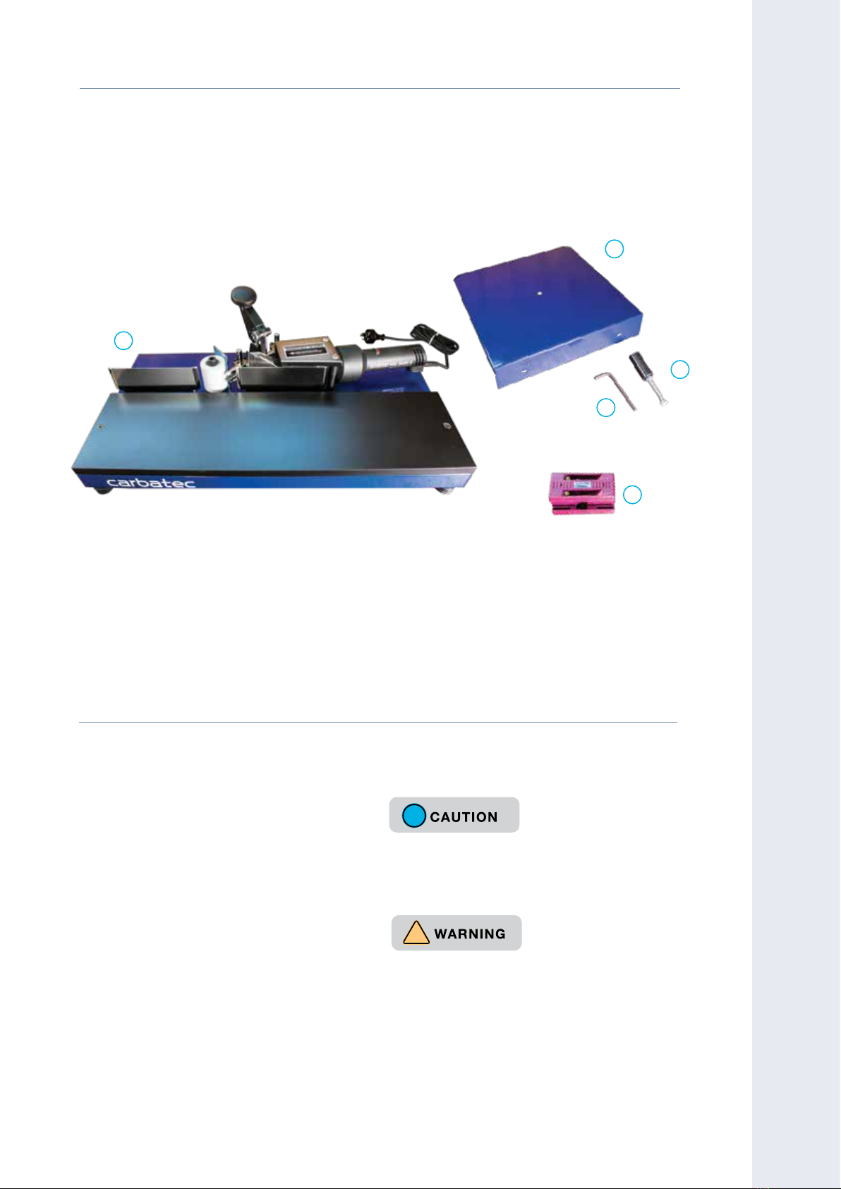
Carbatec EB-B2000P User manual

CARBATEC.COM.AU
EB-B2000P MANUAL
Benchtop Edgebander
2

FOR TECHNICAL SUPPORT CALL 1800 658 111
2
EB-B2000P
V1
Carbatec has been a trusted brand for woodworking enthusiasts
and professionals across Australia and New Zealand, since 1987.
Our quality woodworking products are designed and built to oer
value and performance, making the latest features and technological
advancements more accessible to Aussie woodworkers.
Backed by our no-fuss after-sales care and warranty support,
you can trust Carbatec to keep you woodworking, as promised.
We look forward to sharing in your woodworking journey!
If you have any questions about our products or service,
please call us on 1800 658 111 or email us at info@carbatec.com.au
Find us on social media
facebook.com/Carbatec
instagram.com/Carbatec
youtube.com/CarbaTecToolsForWood
THANK YOU
FOR CHOOSING

CARBATEC.COM.AU
3
EB-B2000P
!
DO NOT use acetone, gasoline or lacquer thinner
to remove any protective coatings.
If any parts are missing, do not attempt to plug in
the power cord and turn “ON” the machine. The
benchtop edgebander can only be turned “ON”
after all the parts have been installed correctly.
!
1. Remove parts from all of the cartons and
lay them on a clean work surface.
2. Remove any protective materials and
coatings from all of the parts and the
benchtop edgebander. The protective
coatings can be removed by spraying
WD-40 on them and wiping it o with a soft
cloth. This may need to be redone several
times before all of the protective coatings
are removed completely.
3. Compare the items above to verify that all
items are accounted for before discarding
the shipping box.
This benchtop edgebander will require a minimal amount of assembly.
A. Main unit with heat gun
B. Outrigger support table
C. Allen key
D. Support leg / Reel holder
E. Edge trimming tool
EB-B2000P BENCHTOP EDGEBANDER
The following items are provided in
the shipping box:
WHAT’S IN THE BOX
WELCOME
E
D
C
B
A

FOR TECHNICAL SUPPORT CALL 1800 658 111
4
EB-B2000P
CONTENTS
NOTE: The specifications, photographs, drawings and information in this manual represent
the current machine model when the manual was prepared. Changes and improvements
may be made at any time, with no obligation on the part of Carbatec to modify previously
delivered units. Reasonable care has been taken to ensure that the information in this
manual is correct, to provide you with the guidelines for the proper safety, assembly and
operation of this machine.
Introduction 2
What’s in the box 3
Contents 4
Overview 5
Specications 6
Safety instructions - General 7–10
Safety instructions - Edgebander 11
Safety instructions - Electrical 12
Assembly 13–14
Operation 15–16
Maintenance & Troubleshooting 17
Parts diagram 18
Warranty 19

CARBATEC.COM.AU
5
EB-B2000P
K
I
H
G
F
E
D
C
B
A
A. Table
B. Outfeed fence
C. Roller
D. Banding guides
E. Band cutter
F. Infeed fence
G. Outrigger support table
H. Edgebanding roll pin
I. Heat gun
J. ON/OFF switch
K. Temperature control
L. Edge trimming tool
BENCHTOP EDGEBANDER OVERVIEW
OVERVIEW
OVERVIEW
J
L

FOR TECHNICAL SUPPORT CALL 1800 658 111
6
EB-B2000P
CODE EB-B2000P
BRAND Carbatec
POWER 2000 W
OVERALL SIZE (W x Ø)680 x 680 mm
WEIGHT 13 kg
SPECIFICATIONS
The Carbatec benchtop edgebander has been designed to handle wood and polyester
edgebanding materials. All edgebanding materials used with this machine must be backed
with a hot melt adhesive. The heat gun prepares the glue for bonding to the substrate.
The benchtop edgebander will accommodate material as wide as 56 mm. The upper and
lower edge band guides are adjustable to t dierent widths of material.
The width of the edgebanding material you select is dependent on the thickness of the
stock you are edgebanding. The edgebanding material is usually more than 1.6 mm wider
than the stock. This gives you 0.8 mm of excess to remove from either side of the work with
the double edge laminate trimmer supplied.
DATE OF PURCHASE:
SERIAL NUMBER:
Record the serial number and date of purchase
in your manual for future reference.
2
Model:
Voltage
Freq:
Phase:T
Amp:
kW:
Speed:
Lot No.:
Serial No.:
Date:
QUALITY INSPECTED
Key information can be found on the inspection panel, found on the rear of the machine.

CARBATEC.COM.AU
7
EB-B2000P
Carbatec products bearing the Regulatory Compliance Mark (RCM) have been
tested in accordance with applicable Australian/New Zealand Standards
to ensure their compliance with all mandatory standards and regulations
(applicable at time of original sale). Carbatec Pty Ltd are registered as a
responsible supplier with relevant Australian government departments and
our products are registered on the EESS & ACMA database.
!
!
!
!A safety alert symbol Indicates DANGER, WARNING, or CAUTION.
May be used in conjunction with other symbols or pictographs.
Indicates an imminently hazardous situation, which, if not avoided,
will result in death or serious injury.
Indicates a potentially hazardous situation, which, if not avoided,
could result in death or serious injury.
Indicates a potentially hazardous situation, which, if not avoided,
could result in minor or moderate injury.
(Without Safety Alert Symbol) Indicates a situation that may result
in property damage.
SYMBOL MEANING
Be sure to read and understand all safety instructions in this manual, including all safety
alert symbols such as “DANGER,” “WARNING,” and “CAUTION” before using this tool.
Failure to following all instructions listed below may result in electric shock, re, and/or
serious personal injury.
!
IMPORTANT! Safety is the single most important consideration in the operation of this
equipment. The following instructions must be followed at all times. Failure to follow all
instructions listed below may result in electric shock, re, and/or serious personal injury.
There are certain applications for which this tool was designed. We strongly recommend
that this tool not be modied and/or used for any other application other than that for
which it was designed. If you have any questions about its application, do not use the tool
until you have contacted us and we have advised you.
The purpose of safety symbols is to attract your attention to possible dangers. The safety
symbols and the explanations with them deserve your careful attention and understanding.
The symbol warnings do not, by themselves, eliminate any danger. The instructions and
warnings they give are no substitutes for proper accident prevention measures.
SAFETY INSTRUCTIONS
SAFETY

FOR TECHNICAL SUPPORT CALL 1800 658 111
8
EB-B2000P
!
!
Operating a power tool can be dangerous if
safety and common sense are ignored. The
operator must be familiar with the operation of
this machine. Read this manual to understand this
machine. DO NOT OPERATE this machine IF YOU
DO NOT FULLY UNDERSTAND the limitations of
this tool. DO NOT MODIFY this machine in any way.
BEFORE USING
THIS MACHINE
To avoid serious injury and damage to the tool,
read and follow all of the Safety and Operating
Instructions before operating the machine.
1. SOME DUST CREATED BY USING
POWER TOOLS CONTAINS CHEMICALS
known to cause cancer, birth defects, or
other reproductive harm. Some examples of
these chemicals are:
• Lead from lead-based paints.
• Crystalline silica from bricks, cement, and
other masonry products.
• Arsenic and chromium from chemically
treated lumber
Your risk from these exposures varies,
depending on how often you do this type
of work. To reduce your exposure to these
chemicals: work in a well ventilated area
and work with approved safety equipment,
such as those dust masks that are specially
designed to lter out microscopic particles.
GENERAL SAFETY
2. READ this entire manual. LEARN how to use
the tool for its intended applications.
3. GROUND ALL TOOLS. If the tool is supplied
with a 3-prong plug, it must be plugged into
a 3-contact electrical receptacle. The third
prong is used to ground the tool and provide
protection against accidental electric shock.
4. AVOID A DANGEROUS WORKING
ENVIRONMENT. Do not use electrical tools in
a damp environment or expose them to rain.
5. DO NOT USE electrical tools in the presence
of FLAMMABLE liquids or gases.
6. ALWAYS KEEP THE AREA CLEAN, well lit,
and organized. Do not work in an environment
with oor surfaces that are slippery from
debris, grease, and wax.
7. KEEP VISITORS AND CHILDREN AWAY. Do
not permit people to be in the immediate
work area, especially when the electrical tool
is operating.
8. DO NOT FORCE THE TOOL to perform an
operation for which it was not designed. It
will do a safer and higher quality job by only
performing operations for which the tool was
intended.
9. WEAR PROPER CLOTHING.
Do not wear loose clothing, gloves, neckties,
or jewellery. These items can get caught in
the machine during operations and pull the
operator into the moving parts. The user
must wear a protective cover on their hair, if
hair is long, to prevent it from contacting any
moving parts.

CARBATEC.COM.AU
9
EB-B2000P
19. MAINTAIN YOUR BALANCE. Do not extend
yourself over the tool. Wear oil resistant
rubber soled shoes. Keep oor clear of
debris, grease, and wax.
20. MAINTAIN TOOLS WITH CARE. Always
keep tools clean and in good working order.
Keep all blades and tool bits sharp, dress
grinding wheels and change other abrasive
accessories when worn.
21. EACH AND EVERY TIME, CHECK FOR
DAMAGED PARTS PRIOR TO USING THE
TOOL. Carefully check all guards to see that
they operate properly, are not damaged, and
perform their intended functions. Check for
alignment, binding or breaking of moving
parts. A guard or other part that is damaged
should be immediately repaired or replaced.
22. DO NOT OPERATE TOOL WHILE TIRED,
OR UNDER THE INFLUENCE OF DRUGS,
MEDICATION OR ALCOHOL.
23. SECURE ALL WORK. Use clamps or jigs to
secure the work piece. This is safer than
attempting to hold the work piece with
your hands.
24. STAY ALERT, WATCH WHAT YOU ARE
DOING, AND USE COMMON SENSE WHEN
OPERATING A POWER TOOL. A moment of
inattention while operating power tools may
result in serious personal injury.
25. ALWAYS WEAR A DUST MASK TO PREVENT
INHALING DANGEROUS DUST OR
AIRBORNE PARTICLES, including wood dust,
crystalline silica dust and asbestos dust.
Direct particles away from face and body.
10. CHILDPROOF THE WORKSHOP AREA by
removing switch keys, unplugging tools from
the electrical receptacles, and using padlocks.
11. ALWAYS UNPLUG THE TOOL FROM THE
ELECTRICAL RECEPTACLE
when making adjustments, changing parts or
performing any maintenance.
12. KEEP PROTECTIVE GUARDS IN PLACE AND
IN WORKING ORDER.
13. AVOID ACCIDENTAL STARTING. Make sure
that the power switch is in the “OFF” position
before plugging in the power cord to the
electrical receptacle.
14. REMOVE ALL MAINTENANCE TOOLS from
the immediate area prior to turning “ON”
the machine.
15. USE ONLY RECOMMENDED ACCESSORIES.
Use of incorrect or improper accessories
could cause serious injury to the operator
and cause damage to the tool. If in doubt,
check the instruction manual that comes with
that particular accessory.
16. NEVER LEAVE A RUNNING TOOL
UNATTENDED. Turn the power switch to the
“OFF” position. Do not leave the tool until it
has come to a complete stop.
17. DO NOT STAND ON A TOOL. Serious injury
could result if the tool tips over, or you
accidentally contact the tool.
18. DO NOT STORE ANYTHING ABOVE OR
NEAR the tool where anyone might try to
stand on the tool to reach it.
SAFETY

FOR TECHNICAL SUPPORT CALL 1800 658 111
10
EB-B2000P
26. USE A PROPER EXTENSION CORD IN GOOD
CONDITION. Use of extension cords should
be avoided where possible. When using an
extension cord, be sure to have a cord heavy
enough to carry the current your product will
draw, and with compatible pin conguration
and connections (NEVER use an extension
cord rated at less than your machine).
Longer run extensions will need heavier
duty extension cords. Only connect your
extension cord or machine to a receptacle
that accepts your plug and never modify your
plug to suit a receptacle.
Always operate tool in well ventilated area
and provide for proper dust removal. Use
dust collection system wherever possible.
Exposure to dust may cause serious and
permanent respiratory or other injury,
including silicosis (a serious lung disease),
cancer, and death. Avoid breathing dust, and
avoid prolonged contact with dust. Allowing
dust to get into your mouth or eyes, or lay on
your skin may promote absorption of harmful
material. Always use properly tting AS/NZS
approved respiratory protection appropriate
for the dust exposure, and wash exposed
areas with soap and water.
NOTE: According to the applicable product liability law the manufacturer of this
device is not liable for damages which arise on or in connection with this device in
case of:
• Improper handling
• Non-compliance with the instructions for use
• Repairs by third party, non authorised skilled workers
• Installation and replacement of non-genuine spare parts
• Improper use
RECOMMENDATIONS:
• Read the entire text of the operating instructions prior to the assembly
and operation of the device. These operating instructions are intended to
make it easier for you to get familiar with your device and utilise its intended
possibilities of use.
• The operating instructions contain important notes on how to work safely
with your machine and how to avoid dangers, and increase the reliability and
working life of the machine.
• Retain and store these instructions near the machine. The instructions must be
read and carefully observed by each operator prior to starting the work.
• In addition to the safety notes contained in the present operating instructions
and the special regulations of your country, the generally recognised technical
rules for the operation of wood working machines must be observed.
GENERAL SAFETY

CARBATEC.COM.AU
11
EB-B2000P
EDGEBANDER SAFETY
The device and packaging materials are not toys! Children must not be
allowed to play with plastic bags, lm and small parts! There is a risk of
swallowing and suocation!
INTENDED USE
• The machine must only be used in technically perfect condition in
accordance with its designated use and the instructions set out in the
operating manual, and only by safety-conscious persons who are fully
aware of the risks involved in operating the machine. Any functional
disorders, especially those aecting the safety of the machine, should
therefore be rectied immediately. The safety, work and maintenance
instructions of the manufacturer as well as the technical data given in
the calibrations and dimensions must be adhered to.
• Relevant accident prevention regulations and other, generally
recognised safety-technical rules must also be adhered to.
• The machine may only be used, maintained, and operated by persons
familiar with it and instructed in its operation and procedures.
Arbitrary alterations to the machine release the manufacturer from all
responsibility for any resulting damages.
• The machine may only be used with original accessories and tools
made by or recommended by the manufacturer.
• Any other use exceeds authorisation. The manufacturer is not
responsible for any damages resulting from unauthorised use; risk is
the sole responsibility of the operator.
SAFETY FOR BENCHTOP EDGEBANDER
• This benchtop edgebander is intended for use in dry conditions, and for
indoor use only.
• Do not put your hand or any part of your body directly in front of the
nozzle of the heat gun.
• Keep all combustible materials away from this tool.
SAFETY

FOR TECHNICAL SUPPORT CALL 1800 658 111
12
EB-B2000P
FIG. BFIG. A
!
This tool must be grounded while in use to
protect the operator from electric shock. IN THE
EVENT OF A MALFUNCTION OR BREAKDOWN,
grounding provides the path of least resistance
for electric current and reduces the risk of electric
shock. This tool may be equipped with an electric
cord that has an equipment grounding conductor
and a grounding plug. The plug MUST Be plugged
into a matching electrical receptacle that is
properly installed and grounded in accordance
with ALL local codes and ordinances.
DO NOT MODIFY THE PLUG PROVIDED.
If it will not t the electrical receptacle, have the
proper electrical receptacle installed by a qualied
electrician.
IMPROPER ELECTRICAL CONNECTION of the
equipment grounding conductor can result in
risk of electric shock. The conductor with the
green insulation (with or without yellow stripes)
is the equipment grounding conductor. DO NOT
connect the equipment grounding conductor to a
live terminal if repair or replacement of the electric
cord or plug is necessary.
CHECK WITH A QUALIFIED ELECTRICIAN
or service personnel if you do not completely
understand the grounding instructions, or if you
are not sure the tool is properly grounded.
Use only a 3-wire extension cord that has a
3-prong grounding plug and a 3-pole receptacle
that accepts the tool’s plug. Replace a damaged
or worn cord immediately.
Power tools and machinery are intended for use
on a circuit that has an electrical receptacle as
shown in FIGURE A that shows a 10 Amp 3-wire
electrical plug and corresponding electrical
receptacle that has a grounding conductor.
If this particular tool has been designed and tted
with a two prong electrical plug, ensure it displays
the ‘Double Insulated’ logo shown in FIGURE B,
before connecting to a 3- wire receptacle.
Never modify the standard tted electrical
plugs to t your receptacle.
!
ELECTRICAL SAFETY

CARBATEC.COM.AU
13
EB-B2000P
Fig. A1A. BODY SETUP
1. Assemble the outrigger support table
that houses the roll of banding to the
main body of the edgebander using the
two M6 socket head cap screws and
washers supplied.
Fig. A1 & A2
NOTE: The socket head cap screws and washers
are inserted into the holes on rear of main unit.
Remove them prior to continuing.
2. Take the M8x100 hex cap screw and
put it through the hole in the centre of
the support table and screw it into the
bottom of the pin. Make sure the hex
nut is on the bottom side of the table
in order to lock the screw in place. The
height of the screw should be level
with the feet of the main body of the
machine.
Fig. A3, A4 & A5
ASSEMBLY
Fig. A1
ASSEMBLY
Fig. A1
Fig. A2
Fig. A1
Fig. A3
Fig. A1Fig. A4
Fig. A1Fig. A5

FOR TECHNICAL SUPPORT CALL 1800 658 111
14
EB-B2000P
B. BANDING GUIDE
ADJUSTMENT
1. Loosen the socket head cap screws to
adjust the upper and lower edge guides.
Fig. B1
NOTE: The lower guides are best set just below
the table.
2. To adjust the guides to t dierent
widths of banding, use the top guides
for adjustment. Do not make the t too
tight, you need the banding to slide
easily through the guides
Fig. B2 & B3
C. FENCES ADJUSTMENT
The infeed and outfeed fences have been factory
set although you may want to check the setup is
suitable for your chosen edgebanding material. Both
fences should be set slightly back from the roller, by
approximately the thickness of your edgebanding
material. This will ensure eective pressure against
roller, and along the outfeed fence, and better
adhesion of the edgebanding material.
1. Place a straight edge or rule across both
infeed and outfeed fences.
Fig. C1
2. Check the alignment of the fences for
parallel, and for the position of the roller,
in relation to the fences.
3. Adjust the outfeed fence as required
by loosening the two cap screws on
the rear of the fence, adjusting and re-
tightening into position.
4. Adjust the infeed fence as required
ASSEMBLY
Fig. B1
Fig. B2
Fig. B3
Fig. C2 GUN REMOVED
GAP
SOCKET HEAD
CAP SCREWS
Fig. C1
GAP

CARBATEC.COM.AU
15
EB-B2000P
!
The nozzle of the heat gun and the air from it are
VERY HOT. Do not put hands anywhere near the
nozzle. Keep away from combustible material!
OPERATION
D. HEAT GUN CONTROLS
The ON/OFF switch is at the end of the handle.
The dial adjusts the intensity of the heat. Red is
hotter, blue is cooler.
Fig. D1
E. FEEDING THE
EDGEBANDING
1. Position the edgebanding roll over
the pin on the outrigger support table.
Feed the banding through the edge
guides with the glued surface facing out
towards the nozzle of the gun.
2. Position the end of the edgebanding
in front of the heat gun and turn it on.
It takes up to 30 seconds for the glue
to melt. It will start to bubble when it is
hot enough to start feeding. As the glue
softens, hand feed the banding onto the
roller.
3. Place the workpiece on the table and
against infeed fence. Feed it towards
the roller until the banding is caught
between the roller and the workpiece.
Keep feeding steadily, putting some
OPERATION
Fig. D1
Fig. E1
by rst switching OFF the heat gun,
removing it from power and allowing it to
cool completely.
5. Once cool, loosen the two top screws
that retain the heat gun in the saddle.
Note its position or mark the heat gun
body with a pen.
6. Adjust the infeed fence as required by
loosening the two cap screws on the
rear of the fence, adjusting and re-
tightening into position.
7. Re-t the heat gun ensuring it is placed
in the same position.
8. Depending on your edge band material,
only minor adjustment may be needed
to the outfeed fence.

FOR TECHNICAL SUPPORT CALL 1800 658 111
16
EB-B2000P
pressure against the roller to ensure the
glue adheres to the surface of the board.
Fig. E1
NOTE: The hotter the gun, the faster the feed
rate. We advise doing a sample rst, to establish
correct feed rate and heat. If the air is too cool
or the feed rate is too quick, there will not be
sucient bond.
4. When the end of the board is
approximately 40 mm from the end
of the infeed fence, press the veneer
cutting knob.
Fig. E2
5. Continue edgebanding until the entire
edge of the work is covered. The
veneer will extend slightly beyond the
workpiece.
6. Turn o the gun and unplug it from the
power source. Allow it to cool completely
before storing your edge bander.
F. TRIMMING THE
EDGEBANDING
Your edgebander is supplied with a double edge
trimmer. It will trim materials from 12.7 to 25 mm
thick.
1. Trim excess length with a sharp knife.
2. Place the edge trimmer over the edge of
the board.
3. Squeeze together and slide down
the board.
Fig. F1
NOTE: Optional End Trimmer is also available.
OPERATION
Fig. F1
Fig. F2
Fig. E2

CARBATEC.COM.AU
17
EB-B2000P
G. MAINTENANCE
Prolonged use of the edgebander may cause a
buildup of adhesive on the banding guides that
can be removed.
1. Turn the heat gun on at a medium setting.
MAINTENANCE
TROUBLESHOOTING
TO PREVENT INJURY TO YOURSELF or damage to the machine, turn the switch to the
“OFF” position and unplug the power cord from the electrical receptacle before making any
adjustments.
PROBLEM LIKELY CAUSE(S) SOLUTION(S)
Edgebander will
not turn on.
1. Not connected to power source.
2. Fuse blown, or circuit breaker
tripped.
3. Cord damaged.
4. Hot air gun motor damaged.
1. Check plug connection.
2. Replace fuse, or reset circuit breaker.
3. Replace cord.
4. Have hot air gun repaired or
replaced.
Edgebander will
not heat.
1. Temperature dial not set properly.
2. Hot air gun motor damaged.
1. Turn temperature dial toward the
red .
2. Have hot air gun repaired or
replaced.
Edgebanding
material does not
feed smoothly
through guides.
1. Guides not adjusted properly.
2. Guides need cleaning.
1. Position guides according to width
of edgebanding material.
2. Follow instructions for cleaning o
old adhesive from guides.
Edgebanding
material will not
bond to workpiece.
1. Hot air gun not hot enough.
2. Feed rate too fast for heat level.
3. Infeed and/or outfeed fence not set
properly
4. Edgebanding material does not
have hot melt backing, or has poor
adhesive, or is defective.
1. Turn temperature dial toward the red
to increase heat.
2. Reduce feed rate, or increase heat
level.
3. Fences should be recessed 1/32" to
3/64" from crown of pinch roller.
4. Replace edgebanding material.
Edgebanding
material is dicult
to cut.
1. Plunge cutter being pushed down
too lightly or slowly.
2. Knives in plunge cutter unit are dull.
1. Push down plunge cutter rapidly and
rmly.
2. Replace knives in plunge cutter unit.
MAINTENANCE & TROUBLESHOOTING
2. As the adhesive softens, peel if o with
a putty knife. Be careful not to scratch
the surface of the guides as this might
hinder a smooth feed rate.

FOR TECHNICAL SUPPORT CALL 1800 658 111
18
EB-B2000P
PART
REF.
QTY
DESCRIPTION PART
REF.
QTY DESCRIPTION PART
REF.
QTY DESCRIPTION
11OUTRIGGER SUPPORT 17 1BOTTOM RETAINING CLAMP 33 1HEAT SHIELD
21STUD 18 1NOZZLE (070236) 34 7EYELET WASHER (M6x13)
316 HEX SCREW (M6 1.0x10) 19 1HOT AIR GUN 35 1STUD
47EYELET WASHER (M6x20) 20 1ELECTRIC CORD 36 2LOWER EDGE GUIDE
52UPPER EDGE GUIDE 21 2FLAT HEAD SCREW (M6 1.0x20) 37 1CAP SCREW (M8 1.25x90)
61PINCH ROLLER 22 1WORK TABLE 38 1HEX NUT (M8 1.25)
72BALL BEARING(6200#1) 23 4RUBBER BOOT 39 1HEX SCREW (M6 1.0x14)
81HEX SCREW (M10 1.5x80) 24 5HEX SCREW (M6 1.0x16) 40 1HEX NUT(M10 1.5)
93TAPPING SCREW (M4x12) 25 1BASE 41 1SPACER
10 1HANDLE (RIGHT) 26 1FENCE 42 1KNIFE GUARD (RIGHT)
11 1HANDLE (LEFT) 27 2TAPPING SCREW (M5x15) 43 1KNIFE BASE
12 2HEX NUT (M6 1.0) 28 4EYELET WASHER (M8x23) 44 1HEX SCREW (M6 1.0x35)
13 2RETAINING SCREW 29 1HEX NUT (M8 1.25) 45 1SPRING
14 2EYELET WASHER (M5x15) 30 1HEX NUT (M10 1.5) 46 1UPPER KNIFE
15 1HEAT SHIELD 31 5HEX NUT (M6 1.0) 47 1KNIFE GUARD (LEFT)
16 1TOP RETAINING CLAMP 32 1FENCE 48 1BOTTOM KNIFE
36
35
3
34
33
4
32
31
23
24
30
29
25
23
22
21
18
19
15
16
17
12
31
48
34
47
14
13
26
20
24
27
28
3
38
37
1 2 4 5 6 7 8 9 10 11 123
42
43
44 3
3
4
45
46
34
28
40
41
439
PARTS DIAGRAM

CARBATEC.COM.AU
19
EB-B2000P
2 YEAR WARRANTY
WARRANTY
A. We warrant that this Carbatec product will be free
from defects caused by faulty workmanship or faulty
materials for a period of 2 years from date of sale.
B. This warranty is in addition to other rights and
remedies you may have under a law in relation to the
goods.
C. This warranty does not apply in any of the following
cases:
i. Defects arising from:
1. fair wear and tear;
2. corrosive atmosphere;
3. damage or injury caused by deliberate act,
lack of care or failure to comply with the
recommended care and maintenance for the
goods;
4. improper use of the goods;
5. alterations or repairs
(not made by us) to the goods;
ii. defects arising from an event outside of our
control such as re, ood, earthquake or other
natural calamity, motor vehicle or other accident,
strike, civil unrest, terrorism or war;
iii. to accessory items such as after-market jigs,
accessories or other items which are not sold or
serviced by us and which are not sold with or were
not included with the main unit purchased; or
iv. to wearable parts such as drive belts/shafts,
bearings, bandsaw tyres, motor brushes, blades or
abrasive belts/discs or other cutting or machining
implements.
v. damage caused to any electrical component,
where connected to a power supply outside
the country for which it was designed (namely
Australia or New Zealand).
D. If this warranty applies and you have complied with
the procedure below for making a claim, we will,
at our election, either repair the goods (or those
parts of the goods recognised as defective) or will
provide a replacement within a reasonable time at our
expense.
E. If this warranty applies, the procedure for
making a claim is:
i. you must contact us by email;
ii. you must include in the email the following
information:
1. a copy of the order or receipt for the goods;
2. the serial or batch number printed on the
machinery manufacturing plate; and
3. a detailed description of the fault and how and
when it arose; and
4. If the fault is a type covered by this warranty,
we will then make arrangements with you for
the return of the goods to us (for repair or
replacement) at our cost using our transport
providers or we may decide to attend at your
premises to repair or replace the goods.
F. Our liability (and that of our resellers) under this
warranty is wholly limited to repair or replacement of
the goods (or those parts of the goods recognised as
defective) in accordance with the procedure above
and you have no right to other compensation, costs
or damages under this warranty. But this does not
mean that you may not have other rights under a law
in relation to the goods.
G. If following our inspection of goods returned by you
under this warranty it is found that this warranty
does not apply and you are not otherwise entitled to
repair or replacement by us, you must, if requested
by us, reimburse our costs including parts, labour and
freight.
H. This warranty is not transferable and only the person
who purchased the goods may make a claim.
Where the goods have been exported outside Australia
or New Zealand, the Company may not require the
Purchaser to return any allegedly faulty or defective
Product for evaluation. However, the Company has the
right to request the return for evaluation at purchasers
cost.
STATUTORY NOTICE
Our goods come with guarantees that cannot be
excluded under the Australian Consumer Law. You are
entitled to a replacement or refund for a major failure and
for compensation for any other reasonably foreseeable
loss or damage. You are also entitled to have the goods
repaired or replaced if the goods fail to be of acceptable
quality and the failure does not amount to a major failure.
PARTS DIAGRAM & WARRANTY

2
CARBATEC.COM.AU
Carbatec Pty Ltd
E inf[email protected]om.au
AU 1800 658 111
NZ 0800 444 329
128 Ingleston Road, Wakerley,
Queensland Australia 4154
ABN 84 010 706 242
Table of contents
Other Carbatec Industrial Equipment manuals
Popular Industrial Equipment manuals by other brands

AUTOMEC
AUTOMEC CoastOne Original user manual

WIKA
WIKA TW61 operating instructions

Jäger
Jäger KS2-06/80-2 manual

Riello
Riello MODULO 32 MIX instruction manual

Alemite
Alemite Carbon Shield CS-5700 Series Installation, operation and maintenance manual

Siemens
Siemens 3KC3424-2AA22-0AA3 operating instructions