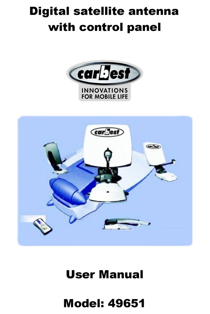
Carbest Multi-Sat X65 User manual

Multi-Sat X65 / X85 / X85 Twin
X65 (49631) / X85 (49632) / X85 Twin (49633)
EN - INSTRUCTION MANUAL
DE - BEDIENUNGSANLEITUNG
FR - MANUEL DE L´UTILISATEUR
NL - HANDLEIDING
49631_32_33_Cover_User_Manual_148x210.indd 3 05.10.18 11:55


1. General Information
.............................................................................................
...............................................................................
.............................................................................................
1-1. Introduction
1-2. Proper use and operation
1-3. Safety notes
2
2
3
2. Contents
...................................................................................
...........................................................................................
2-1. Components bundle
2-2. Name of parts
4
5
10. Caravan/Motorhome installation
..........................................................
.............................................................................
.............................................................................
10-1. Required space for the CARBEST Multi-Sat antenna
10-2. Equipment for installation
10-3. Instruction for installation
21
23
23
6. Functional description
.........................................................................................
..................................................................................
.......................................................................................
...........................................................................
......................................................................................
6-1. Get ready to use
6-2. Searching the satellite
6-3. DiSEqC 1.1 setting
6-4. STB power detection On/O
6-5. Power save mode
14
15
15
16
16
7. Extra functions
9. Specications
...........................................................................................
............................................................................................
.......................................................................................
.......................................................................
7-1. Error message
7-2. Factory reset
7-3. Software upgrade
7-4. Manual satellite update function
17
17
17
18
...............................................................................................
............................................................................................
9-1. Dimension
9-2. Specications
20
20
8.Trouble shooting ................................................................................ 19
3. How to assemble
4. Connection diagram
5. Skew adjustment
................................................................................
...........................................................................
.................................................................................
6
11
12
Contents

ENGLISH - 2
•
•
•
•
•
•
•
1. General Information
1-1. Introduction
These instructions describe the functions and operation of the CARBEST Multi-Sat
antenna.
Correct and safe operation of the system can only be ensured by following these
instructions.
Your CARBEST Multi-Sat antenna is an intelligent satellite TV reception antenna
system which can align itself towards a preset satellite automatically as long as the
system is located within the footprint of the selected satellite.
For general operation, please ensure that the system always has a clear view to the sky.
If the satellite‘s signal beam is interrupted by obstacles such as mountains, buildings or
trees, the unit will not function and no TV signal will be received.
1-2. Proper use and operation
This product has been designed for fixed installation on vehicles with maximum speeds
of 130 km/h. It is designed to automatically aim an antenna at geostationary television
satellites. The power to the system is supplied by a standard vehicle electrical system
with a rated voltage of 12 Volts DC.
Use of the equipment for any other purpose to the one specified is not permitted.
Please also note the following instructions from the manufacturer :
It is not permitted to change the overall device by removing or adding individual
components.
The use of any other parabolic reectors or LNBs to those originally
installed is not allowed.
Installation must only be performed by suciently qualied personnel. All instructions in
the supplied Installation instructions, which is separately provided, must be carefully
followed.
The product does not require any regular maintenance. Housings and enclosures must not
be opened. Check and maintenance work should always be carried out by a qualied
specialist.
All of the relevant and approved guidelines of the automotive industry must be observed
and complied with.
The equipment must only be installed on hard vehicle roofs.
Avoid cleaning your vehicle with the mounted satellite system in a single-bay or drive-
through car wash or with a high-pressure cleaner.
In case of storm or strong winds, bring the antenna down.

1-3. Safety notes
In order to ensure that your CARBEST Multi-Sat antenna works properly you must
ensure that it is following by the Operating Instructions in this manual and used as
intended purpose.
When it is correctly installed, the antenna automatically assumes the rest position
when the ignition is switched on and locks itself.
The driver of the vehicle must inspect the antenna unit before driving o to ensure
that the antenna is properly stored in safe. Check with your naked eye to see if the
antenna is fully folded.
As the user of this equipment, you are responsible for yourself ensuring compliance
with the relevant laws and regulations.
The manufacturer does not take liability for direct or indirect consequential damage
of the system, motor vehicles or other equipment by reason of unsuitable battery
usage or erroneous installation or wrong wire connection.
ENGLISH - 3

ENGLISH - 4
2. Contents
2-1. Components bundle
Actual components may dier from the above images.
※
Reector
LNB arm
Controller cable (pre-connected)
Cable gland Mounting plate
LNB protection pad
Reector assembly
LNB arm assembly
Cable holder
User manual
M4×20(13), M8 locking nut(4)
STB cable (3m)Controller Controller bracket,
Rear cable cover
Truss head M6×15 (4),
M6 Flat mold washer (4)
Cable clamp (1), Sems1 M4×10 (1)
(x2 for Auto skew model)
Sems2 M6x55 (1)
Power input cable
Signal cable (7m)
(x2 for optional twin outputs)
Main unit

ENGLISH - 5
2-2. Name of parts
Parts of Main unit
Parts of Controller
Reector
LNB
LNB bracket
LNB arm
Cable clamp
Main body
Base
Reector bracket
LNB connector
Mounting plate
to Controller ("ANT" port)
to STB (optional)
to Controller ("ANTENNA UNIT" port)
• Front
• Back
OnLED Indicator
Power button
USB port
Controller bracket hole
HOME LED
Lock LED
DiSEqC LED
Satellite LEDs
DiSEqC button
HOME button
Arrow buttons
SET button
BlinkingO
STB cable to STB
Signal cable from Main unit
Dip switch (Mode selector) Controller cable from Main unit
Power port

ENGLISH - 6
3. How to assemble
To avoid cable damage, installer has to x LNB cable as enlarged image on
following page 11.
※
Step 1 :
Step 2 :
Step 3 :
Power on the unit and press SET at any satellite
When reector bracket is lifted up to vertical direction(about 90 degrees), turn
the unit o
Combine reector with reector bracket
Step 4 :
Step 5 :
Step 6 :
Combine LNB arm with reector bracket
Connect LNB cable to the connector on the body,
and cover the LNB connector with waterproof cap for protection
Align LNB cable on the body using cable clamp
Step 7 : Power on and check the installation is completed as HOME positioning
Connect LNB cable to body
and align using cable clamp.
Reector bracket is connected to
the reector
LNB arm is connected to
reector bracket

ENGLISH - 7
To avoid cable damage, installer
has to fix LNB cable using cable
clamp . Please refer to the detail
at page 10.
※
①
②
③
④
⑤
⑥
⑦
⑧
1
1
1
4
4
1
1
1
Reector
LNB arm
Reector bracket
M6 at mold washer
Truss head M6x15
SEMS2 M6x55
Cable clamp
SEMS1 M4x10
No QuantityPart name
-65cm dish antenna
1
2
3
6
5
5
4
4
7
8
※
C
a
b
l
e
c
l
a
m
p
,
S
E
M
S
1
M
4
x
1
0
7
8
※
C
a
b
l
e
c
l
a
m
p
,
S
E
M
S
1
M
4
x
1
0
T
w
i
n
L
N
B
S
i
n
g
l
e
L
N
B

ENGLISH - 8
To avoid cable damage, installer
has to fix LNB cable using cable
clamp . Please refer to the detail
at page 10.
※
①
②
③
④
⑤
⑥
⑦
⑧
1
1
1
4
4
1
1
1
Reector
LNB arm
Reector bracket
M6 at mold washer
Truss head M6x15
SEMS2 M6x55
Cable clamp
SEMS1 M4x10
No QuantityPart name
-85cm dish antenna
1
2
6
5
5
4
4
7
8
※
C
a
b
l
e
c
l
a
m
p
,
S
E
M
S
1
M
4
x
1
0
T
w
i
n
L
N
B
S
i
n
g
l
e
L
N
B
7
8
※
C
a
b
l
e
c
l
a
m
p
,
S
E
M
S
1
M
4
x
1
0

ENGLISH -9
S
i
n
g
l
e
L
N
B
To avoid cable damage, installer
has to x LNB cable using cable
clamp . Please refer to the detail
at page 10.
※
①
②
③
④
⑤
⑥
⑦
⑧
1
1
1
4
4
1
2
2
Reector
LNB arm
Reector bracket
M6 at mold washer
Truss head M6x15
SEMS2 M6x55
Cable clamp
SEMS1 M4x10
No QuantityPart name
-85cm Auto skew dish antenna
1
2
6
5
5
4
4
7
8
※
C
a
b
l
e
c
l
a
m
p
,
S
E
M
S
1
M
4
x
1
0
T
w
i
n
L
N
B
7
8
※
C
a
b
l
e
c
l
a
m
p
,
S
E
M
S
1
M
4
x
1
0

ENGLISH - 10
※Caution on xing cable
※Bad examples are the same for Single LNB and Twin LNB.
Auto skew cableLNB cable
Good example
Bad example

ENGLISH - 11
4. Connection diagram
Additional STB can display the selected satellite channels at main STB and it
cannot select or change the satellite. Main STB which is connected via controller
is only supportive DiSEqC function.
※
Use controller cable to connect the antenna to the controller. Controller cable is
pre-connected to the main body
STB cable and signal cable have dierent lengths. Please check the lengths to use the
correct cable for the job
Please ensure the supplied cables are used and not modied in anyway
•
•
•
MAIN UNIT
CONTROLLER
Controller cable
※For second STB & TV
Signal cable Power input cable
Signal cable (7m)
STB TV
Ignition
12V Battery
STB cable (3m)
STB
TV

ENGLISH - 12
5. Skew adjustment
※For CARBEST Multi-Sat antenna standard models only. No need for Auto skew models.
The LNB at the end of the satellite picks up
either horizontal or vertical signal. To change
horizontal to vertical signal, turn the LNB as
90° (vice versa).
Skew adjustment is required according to
target satellites and regions. For the best
signal quality, adjust skew by referring to the
below images.
Accuracy is not important, so small tolerance
will be acceptable. It will be easy to check
the satellite's signal quality on STB with
turning the LNB little by little.
Turksat @ 42.0°E Astra2 @ 28.2°E
0
-90+90
Astra3 @ 23.5°E Astra1 @ 19.2°E
-5
-35
-25
-30
-15
-20
-10 -5
-50
-40
-45
20
20
25
15
15
20
25
30
35
15
10
10 105 5
0
0
-5
-10
-15
-20
-25
-30
-5
-10
-15
-20
-25
-30
5
-35
-25
-30
-15
-20
-10
0

ENGLISH - 13
HotBird @ 13.0°E Eutelsat 9 @ 9.0°E
-25
-30
-15
-20
-10
-15
-20
-10
-5
-5 0 0
20
25
30
35
15
10
20
25
30
35
15
10
5
5
Astra4 @ 4.9°E Thor @ 0.8°W
-10
-15
-5
0
-15
-10
-5
5 0
25
30
35
40
45
20
15
20
25
30
35
40
15
10
5
10
Eutelsat 5W @ 5.0°W Hispasat @ 30.0°W
-10
-5
0
20
25
30
35
40
45
15
20
25
30
35
40
45
50
55
15
10
5
510

ENGLISH - 14
Incorrect setting causes deterioration of reception performance.
※
6. Functional description
6-1. Get ready to use
b.
c.
When HOME LED becomes solid this means the antenna is ready to operate
(If the antenna is not at HOME, HOME LED blinks while coming back HOME)
To power on the unit, press POWER button and check LEDs are lit.
To power o the unit, press and hold POWER button till all LEDs are lit,
the unit will be o when the button is released
a. All satellite LEDs blink and then system is displayed like below image
Software ver. (Binary code)
Dish Type : 65cm(○●) /85cm(●○)
**Make sure that Dish type LED matches to
the Dip switch setting from (b.)
DiSEqC On(●) / O(○)
STB Power Detection On(●) / O(○)
** The function has to be On while STB is On/O.
HOME LED
** For auto skew model : Auto skew function ON(●) / OFF(○)
Power Button
See below table to nd the model and match the controller has correct pre-setting as
needed.
You should leave as it is and do not change setting as own discretion unless mismatch with
the model.
234
65cm
Model
Antenna 85cm
1
↓
↑
2
#2,4 down
Auto skew
#1,4 down
34 1
↓
↑
234
Controller Back
1
↓
↑
2
#2 down
Standard
#1 down
34 1
↓
↑

ENGLISH - 15
6-2. Searching the satellite
For example :
a.
b.
Go to the target satellite using arrow buttons and press SET to search
Lock LED blinks during searching process and becomes solid when the target satellite is
locked
c.
d.
If wrong satellite is selected, move to the correct satellite and press SET to conrm the
new satellite
After use or before travelling, press HOME for HOME positioning
The default setting for DiSEqC is ON, DiSEqC LED is on.
To switch the function ON/OFF, make sure that antenna is at HOME and press DiSEqC button
for 2 seconds. (See also DiSEqC LED status changes between ON and OFF.)
For DiSEqC operating of the antenna, STB has to have matching satellite list as CARBEST Dish
series’s pre-set list. User needs to assign satellites in same order (#1~12 in the above table) at
STB’s DiSEqC setting to be ready for DiSEqC function use.
1
2
3
4
5
6
7
8
9
10
11
12
13
14
15
16
LNB 1
LNB 2
LNB 3
LNB 4
LNB 5
LNB 6
LNB 7
LNB 8
LNB 9
LNB 10
LNB 11
LNB 12
LNB 13
LNB 14
LNB 15
LNB 16
Turksat
Astra 2
Astra 3
Astra 1
Hotbird
Eutelsat 9
Astra 4
Thor
Eutelsat 5W
Hispasat
User 1
User 2
x
x
Search Current Satellite
Go to HOME position
NO LNB Satellite
6-3. DiSEqC 1.1 setting
Refer CARBEST Dish series’s pre-set satellites for DiSEqC 1.1. when user setup at STB
a.
b.

ENGLISH - 16
6-4. STB power detection On/O
a.
b.
c.
Ensure that the unit is turned o
Press and hold Right Arrow button and turn on the Power button
When HOME LED becomes solid this means the function change is nished
(If the antenna is not at HOME, HOME LED blinks while coming back HOME)
6-5. Power save mode
a.
b.
While antenna is at HOME, antenna turns o automatically if there is no input from
controller for 15 minutes
Press POWER button to turn on for operating again
STB Power Detection On(●) / O(○)
**The function has to be On while STB is On/O.
When STB power detection (Lock LED) is ON,
-
-
-
STB which is connected controller should be on for operating antenna
If STB is turned o while antenna is operating, antenna goes back to HOME and do
not operate
If STB is turned o, the antenna does not operate despite the controller SET button is
pressed
When STB power detection (Lock LED) is OFF,
- Antenna is operated with controller regardless of STB’s power state

ENGLISH - 17
7. Extra functions
7-1. Error message
Error message LEDs (HOME / Lock / DiSEqC) will be illuminated at the same time if
there is a problem with the main unit and detail is indicated as :
LED indicator
1
2
3
4
5
6
7
8
9
Turksat
Astra 2
Astra 3
Astra 1
Hotbird
Eutelsat 9
Astra 4
Thor
Eutelsat 5W
Low power
Tuner error
AZ motor error
EL motor error
SK motor error
AZ motor current error
EL motor current error
SK motor current error
EL range error
NO LED indicator Error detail
7-2. Factory reset
For example :
a.
b.
Ensure that the unit is turned o
Press and hold HOME button and turn on the Power button
c.
d.
Factory reset takes less than 10 seconds
When HOME LED becomes solid this means the function change is nished (If the
antenna is not at HOME, HOME LED blinks while coming back HOME)
7-3. Software upgrade
a.
b.
c.
d.
Transfer “GALAXY.BIN” le to a USB stick. Do not place inside a folder
Ensure that the unit is turned o and plug the USB into USB port
Press and hold SET button and turn on the Power button
HOME / Lock / DiSEqC LEDs blink together while checking upgrade le

ENGLISH - 18
※If upgrade or factory reset is applied, all stored data will be removed.
7-4. Manual satellite update function
a. Press the next satellite of the satellite with an error to search
-
-
-
For Turksat, Astra 2 is only the option
For Hispasat, Eutelsat 5W is the only option
For the rest satellites, each has two options on both side
d. If update is failed, antenna goes back to HOME position
-
-
Select the another option of next satellites and proceed update as the above procedure
again
If second trial is failed, check the manual for software upgrade
b. Once the next selected satellite is found (locked), go to the satellite with an error and
press SET button longer than 2 seconds
- Make sure that Lock LED blinks quicker than per second while update
If the button is pressed less than 2 seconds, Lock LED blinks as normal operation
In case there is specic satellite with an error, update satellite information manually
with the below instruction.
c. If update is succeeded, all satellite LEDs blink twice and automatically start to search the
satellite
※Use FAT32 format USB only.
※CBI type USB is not supported.
e.
f.
g.
Software upgrade takes about 10 seconds
When the upgrade is completed, all Satellite LEDs ash once, then HOME / Lock /
DiSEqC LED is o, controller is rebooted
When HOME LED becomes solid this means the antenna is ready to operate
h. If upgrade is failed, HOME / Lock / DiSEqC LEDs blink 5 times and back to the previous
system
For example :
This manual suits for next models
5
Table of contents
Languages:
Other Carbest Antenna manuals
Popular Antenna manuals by other brands

DX Engineering
DX Engineering Hexx XB-5 quick start guide

Intellian
Intellian s130N Installation & Operation User Guide

Siemens
Siemens ANT792-8DR operating instructions

Maxview
Maxview MNISAT MXL001 Installation & user's instructions

Winegard
Winegard DS-4248 instructions

Create
Create CLP5130-1 Assembly manual