Carbonbird SCARAB YSiixkopta User manual

Page 1
version 1.0.5.1 SCARAB YSiixKopta Airframe guide www.MultiCopterPilot.com
SCARAB YSiixkopta Airframe
The following is the recommended building tips for
assembling the airframe.
YSiixKopta SCARAB is designed for
10 amp ESCs x 6 - preferrably running 4S
775kv Motors between 35g - 75g
Wires - 20AWG wires LiPo 150-220g
4S 9050Triples
VERSION 1.0.5
BOOM LENGTH - Build light -> to fly - if necessary -
cut booms down to suit motors - small motors (29g)
- Medium (50-70g) = 260mm - heavy motors(75g+)
210mm ~ 230mm Balance props perfectly on a
magnetic balancer. then dynamic running them on a
hand rig. Mounting - use conter sunk screws on the
top motor direct to the Carbon mount . Mount the
LOWER motor to the X plate(that comes with your
motor) - use M3 bolts to secure the X. Do not pull on
the wires - any stress will damaged the motor internally.
SCARAB is designed to sacrifice the frangible
booms in the event of a crash and save the
motors,electronics and the mainframe from
impact G forces. Thin rounded booms are very
streamlined to prop wash and gives longer flight
times of 12-15mins. We expect the removable
boom to be used in most cases - for travel and for
modular replacement reasons. good connections
are vital. If a single connector fails or comes loose
- yourYSiix may crash - double check each one
For aYsiix you may need to revese the shaft -
remove the grub screw from the bell. tap the shaft
out with a 3mm tap - then I use a wood vice - I
turn the vice slowly to feed the shaft to the correct
distance. wiring - decide if you want removable
booms/plugs. or if you want to solder the wires to the
ESC? Solder wires are be less suitable for Travel-AP
- so each pilot takes his own Risk. Top motors wire
ends red - bottom mor wire ends black - to identify it
each motor exit wire location is different
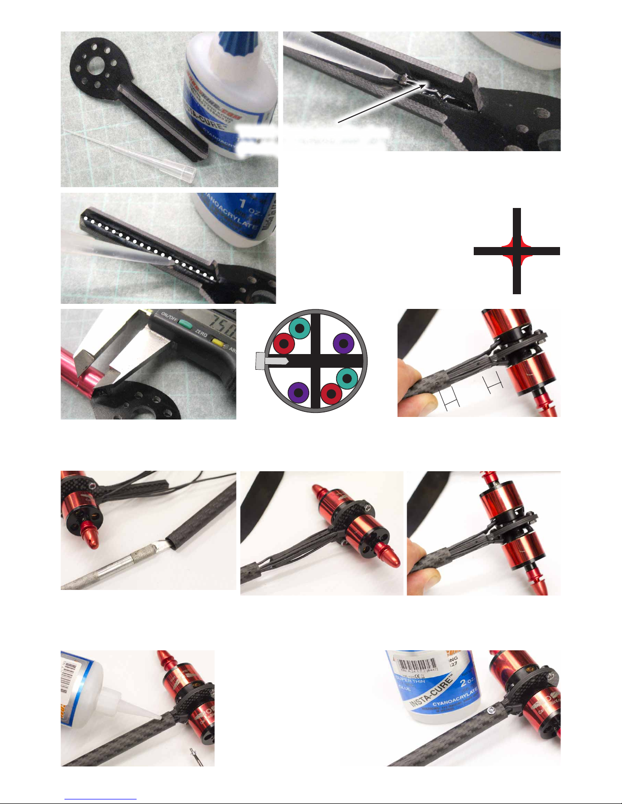
(above left) - counter sink two matching holes
in the engine mount by aligning the wires to the
shaft side of the key shape - Attach the motor - use
Loctite on the screws and also on the shaft lock screw.
Slide the carbon boom over the completed assembly
including the wires - be sure not to cut the wires on
the carbon shaft ! see next page for photos
top engine red
bottom engine black

Page 2
version 1.0.5.1 SCARAB YSiixKopta Airframe guide www.MultiCopterPilot.com
Apply one drop of
thin cyno then apply
the screw lightly. Very
little force is required.
Cyno can be softened
with Acetone for
removal
THIN Cyno-acrylic glue
(HobbyKing superglue)
dry-fit the motor mounts - mark
the hole 7.5mm from the end of the
boom
use a blade to bevel the shaft -
this will prevent the wire insulation
from being cut when fed over
carefully drill a 2.0mm hole
- drill 5mm into the side of the
3mm plate.
place wires along holder -
slowly feed the boom over the
wires checking for fit
both holes - are at 7.5mm
from the end
Do not pull the wires -
slowly slide the beveled tube
over the wires - carefully
Thin
CYNO
Thin
CYNO
Thin
CYNO
Thin
CYNO
Composite structure - Bond the two parts of the
engine mounts - use baking paper on the work surface
- Parts comes pre-press fitted - using a thin-nozzle
aplicator apply lines of thin Cyno on
each of the 4 sides of each mount
and allow to wick-in. Allow to dry
fully - do NOT insert the mount while
superglue is wet. Wait 24 hrs if you
do not have accelerant spray. If using
Accerant spray wait 10 mins to allow it
to soak fully into the fibres first.
top
Internal wires 20AWG
Thinner wires
2x5mm Servo Screw
- cut down supplied
7.5
7.5

Page 3
version 1.0.5.1 SCARAB YSiixKopta Airframe guide www.MultiCopterPilot.com
Make a power distribution lead - 5
wires (the fifth wire will be for LEDs/
BEC supply)
use a piece of heat shrink to hold
the wires - then solder so it can fir
inside the XT60
use a piece of heat shrink to hold
the wires - then solder so it can fir
inside the XT60
slide some 5mm heatshrink onto
the multi’s before you solder the
posts - note that the temporary heat
shrink is then removed - before sliding
the final 5mm down

Page 4
version 1.0.5.1 SCARAB YSiixKopta Airframe guide www.MultiCopterPilot.com
finished power lead - the LiPo will
have the male connector - shown for
clarity here
then test fit all the upper
screws - we supply spare shafts
- some of them are not CNC
perfectly and need to swapped out
for the spares. At this point.
Learning the Throttle curve - After
setting your Tx to 1095/1500/1905
in the GUI - do the ESC throttle
learning curve - To calibrate the ESCs
as a group build a multi harnes - a Y
lead - then connect the actual Rx, one
engine - with Throttle at full on the Tx -
then connect the ESC wiring loom - after
two beeps reduce the throttle to idle - 3
or 4 beeps (3S or 4S) then power off
everything. Done
install the metal posts to one plate - leave them fairly
loose. slide the blue holders down and clip them in
place - they are not symetrical - there are left and right
halves! - then the ESC and the 2mm female connectors
- use FLUX paste to ensure you have a good solder join -

Page 5
version 1.0.5.1 SCARAB YSiixKopta Airframe guide www.MultiCopterPilot.com
Gear - install it default
or cut it shorter. use
the 10mm M2 bolts
and be sure to use
the SCARAB TOOL
1.57mm - washer are
used here but are not
essential. Install the
gear to the lower plate
use the 5mm standoffs for
PARIS
then the 15mm or 20mm
for the top deck
NOTE : SS M2 button
heads have small
shoulders and can strip
with a M1.5 hex - be
sure to USE the
1.57mm L HEX
provided in the kit -
1/16th “ inch

Page 6
version 1.0.5.1 SCARAB YSiixKopta Airframe guide www.MultiCopterPilot.com
The holders will only fit one way - DO NOT TIGHTEN yet - lower the red holders in place
over the posts. apply 1 screw to hold the booms temorarily. Each boom has six wires - put red heat
shrink on 3 and black heat shink on three so you can identify each engine clearly.
Assemble the PARIS - onto the TOP deck (right) - then rest the engines on something to
position them for the next step.

Page 7
version 1.0.5.1 SCARAB YSiixKopta Airframe guide www.MultiCopterPilot.com
ESC are held by one ZIP-tie - now is the time to connect the ESC to the Rx THRO one at a time
- check the rotation direction of each motor is correct (below) - swap any 2 of the 3 wires to
reverse it. Also a good time to balance the engines.
You need either a sum Receiver or a SUM
encoder to run six engines on a PARIS in
1.8 - Future versions of software will get around
this problem by using the Gimbal PWM outputs

Page 8
version 1.0.5.1 SCARAB YSiixKopta Airframe guide www.MultiCopterPilot.com
3°
3°
3°
MOTOR tilt - BELOW we designed the SCARAB system to use motor tilt - this gives positiveYAW
THRUST control for Aerial photo Ops with very little RPM change required - ALSO allows the pilot
to trim the neutralYAW position in hardware - not on the Tx. tilt the front nacels forward
3° - final trimming by flight test - hover - trim with TILT. Rear mount is neutral/level
Install the top cover plate - use the SCARAB 1.578mm 1/16th tool ONLY - tighten lightly - final
tignening after settng the rotation angles
1.578mm
1/16” L tool ; or
SCARAB frame TOOL
NOTE : do NOT use 1.5mm metric heli
tools !

Page 9
version 1.0.5.1 SCARAB YSiixKopta Airframe guide www.MultiCopterPilot.com
LiPo - 4S1800-2650 - we recommend a combo of Velcro and the strap - Use a Quannum Telemetry
cell monitor to land when the first LiPo cell is 4.2->3.3v - total voltage is not as good - as one cell goes
down first!!.
NOTE : Carbon can block 2.4Ghz
RF run your Rx antenna well clear of
the carbon plates - do a range check!
Go Pro - You can run your GoPro upside down and
set the mode to upside down in the GoProUserMenu
- we recommend 720p/60fps. For YSiixKopta you
can also mount a GoPro on the rear landing gear or
use the front mount shown above - keep the mount
very firm with NO PLAY - Balancing props is essential
to removing the Gello Effect of the rolling-shutter
CMOS chip in the GoPro - new firmware for GoPro
also helps with Gello.