Foxtech GAIA 160MP User manual

User Manual
V1.0
FOXTECH GAIA 160MP
2021.04

FOXTECH GAIA 160MP User Manual
©2021 FOXTECH All Rights Reserved 1
Product Profile
Introduction
Specications
SystemComponents
Installation
Overview
StarttheInstallation
A3 Functions
CompassCalibration
FlightFunctions
ProtectionFunctions
Flight Control System Checklist
HardwareChecklist
DJIAssistant2Checklist
Appendix
LEDIndicators
Troubleshooting
2
2
3
4
7
7
8
12
12
13
16
18
18
18
19
19
20
Contents

FOXTECH GAIA 160MP User Manual
©2021 FOXTECH All Rights Reserved 2
Product Profile
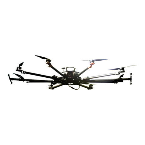
GAIA 160MP is a multipurpose heavy-lift platform. GAIA 160MP Heavy Lift hexacopter is sturdy and has very
good stability. GAIA 160MP is made of carbon fiber material which features light weight and high strength,
and only the cover is made of glass fiber.The arm of GAIA 160MP is pluggable, it can be locked with the
quick locking hooks. This detachable design makes it easy to transport and quick to setup. GAIA 160MP
heavy-lift drone is equipped with powerful motor and high efficiency 30 inch propeller to ensure
long flight time, this heavy-lift drone is able to carry a lot more weight than your typical quadcopter,
max thrust of one rotor can reach 13kg. GAIA 160MP is equipped with dual folding landing gear system, it
has enough space between the center board and the ground. So this strong body can be equipped
with many equipments, like searchlights and loading box,and can be applied in fields like reconnaissance
mission, emergency rescue etc. Besides this, GAIA 160MP also can be used for professional filming
and aerial photography, this GAIA 160MP can load with DJI Ronin 2 gimbal, which is compatible
with many mainstream DSLR and professional cameras with cinema grade glass, like RED Dragon,
Canon C300 and Sony FS7 etc. The motor and ESC adopt the water-resistant design, and can be
applied in different weather conditions. Also the closed fuselage structure can protect GAIA 160-MP
from the rain and dust, and also make it easy to care for.
Introduction

FOXTECH GAIA 160MP User Manual
©2021 FOXTECH All Rights Reserved 3
Aircraft
Structure
Item Name
Wheelbase
Frame Weight
Take-off Weight
Flight Time
Max Effective Load
Max Flying Speed
Battery
Max Lifting Speed
Max Descent Speed
Suggested Flight Altitude Working
Temperature
Hover Precision
GAIA 160MP
1620mm
5.8kg(with landing gear)
48kg
45min(4x6s 16000mah)
30kg
10m/s
4x 6s 16000mah Lipo
5m/s
4m/s
W500m
-10 〜+55 °C
Vertical Direction ±0. 5m, Horizontal Direction: ± 1.5m
Specifications

FOXTECH GAIA 160MP User Manual
©2021 FOXTECH All Rights Reserved 4
System Components
A3 and A3 Pro Parts
Flight Controller Feature Highlights
1. Independent CAN1 and CAN2 ports and API Serial port for the Onboard SDK. The CAN1 port is used to
connect the GPS-Compass Pro and DJI devices (e.g. RTK GPS) while the CAN2 port is used to connect
SDK devices.
2. Built-in inertial sensors for the measurement of aircraft attitude and built-in pressure sensor for the
detection of aircraft altitude.
3. Support for multiple receiver types. If used with the DJI Lightbridge 2, the A3 has direct access to features
in the DJI GO app such as Intelligent Flight Modes.
4. M1 to M8 are used to connect the ESCs of the aircraft and iESC for DJI Intelligent ESC communication.
5. 4 independent and configurable output ports and 4 I/O ports. These ports can be customized and
connect other DJI devices (e.g. DJI Zenmuse Z15 gimbals, DJI Intelligent Landing Gear) or SDK devices.
Port Diagram
1.IMU1 Port
Communicates with the IMU Pro module.
2.CAN1 Port
Dedicated DJI CAN-Bus port. Communicates with the A3 GPS-Compass Pro or other DJI devices (e.g. Real
Time Kinematic (RTK) GPS system).
3.Orientation Arrow
The FC module should be mounted with the arrow pointing in the specified direction (Orientation can be set
in the DJI Assistant 2).
4.Status Indicator
Indicates the status of the flight controller and triple modular redundancy system.
5.RF Port
Communicates with the DJI Lightbridge 2 Air System.
6.iESC Port
Communicates with the DJI Smart ESC.
7.M1-M8 Pins
Connects to the corresponding ESC PWM port for each motor.
8.LED Port
Communicates with the LED module.
9.IMU2 Port
Communicates with the IMU Pro module.
10.PMU Port
Derives power from the PMU.
11.CAN2
Communicates with an SDK device.
12.API Port
Communicates with an Onboard SDK device.

FOXTECH GAIA 160MP User Manual
©2021 FOXTECH All Rights Reserved 5
13.F5-F8 Pins
Multifunction PWM I / O ports.
14.F1-F4 Pins
Multifunction PWM output ports.
15.S-Bus Port
Communicates with a DJI DR16 or S-Bus receiver.
GPS-Compass Pro Module
The GPS-Compass Pro module has a built-in GPS and compass. The compass is used for geomagnetic
field measurements. Compass calibration is required before use. DO NOT use or store the compass in
environments with ferromagnetic materials.
Note that the GPS-Compass Pro module in the UPGRADE KIT is the same as the one in the A3 package.
1.Status Indicator
Indicates the status of the GPS-Compass Pro module and
triple modular redundancy system.
2.Orientation Arrow
The GPS-Compass Pro module should be mounted with the
arrow pointing to the aircraft’s nose.
3.Extended CAN1 Port
Dedicated DJI CAN-Bus port. Communicates with DJI
devices (e.g. Real Time Kinematic (RTK) GPS system).
PMU Module
Supported the LiPo batteries. with built-in PMU providing power for the whole Flight Control System and low
voltage protection function.
1.Power Port (9V 3A)
Connected to the Flight Controller for power supply.
2.iBAT
Reserved.
3. 3S-12S
Derives power from the LiPo batteries.
LED Module
The LED Module has an integrated LED Indicator and Micro USB port.
A.The LED is mainly for flight control system status indication during flight (e.g. Flight Mode).
B.In addition, there is a Micro USB port for firmware upgrades via DJI Assistant 2.
1.Flight Status Indicator
Indicates the status of the flight control system.
2.Micro USB Port
Used to configure and upgrade the A3 or A3 Pro via
DJI Assistant 2.

FOXTECH GAIA 160MP User Manual
©2021 FOXTECH All Rights Reserved 6
IMU Pro Module
Includes built-in inertial sensors for the measurement of aircraft attitude and a built-in pressure sensor for
detecting aircraft altitude. The IMU Pro has been calibrated before delivery and should be used under
the specified temperature range. Using the IMU Pro outside the specified temperature range may have a
negative effect on the IMU’s performance.
1.Orientation Arrow
The IMU Pro module should be mounted with the arrow pointing to the specified orientation (Orientation can
be set in the DJI Assistant 2).
2.Status Indicator
Indicates the status of the IMU Pro module and triple 2 modular redundancy system.
3.CAN1 GPS Port
Communicates with the GPS-Compass Pro module.

FOXTECH GAIA 160MP User Manual
©2021 FOXTECH All Rights Reserved 7
Installation
Overview
Installation Procedure
Read this section carefully and follow the procedures below to install your flight control system, otherwise
the flight control system may not normally work.
①Ensure all parts are in good condition.
②Select the A3 connection.
③Mount the FC parts to GAIA 160MP and connect them properly.
④Launch the DJI Assistant 2 and configure the parameters.
⑤Ensure the motor, remote controller channels and Failsafe settings are correct.
⑥Ensure the devices connected to the flight controller are working normally and correctly set in DJI
Assistant 2.

FOXTECH GAIA 160MP User Manual
©2021 FOXTECH All Rights Reserved 8
Start the Installation
Strictly follow the provided guidelines. Failure to do so may lead to unexpected flight behavior or serious
accidents.
- The top side should be facing up. DO NOT mount upside-down.
- Remember to warm up the battery if operating in cold weather.
- Mount the flight controller at a low vibration position. The sides of the flight controller should be
precisely parallel to the aircraft body. Based on our experience, there is less vibration near the aircraft’s
center of gravity.
- The flight controller is NOT water-proof or oil-proof.
- Check the double-faced adhesive tape regularly to ensure the IMU is fixed firmly in place.
Flight Controller System Installation
Mounting the Flight Controller
Mount the Flight Controller with the Orientation Arrow pointing to the front, back, left or right. Make sure the
module is parallel to the aircraft and then fix it onto the aircraft with double-faced adhesive tape. Configure
the parameters in DJI Assistant 2 and select the direction in which you mounted the Flight Controller. We
recommend mounting the Flight Controller with the Orientation Arrow pointing forward.
Mounting the GPS-Compass Pro Module
Follow the procedures below to mount the GPS bracket and the GPS-Compass Pro module. The GPS-
Compass Pro module included in the Upgrade kits is the same as the one in the A3 package.
1.Use the M2.0〜4 screws to assemble the GPS bracket with the Ball End Hex Key assistant. The longest
one is recommended.
2.With the M2.5〜7 screws and M2.5〜3.4 nuts, mount the bracket on the aircraft.
3.Ensure the GPS-Compass Pro arrow is pointing to the aircraft nose and then fix it onto the top of the GPS
bracket. Try to keep it parallel to the aircraft.
Usage Requirements
1.The DJI logo should be facing the sky, with the orientation arrow pointing directly to the nose direction;
otherwise you may experience take off failure.
2.Fly the aircraft in an open space without buildings or trees; otherwise the GPS may be affected.
3.The compass is sensitive to magnetic interference. Always keep the compass module away from
magnetic fields. Otherwise, the compass module may become damaged and lead the aircraft to work
abnormally or even lose control.
FOXTECH GAIA 160MP User Manual
©2021 FOXTECH All Rights Reserved 9
Mounting the LED Module
Mount the LED module in a position to ensure it remains visible during flight. The LED bracket included can
be used to fix the LED module onto the aircraft.
Mounting the PUM Module
Mount the PMU module to an unobstructed position on the bottom of the aircraft’s upper plate for heat
dissipation.
Mounting the IMU Pro Module
Mount the IMU Pro module with the Orientation Arrow pointing forward, backward, to the left or to the right.
Make sure the module is parallel to the aircraft and then fix it onto the aircraft with double- faced adhesive
tape. Configure the parameters in DJI Assistant 2 and select the direction in which you mounted the Flight
Controller. We recommend mounting the Flight Controller with the Orientation Arrow pointing forward.
Flight Controller System Connection
Follow the below diagram to connect the flight control system, and use the cable ties to tidy the cables.
The flight control system’s shell is connected to the whole system’s ground.
Connecting to the Airframe and its Equipment
Strictly follow the provided guidelines. Failure to do so may lead to unexpected flight behavior or serious
accidents.
Connecting to a Receiver
Select the RF port or the S-Bus port for different types of receivers.
DJI Lightbridge 2
Connect the DJI Lightbridge 2 receiver DBUS port to the Flight Controller RF Port.

FOXTECH GAIA 160MP User Manual
©2021 FOXTECH All Rights Reserved 10
S-BUS Receiver
Connect the S-BUS receiver to the Flight Controller S-Bus Port with a servo cable.
Connecting to the ESCs
Connect the ESC ports to the ESC ports on the Flight Controller in order.
Connecting to a Battery
Connect the PMU to the Flight Controller PMU port, and then connect the battery to the PMU.

FOXTECH GAIA 160MP User Manual
©2021 FOXTECH All Rights Reserved 11
Parameter Configuration
Launch DJI Assistant 2 and follow the prompts to complete configuration.
1. Ensure the flight control system is properly powered on.
2. Connect A3 to a PC.
3. Run DJI Assistant 2. Note that you may be asked to register for first time use.
4. Follow the prompts to upgrade the firmware to the latest version*.
5. Select the airframe type.
6. Configure the IMU and GPS mounting parameters.
7. Select the receiver type and configure the channel mapping.
8. Make sure the motors are rotating in correct direction. If not, change the rotating direction.
9. Configure the function channels.
10. Fly in the simulator to check that all functions is working normally.
Please note that firmware update may reset various Main Controller Settings, such as the RTH Altitude
and Maximum Flight Distance, to factory defaults. Before the update, take note of your preferred
settings, and readjust them after the update to suit your preference.

FOXTECH GAIA 160MP User Manual
©2021 FOXTECH All Rights Reserved 12
A3 Functions
Compass Calibration
Ensure the compass is calibrated before every flight. Failure to calibrate may lead to poor flight performance
or a crash.
1.DO NOT attempt to calibrate your compass where there is a chance of strong magnetic interference.
This includes areas where there are massive metal objects, parking structures, steel reinforcements
underground, or under bridges.
2.DO NOT carry ferromagnetic materials with you during calibration, such as keys or mobile phones.
3.The compass should always be calibrated when moving from indoor spaces to outdoor spaces.
4.After successful calibration, the compass may become abnormal when you place the aircraft on the
ground. This may be because of underground magnetic interference. Move the aircraft to another location
and try again.
Calibration Procedures
Choose an open space to carry out the following procedures.
Using the remote controller (Lightbridge 2 is used here as an example):
1.Quickly flip the control mode switch from P mode to A mode, and then back to P mode three times, and
the Aircraft Status Indicator will display a solid yellow light. Flip the control mode switch between position-1
and position-3 when using the third party remote controllers.
2.Hold and rotate the aircraft horizontally 360 degrees, and the Aircraft Status Indicator will display a solid
green light.
3.Hold the aircraft vertically with nose pointing downward, and rotate it 360 degrees around the center axis.
Recalibrate the compass if the Aircraft Status Indicator is solid red.
Using DJI GO (Lightbridge 2 is required):
Tap the Aircraft Status Indicator bar in the DJI GO app and select “Calibrate”, then follow the on- screen
instructions.
- If the Aircraft Status Indicator blinks red and yellow after the calibration, move your aircraft to a different
location to carry out compass calibration.
- Calibrate the compass before each flight. Launch DJI GO App, follow the on-screen instructions to
calibrate the compass.

FOXTECH GAIA 160MP User Manual
©2021 FOXTECH All Rights Reserved 13
When to Recalibrate
1.When compass data is abnormal, and the Aircraft Status Indicator is blinking red and yellow.
2.When flying in a new location, or a location that is different from your last flight.
3.When the mechanical structure of the A3/A3 Pro has changed, i.e. the mounting position of the compass
has changed.
When severe drifting occurs in flight, i.e. the A3/A3 Pro does not fly in a straight line.
Flight Functions
Flight Modes
Below flight modes are available. Use the Flight Controller mode switch to change
the flight mode of the aircraft. The details of each flight mode are found in the
section below.
Lightbridge 2 is used here as an example.
P mode (Positioning): P mode works best when GPS signal is strong. There are three different states of P
mode, which will be automatically selected by the A3/A3 Pro depending on GPS signal strength and Vision
Positioning sensors:
P-GPS: GPS and Vision Positioning both are available, and the aircraft is using GPS for positioning.
P-OPTI: Vision Positioning is available but the GPS signal is not. Aircraft is using only Vision Positioning for
hovering
P-ATTI: Neither GPS or Vision Positioning available, aircraft is using only its barometer for positioning, so
only altitude is controlled.
A mode (Attitude): The GPS and Vision Positioning System is not used for holding position. The aircraft
only uses its barometer to maintain altitude. If it is still receiving a GPS signal, the aircraft can automatically
return home if the Remote Controller signal is lost and if the Home Point has been recorded successfully.
F mode (Function): Intelligent Flight Mode is activated in this mode.
M mode (Manual): The GPS and Vision Positioning System is not used for holding position. No barometer is
used to maintain altitude. Only use M mode in case of an emergency.
- P-OPTI mode is only available when a DJI Vision Positioning System is used.
- Once the GPS signal is recovered, or the Vision Positioning System available, the Flight Control System
can re-enter P-GPS mode or P-OPTI mode.
- M mode (Manual) should be enabled in DJI Assistant.
Aircraft Status Indicator Description
Normal
x2
Green Flashes Slowly Safe to Fly (P-mode with GPS and Vision Positioning)
Green Flashes Twice Safe to Fly (P-mode with Vision Positioning but without GPS)
Yellow Flashes Slowly Safe to Fly (A mode but No GPS and Vision Positioning)

FOXTECH GAIA 160MP User Manual
©2021 FOXTECH All Rights Reserved 14
Flight Control
Manual Take-off
Start the motors by pulling both control sticks to the bottom inside (or outside) corners. Release the sticks
once the motors start. Slowly push the left stick (throttle stick) up to takeoff.
Remote Controller Operation
Here are the default flight controls (Mode 2). The left stick controls altitude and rotation, while the right stick
controls the forward, backward, left or right movements. The gimbal dial controls the camera’s tilt.
You can customize or change these controls through the DJI GO app.
Manual Landing
Use the below method to stop the motors:
When the aircraft has landed, push the throttle down and hold. The
motors will stop after 3 seconds.
You can use the below method to stop the motors in the event of an emergency.
When the aircraft has landed, push the throttle down, then perform the CSC (Control Stick Combination).
The motors will stop immediately. Release both sticks once the motors have stopped.

FOXTECH GAIA 160MP User Manual
©2021 FOXTECH All Rights Reserved 15
Intelligent Flight Modes (using the Remote Controller)
Intelligent Flight Modes make it easier to operate the aircraft. If you are not using a Lightbridge 2 remote
controller, you will need to configure a 3-position switch on the remote controller as the Intelligent Flight
Modes Switch, with each switch position corresponding to one of the following modes: Off, Course Lock,
or Home Lock.
Course Lock
Use Course Lock to lock the current nose direction as the aircraft’s forward direction. The aircraft will move
in the locked direction regardless of its orientation (yaw angle).
Requirements: Compass must be working properly.
How to operate: 1. Fly the aircraft in the direction you wish to lock; 2. Toggle the Intelligent Flight Modes
Switch to the Course Lock position to lock the current nose direction as the aircraft’s forward direction.
How to reset the parameters: Aircraft nose orientation cannot be reset during flight.
How to stop or exit the flight mode: Toggle the Intelligent Flight Modes Switch to the Off position.
Home Lock
Pull the pitch stick backward to move the aircraft toward its recorded Home Point.
Requirements: Home point recorded; P-GPS mode enabled; distance between the aircraft and Home Point
is greater than 5 meters.
How to operate:
1.Fly the aircraft to the target position;
2.Toggle the Intelligent Flight Modes Switch from the Off position to the Home Lock position for more than
three times to record the Home Point (Note: the Intelligent Flight Modes Switch should stop at the Off
position);
3.Flip the Intelligent Flight Modes Switch to the Home Lock position to start the flight. How to reset the
parameter: Parameters cannot be reset during flight.
How to stop or exit the flight mode: Toggle the Intelligent Flight Modes Switch to the Off position.
Lightbridge 2 not only allows you use the DJI GO app to operate the aircraft, but also use Intelligent
Flight Modes, such as Course Lock, Home Lock, Point of Interest (POI) and Waypoints, to capture
professional shots during flight.

FOXTECH GAIA 160MP User Manual
©2021 FOXTECH All Rights Reserved 16
Protection Functions
Return to Home
Return to Home (RTH) brings the aircraft back to the last recorded Home Point. There are three cases that
will trigger the RTH procedure; they are Failsafe RTH, Smart RTH and Low Voltage RTH with a LiPo battery.
Failsafe RTH
Failsafe RTH is activated automatically if the remote controller signal (including video relay signal if DJI
Lightbridge 2 used) is lost for more than 3 seconds, provided that the Home Point has been successfully
recorded and the compass is working normally. The RTH process may be interrupted and the operator can
regain control over the aircraft if a remote controller signal is resumed.
- The aircraft automatically descends and lands if RTH is triggered when the aircraft flies within a 65-foot
(20-meter) radius of the Home Point.
- The aircraft cannot return to home if the LED is slowly blinking yellow or the GPS does not work.
- The aircraft cannot avoid obstacles during Failsafe RTH. Therefore it is important to set a reasonable
Failsafe altitude before each flight. Launch the DJI GO app and enter “Camera” view and select “MODE”
to set the Failsafe altitude.
- The aircraft will stop ascending and immediately return to the Home Point if you move the throttle stick
when the aircraft reaches an altitude of 20 m or above during Failsafe.
If using the DJI Lightbridge 2, no additional settings are required for the RTH button. If using another
type of remote controller, you must configure the RTH button in DJI Assistant 2.
Smart RTH
Use the RTH button on the remote controller when GPS is available to enable Smart RTH. During the Smart
RTH procedure, the aircraft returns to the last recorded Home Point but you may control the aircraft's
orientation to avoid collisions. Press the Smart RTH button once to start the process. Press the Smart RTH
button again to exit Smart RTH and regain the control.

FOXTECH GAIA 160MP User Manual
©2021 FOXTECH All Rights Reserved 17
Low Battery RTH with LiPo battery
The low voltage failsafe is triggered when the DJI LiPo Battery is depleted to a point that may affect the
safe return of the aircraft. Users are advised to return home or land the aircraft immediately when these
warnings are shown. Aircraft will automatically return to the Home Point if no action is taken after 10 seconds
countdown. Cancel the RTH procedure by pressing once on the RTH button. The thresholds for these
warnings are automatically determined based on the current aircraft altitude and its distance from the Home
Point.
Aircraft will land automatically only if the current voltage can support the aircraft in landing on the ground
from the current altitude. Use the remote controller to control the aircraft’s orientation during the landing
process.
When the critical battery level warning activates and the aircraft is descending to land automatically,
you may push the throttle upward to hover the aircraft and navigate it to a more appropriate location for
landing.
Attitude Control When One Motor Output Fails
For multirotor aircraft, the A3/A3 Pro flight control system can control the aircraft’s attitude when one motor
fails:
1.During flight, the aircraft with A3/A3 Pro flight control system is attitude controllable when one motor
output fails
2.The motor will not start before take-off. (DJI Intelligent ESCs are required for communication.) Select
Course Lock or Home Lock mode to fly the aircraft to a safe area to land when the aircraft is far away, or
the attitude can’t be recognized.
Propulsion System Protection
Low voltage and overweight aircraft warnings are provided in the DJI GO app.

FOXTECH GAIA 160MP User Manual
©2021 FOXTECH All Rights Reserved 18
Flight Control System Checklist
Hardware Checklist
DJI Assistant 2 Checklist
Mounting and components checklist
1.Ensure all parts are mounted correctly and firmly.
2.Ensure the ESCs and receiver are connected correctly and firmly.
LED Status checklist
1.Ensure the mode switch corresponds to the flight status LED.
2.System status LED on the GPS-Compass Pro and IMU Pro are normal.
3.Ensure all the sensor parameters are correct and the IMUs are calibrated correctly.
DJI Assistant 2 checklist
1.Ensure the aircraft mounting parameters are correct.
2.Ensure the flight controller parameters are correct.
Low voltage protection and Failsafe protection are set correctly.

FOXTECH GAIA 160MP User Manual
©2021 FOXTECH All Rights Reserved 19
Appendix
LED Indicators
Flight Status LED Indicator
LED Description
......Blinking Red, Green and Yellow
x4...... Blinking Yellow
......Blinking Green Slowly
......Blinking Yellow Slowly
x2......Blinking Green Quickly Twice
......Blinking Purple Twice
......Blinking Blue (Alternates with flight mode patterns)
......Blinking Blue Rapidly for 1.5 seconds
......Blinking Green Rapidly for 1.5 seconds
......Blinking Yellow (Alternates with other
flight mode and D-RTK patterns)
......Blinking Yellow Rapidly
......Blinking Red Slowly
......Blinking Red Rapidly
......Blinking Red Rapidly for 0.6 second
when performing CSC
—— Solid Red
......Blinking Red and Yellow Alternatively
The system is running a diagnostic test.
Four Times The system is warming up.
Safe to fly, GPS working
P-ATTI or ATTI mode
VPS working, no GPS
Manual mode
Positioning with D-RTK
Switching devices (IMU or GPS modules)
for the modular redundancy system
Home Point/POI/Course Orientation is set
successfully
Intelligent Flight Modes
Remote controller signal lost
Low voltage warning
Critically low voltage warning
Large IMU bias or IMU initialization
Critical error
Compass calibration required
P
GPS-Compass Pro/IMU Pro/Flight Controller LED Indicator
LED Indicator
Green
Red
Blue
The module is functioning normally and working as a part of the system When the LED
is blinking green.
The module is functioning abnormally When the LED is blinking red.
The module is functioning normally but not working as a part of the system When the
LED is blinking blue.
Status
Table of contents
Other Foxtech Drone manuals

Foxtech
Foxtech AYK-250 VTOL User manual

Foxtech
Foxtech GAIA 160AG User manual

Foxtech
Foxtech GAIA 160AG User manual

Foxtech
Foxtech GAIA 190MP User manual

Foxtech
Foxtech Baby Shark 260 VTOL User manual

Foxtech
Foxtech THEA 160S User manual

Foxtech
Foxtech THEA-130 User manual

Foxtech
Foxtech Nimbus VTOL V2 User manual

Foxtech
Foxtech Thor 210 User manual

Foxtech
Foxtech GAIA 160HY-Hybrid A3 PRO User manual