Carco 30B User manual

INSTALLATION AND
PARTS MANUAL
MODEL 30B
FOR
JI CASE 650K/750K/850K
TABLE OF CONTENTS
Adapter Group . . . . . . . . . . . . . . . . . . . . . . . . . . . . . . . . . . . . . . . . . . . . .3
Mounting Group . . . . . . . . . . . . . . . . . . . . . . . . . . . . . . . . . . . . . . . . . .4-6
Control Group . . . . . . . . . . . . . . . . . . . . . . . . . . . . . . . . . . . . . . . . . . .8-10
PRINTED IN U.S.A.
COPYRIGHT 2008 PACCAR WINCH DIVISION.
ALL RIGHTS RESERVED. LIT2171 REV 3
10/2008
PACR WINCH DIVISION
P.O. BOX 547 BROKEN ARROW, OK U.S.A.74013
PHONE (918) 251-8511 FAX (918) 259-1575
www.paccarwinch.com
30B-PS
(31.047 base ratio)
0
Basic
Bevel
0-OVERWIND
0-WITHOUT TOWING HITCH
C
0
0
1-WITH TOWING HITCH
Winch
Gear Ratio
0-HAUL-IN
1-PAY-OUT
Model
0
0
0-FOUR SHAFT WINCH
0-NO FAIRLEAD
1-THREE SHAFT WINCH
3 - 3 ROLLER
4 - 4 ROLLER
(17.249 base ratio)
C-1.64:1
D-2.11:1
E-2.79:1
MODEL NUMBER DESCRIPTION
CARCO
NOTE: This manual covers mounting and control group installation, and parts specific to this
winch on the specified tractor. For all other winch parts, refer to Winch Parts Manual,
Publication LIT2116.
<

THIS PAGE INTENTIONALLY LEFT BLANK
2

ADAPTER GROUP
5
2
4
61
9
10
3
11 7
8
DETAIL A
SEE
DET. A
OIL LEVEL
ITEM NO. PART NO. DESCRIPTION QTY.
1 26133 PTO PILOT 1
2 72251 BEARING 1
3 26165 SEAL 1
4 26128 SLEEVE 1
5 13838 O-RING 1
6 26169 GASKET, PTO PILOT 1
7 104174 CAPSCREW, HEX HD (1/2 - 13 X 1 1/4, G8) 4
8 11026 LOCKWASHER (1/2) 4
9 25491 CAPSCREW, FLAT HD (5/8 - 11 X 2 in., G8) 1
10 100984 RETAINER 1
11 104990 YOKE 1
3

4
MOUNTING GROUP
ITEM NO. PART NO. DESCRIPTION QTY.
1 105720 BRACKET, LH 1
2 105721 BRACKET, RH 1
3 104995 DRIVESHAFT 1
4 103822 END YOKE 1
5 106290 RETAINING RING 1
6 105678 WASHER 1
7 104691 SCREW, METRIC, HEX SOCKET FLAT HD (M12 X 1.75 X 25 MM, 10.9) 1
8 101838 BEARING STRAP & BOLT KIT 2
9 104417 GUARD 1
11 105683 SCREW, METRIC HEX HD (M20 X 2.50 X 60 MM, 10.9) 10
12 103261 WASHER, HARD (M20) 10
13 104893 SCREW, METRIC HEX HD (M12 X 1.75 X 50 MM, 10.9) 2
14 102987 WASHER, HARD (1/2) 13
15 103258 STUD 4
16 100856 WASHER, HARD (3/4) 4
17 103259 NUT, HEX (3/4) 4
18 103257 STUD 4
19 101439 NUT, HEX (1/2) 4
20 104174 CAPSCREW, HEX HD (1/2 - 13 X 1-1/4, G8) 6
21 101337 U-JOINT, BEARING KIT (WINCH END) 1
22 27045 U-JOINT, BEARING KIT (TRACTOR END) 1
22
4
14
5
7
63
8
WINCH INPUT YOKE
21
OPTIONAL FAIRLEAD
OPTIONAL DRAWBAR KIT
TRACTOR PTO OUTPUT
SHAFT
(HYDRAULIC PUMP
THROUGH-SHAFT)
SEE INSTRUCTIONS, ITEM 12
DO NOT OVER-TIGHTEN WINCH INPUT YOKE
MODIFIED TRACTOR PTO COVER
(DIFFERENT FOR EACH TRACTOR)
TYPICAL WINCH DRIVESHAFT LOCATION
(DIFFERENT FOR EACH TRACTOR)
TRACTOR PTO ACCESS HOLE

MOUNTING GROUP
INSTALLATION INSTRUCTIONS:
1. Observe general service methods and safety precau-
tions given in Case / New Holland Tractor Service
Manual.
2. Dimensions in inches (mm).
3. PTO rotation is counter-clockwise (CCW) as viewed
from the rear of the tractor.
4. Remove paint, rust, dirt and oil from mounting sur-
faces of tractor, winch and winch mounting brackets.
Clean threads in mounting fastener holes in winch
and rear face of tractor. Use a tap if necessary. Make
certain all mounting fastener holes are clean and dry.
5. Tighten all fasteners to the torque valves listed in the
following chart, unless otherwise noted.
6. Remove (8) shipping fasteners from the front face of
the winch (outer 2 bolts on each side of top and bot-
tom rows of bolts).
7. Apply Loctite 243 or equivalent to the clean, dry
threads of studs (items 15 & 18), and install into the
winch such that the studs bottom out in the holes. If
the studs supplied have a heavier chamfer on one
end, install the end with the heavier chamfer into the
winch. The studs MUST bottom out in the holes.
8. Test fit the winch mounting brackets (items 1 & 2) to
the winch. Check for interference between the brack-
ets and winch adapter casting, specifically near the
winch center. Lightly grind the brackets and winch
adapter casting as required to provide the clearance
needed to allow the mounting brackets to bolt flush to
the winch.
9. Remove any installed accessories from the rear face
that will interfere with winch mounting. Remove the
tractor rear cover and retain the bolts for later use.
Remove the small PTO cover from the tractor rear
cover and retain the bolts for later use.
10. Assemble the retaining ring (item 5) into the yoke
(item 4) as shown.
11. Coat the splines of the tractor PTO shaft and the yoke
(item 4) with multi-purpose grease. Install the yoke
onto the tractor shaft as shown.
12. Install the large washer (item 6) against the retaining
ring. Then install the smaller washer (item 14) onto
the bolt. Apply Loctite 243 or equivalent to bolt
threads.
13. Attach the driveshaft (item 3) to the yoke assembly as
shown, using the cap and bolt kit (item 8). Apply
Loctite 243 or equivalent to the bolt threads.
14. Guide driveshaft through PTO access opening in trac-
tor rear cover and reinstall the rear cover to the trac-
tor using the existing fasteners. Do not replace fas-
teners that will interfere with the winch mounting
brackets.
15. Ensure that the driveshaft is fully retracted and resting
on the bottom of the PTO access opening in the trac-
tor rear cover.
16. Install the winch mounting brackets (item 1 & 2) to the
tractor rear face as shown, using capscrews (items 11
& 13) and washers (items 12 & 14). Torque the
mounting bolts per note 5.
MOUNTING GROUP
FASTENER SIZE TORQUE (FT-LB) TORQUE (N-M)
3/4 - 10 UNC, GR8 280 379
1/2 - 13 UNC GR8 80 108
5/16 - 24 UNF GR8 18 25
M20X2.5 GR10.9 340 460
M12X1.75 GR10.9 74 100
TORQUE SPECIFICATIONS
Each mounting bracket weights approximately 95
lbs. (43 kg). Use proper safety precautions when
handling to prevent injury.
CAUTION
Each mounting bracket weighs approximately 95 lbs.
(43 kg). Use proper safety precautions when handling
to prevent injury.
A CARCO 30B winch weighs approximately 1,000
lbs. (454 kg) without oil, cable, tractor adapters and
accessories. Make certain your lifting equipment has
adequate capacity. Attempting to lift the winch with
inadequate equipment may result in personal injury or
damage to the winch or property.
5
CAUTION

17. Guide the winch into position on the winch mounting
brackets.
18. Fasten the winch to the brackets using the nuts (items
17 & 19) and washers (items 14 & 16). Torque the
nuts per note 5.
19. Attach the winch driveshaft to the winch input yoke
using the cap and bolt kit (item 8). Apply Loctite 243
or equivalent to the bolt threads.
20. Measure the vertical and horizontal position of the
winch driveshaft as it passes through the tractor rear
cover relative to the mounting holes for the small trac-
tor PTO access opening cover. NOTE: The driveshaft
typically will NOT be centered within the PTO access
opening and the location of the driveshaft can vary
between tractors.
21. Transfer the measured dimensions to the PTO
access cover and cut a hole that is ¼ in. (6 mm) larg-
er than the largest diameter of the driveshaft at the
point that it passes through the tractor rear face. If
required, grind clearance in the tractor rear face
cover.
22. Using a saw, cut the PTO access opening cover in
half vertically to allow for installation around the drive-
shaft. Install the PTO access cover to the tractor rear
face using the existing hardware.
23. Install the bottom guard (item 9) as shown, using fas-
teners (items 14 & 20).
24. Before operating the winch, be sure the winch is filled
to the proper level with the recommended oil.
To prevent serious damage to winch, do not run the
tractor engine without oil in the winch.
MOUNTING GROUP
6
CAUTION

THIS PAGE INTENTIONALLY LEFT BLANK
7

8
CONTROL GROUP
63469 63470
1 26214 VALVE ASSEMBLY 1 1
2 105006 PLATE 1 1
3 104383 BRACKET 1 1
DECAL 1
104381 DECAL 1
5 104253 CAPSCREW, 5/16 UNC X 2 3/4, GRB, Z 3 3
6 100858 WASHER, 5/16 NOM, HARD, Z 9 9
7 104254 NUT, HEX, 5/16 UNC, GR8, Z 3 3
8 103749 CAPSCREW, 3/8 UNC X 7/8, GRB, Z 2 2
9 101440 WASHER, 3/8 NOM, HARD, Z 4 4
10 PA6V8801 NUT, HEX, 3/8 UNC, GR8, Z 2 2
11 25665 PLUG, -6ORB 1
12 26680 ELBOW 90, -4ORFS/-4ORFS 4 3
14 26682 ELBOW 90, -4ORFS/-4ORFS 2 1
15 26681 ADAPTER, -80RB/-4ORFS 2 2
16 105028 HOSE ASSY, -4ORFS X 106" 6 5
17 26678 ADAPTER, -4NPT/-4ORFS 2 2
18 104255 ELBOW 90, -4NPT/-4ORFS 3 3
19 104261 ELBOW 90, SPECIAL FOR ORIFICE PLUG 1
20 105056 ORIFICE PLUG, ø, 070 1
22 40240 CAPSCREW, BUTTON HEAD, 1/4 UNC X 1, Z 4 4
23 100857 WASHER, 1/4 NOM, HARD Z 4 4
24 105012 NUT, HEX, 1/4 UNC, GR8 Z 4 4
25 105011 SCREW, SELF TAPPING, #10 X 1/2 4 4
26 105003 BOOT, RUBBER 1 1
27 105004 PLATE 1 1
28 105013 BUSHING, RUBBER 1 1
29 32235 ZIP TIE 6 6
4
QTY. REQ'D
DESCRIPTION
PART NO.
ITEM NO.

CONTROL GROUP
9
CONTROL GROUP
INSTALLATION INSTRUCTIONS
1. Observe general service methods and safety precau-
tions given in Case / New Holland tractor service
manual.
2. Access to space below operator platform may be
gained by tilting the operator platform per the tractor
service manual.
3. Assemble the winch controller as shown in Detail C.
Leave the control handle loose. NOTE: A) It may be
easier to install the rubber bushing (item 28) by
removing the knob and slipping the bushing over the
small threads at the top end of the rod. B) The cap-
screws and washers (items 8 & 9) are loose, but cap-
tured in their holes by the top of the valve body.
4. Remove the top plastic cover from the RH tractor con-
sole.
5. For EROPS machines only, remove the ashtray, steel
ashtray opening surround, and cigar lighter assembly
from the plastic console cover.
6. With a 3 in. (76 mm) hole saw, cut the opening in the
console top steel plate, as defined. Drill the mounting
holes using a 7/16 in. (12 mm) drill bit. NOTE: A)
Dimensions are measured from the start of the indi-
cated bend in the console top plate. B) On EROPS
tractors only, it will be necessary to trim the foam insu-
lation away from the winch controller mounting area
on both the top and bottom of the console top plate.
7. Install the winch controller assembly into the tractor
console opening using nuts and washers (items 9 &
10).

CONTROL GROUP
10
8. Remove the winch controller handle from the assem-
bly.
9. Test fit the plastic console cover to the RH console.
NOTE: On EROPS tractors, the winch controller
assembly will be visible through the ashtray
opening in the plastic console cover. On OROPS
tractors, the winch controller assembly will not be
visible.
10. On OROPS tractors, mark the approximate location
where the winch controller handle, in its neutral posi-
tion, will protrude through the console cover. Cut a 3
in. (76 mm) diameter opening in the plastic cover
using a hole saw or suitable method.
11. Temporarily replace the winch controller handle into
the control assembly.
12. While ensuring the controller handle is in the neutral
position, center the gate plate (item 2) over the con-
troller handle as shown in View A. Once positioned,
use the gate plate as a template to transfer the mount-
ing hole locations (4 holes) to the plastic console
cover. Drill (4) 5/16 in. (8 mm) holes in the locations
marked. Also, be sure to remove any excess plastic
beneath the gate plate within the shift pattern.
13. Modify the cigar lighter boss as required to allow the
gate plate to fit flush to the top of the console cover.
14. Install the gate plate to the plastic cover with cap-
screw, washers and nuts (items 22, 23 and 24) as
shown in View A.
15. Re-install the controller handle into the control valve
assembly and tighten the jam nut.
16. Install the boot and boot retainer plate (items 26 & 27)
to the gate plate using self-tapping screws (item 25)
as shown in View B.
17. Stretch the top of the rubber boot over the rubber
bushing previously installed on the handle, and attach
the boot to the bushing to seal and retain the top of
the boot.
18. Affix the decal (item 4) to the console near the winch
controller, or to the inside of the window. The opera-
tor's view of the decal MUST be clear and unobstruct-
ed.
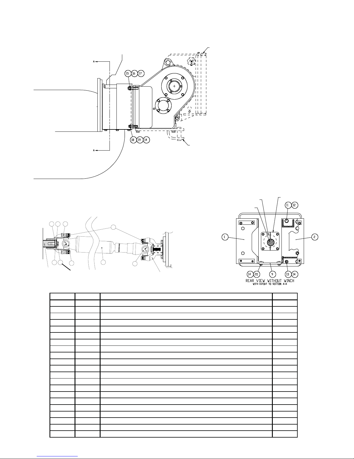
19. Install hydraulic fittings to the winch face and control
manifold, as shown in Detail “D”.
NOTE: If the winch is equipped Reel-Out, then
install the orifice plug (item 20) into the special
elbow (item 19) using Loctite 572 or equivalent.
20. Tilt the cab as outlined in the tractor manual.
21. Install the winch control hoses (item16) to the proper
ports as defined in Details “C” and “D”. Route the
hoses around the rear of the operator platform, down-
ward near the cab tilt hinge on the LH side of the trac-
tor, then back to the center of the tractor to pass under
the fuel tank to the winch. Ensure that the hoses will
not be stretched or pinched, or otherwise interfere in
any way with the tilting of the cab during regular serv-
icing.
22. Test the cab tilt function to validate the hose routing.
When satisfied, bundle and affix the hoses as appro-
priate using the tie straps (item 19).
i
i
Table of contents
Popular Tractor manuals by other brands

New Holland
New Holland TB120 Mudder Operator's manual

Wheel Horse
Wheel Horse 854 Operation and Service Manual with Parts List

New Holland
New Holland T3.60F Operator's manual

Gravely
Gravely L 1963 instruction manual

Challenger
Challenger MT755E CE Operator's manual

Challenger
Challenger MT225 Service manual