L371.02 CDR 863 07-2000
CARDIN ELETTRONICA spa
Via Raffaello, 36- 31020 San Vendemiano (TV) Italy
Tel: +39/0438.404011-401818
Fax: +39/0438.401831
email (Italy): Sales.office.it@cardin.it
email (Europe): Sales.office@cardin.it
Http: www.cardin.it
MODÈLE DATEFASCICULE SERIE
Ce produit a été testé et essayé dans les laboratoires de la Maison
Constructrice. Durant son installation, suivre attentivement les instruc-
tions fournies.
DESCRIPTIF
Barrière à l’infrarouge modulé, composée d’émetteur et de récep-
teur sous boîtier en matière plastique antichoc et étanche, prédis-
posé pour tous types de fixation.
La tête optique est réglable aussi bien horizontalement, par rota-
tion de 180°, que verticalement par rotation de ± 30° par rap-
port à la position standard; ce qui permet des installations avec
fonctionnement latéral par rapport à la surface de fixation et des
installations avec émetteur et récepteur montés à des hauteurs
différentes (dét. “D” fig. 3).
DOMAINE D’APPLICATION
La barrière à l’infrarouge modulé est destinée à assurer efficace-
ment la sécurité lors du fonctionnement de systèmes de ferme-
ture automatique de portes et de portails, contrôlés à distance.
Elle peut être appliquée sur des passages d’une largeur maxi. de
10 m. Pour l’utilisation et l’installation de ces appareils, se confor-
mer scrupuleusement aux indications fournies par le Fabricant et
aux normes de sécurité en vigueur. Le Fabricant ne peut en aucun
cas être tenu responsable de dommages éventuels causés par
des utilisations impropres, erronées ou illogiques.
VERSIONS
CDR863. Le carton comprend:
- 1 émetteur sous boîtier de base
- 1 récepteur sous boîtier de base
- un sachet de vis;
- un sachet de joints.
CARACTÉRISTIQUES TECHNIQUES
- Émission infrarouge par diode GaAIAs (arséniure de gallium) à
double émetteur, avec modulation continue 4,7 kHz.
- Longueur d’onde de l’émission infrarouge: 950 nm.
- Alimentation: 12/24 Vac/dc.
- Puissance maxi. commutable par le relais avec charge
résistive:
24 W en dc / 60VA en ac; tension maxi. 30 Vac/dc.
- Contact de sortie: C-NO-NF; double relais avec contact inver-
seur en série.
- Intensités absorbées:
en 12 Vac/dc: 65 mA l’émetteur, 23 mA le récepteur
en 24 Vac/dc: 68 mA l’émetteur, 29 mA le récepteur
- Température de fonctionnement: -10 ... +55°C.
- Voyant rouge de signalisation mise sous tension, sur émetteur.
- Voyant rouge (cellule photoélectrique non alignée ou rayon
interrompu), sur récepteur.
- Test point (pour centrage de précision) sur récepteur.
- Tête optique réglable, montée sur pivot orientable autoblo-
quant.
- Portée: 10 m en toute condition atmosphérique, même en cas
d’épais brouillard, d pluie ou d’environnement poussiéreux.
- Indice de protection: IP55.
MONTAGE
Généralement l’émetteur et le récepteur sont fixés sur le même
axe géométrique, à la même hauteur du sol et en façade.
En cas d’installation comprenant plusieurs appareils, il est à
signaler que deux récepteurs montés du même côté peuvent être
soumis à l’action du même projecteur, monté du côté opposé,
sans que ceci soit préjudiciable au bon fonctionnement du sys-
tème.
Toutefois, si cette solution n’est pas visée, éviter ces interférences
en montant les émetteurs et les récepteurs à la juste distance
(min. 600 mm).
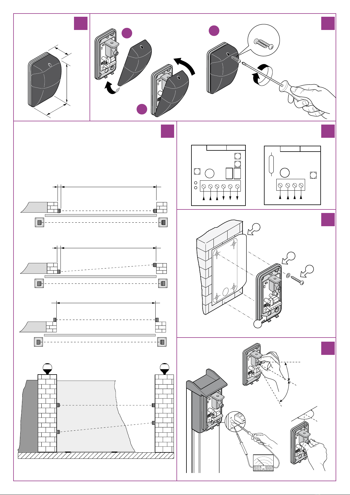
MONTAGE EN SAILLIE
La barrière peut être montée sur toute structure, permettant,
outre le positionnement standard, également le positionnement
latéral (en installant les appareils hors du passage), ainsi que le
positionnement émetteur/récepteur à des hauteurs différentes;
ceci pour solutionner les problèmes sur structures particulières
(dét. a-b-c-d, fig. 3).
• Pour un montage correct, suivre scrupuleusement les instruc-
tions suivantes:
Attention! Ne jamais enlever la carte électronique de son
support.
- pour l’ouverture et la fermeture des boîtiers, voir figure 2,
- déterminer les points de fixation selon la particularité de l’ins-
tallation,
- prévoir le chemin des câbles sur la structure jusqu’aux points
de fixation,
- à l’aide du gabarit de perçage qui se trouve dans la boîte, tracer
les trous de fixation (“D” fig. 5),
- fixer l’embase avec le relatif joint au mur (“A” fig. 5) après avoir
passé les câbles de branchement à travers le trou “B” prévu
à cet effet. Pour la fixation, utiliser exclusivement les vis et les
rondelles qui se trouvent dans la boîte.
- effectuer les branchements électriques (fig. 4),
- aligner correctement l’émetteur et le récepteur en intervenant
sur la tête optique et vérifier ensuite si l’articulation de la tête
optique est bien serrée (fig. 6),
- remettre le verre à sa place sur la base. Pour ce faire, appliquer
la partie basse du verre sur le joint et ensuite le pivoter jusqu’au
déclic (voir “A” fig. 2),
- pour la fixation du verre, utiliser exclusivement les deux vis qui
se trouvent dans la division supérieure du sachet à vis (voir dét.
“1” fig. 2).
ESSAI ET MISE AU POINT (fig. 4)
- Une fois que le montage a été effectué, s’assurer de l’efficacité
de l’installation.
Si la structure est irrégulière, il est préférable de faire un con-
trôle du fonctionnement électrique avant de fixer définitivement
les appareils. Ensuite, après avoir branché et fixé l’émetteur,
brancher le récepteur. Après quoi, procéder de la façon sui-
vante.
Une fois que l’émetteur et le récepteur sont sous tension, le
voyant de l’émetteur est allumé en continu; le voyant du récep-
teur est éteint lorsque la cellule photoélectrique est centrée
(système en veille) et allumée lorsque la cellule photoélectrique
n’est pas centrée.
- Effectuer toujours, au moment de la pose, le contrôle du cen-
trage en procédant de la façon suivante:
1)Introduire les extrémités d’un testeur analogique (2 Vdc valeur
maximale) dans les zones expressément prévues pour l’essai
(test point), en respectant la polarité indiquée sur la carte (fig.
6);
2)Lire la valeur indiquée sur le testeur; une tension de 0,95 Vdc
est la valeur optimale. Si la tension mesurée est supérieure,
atténuer le signal en modifiant l’orientation de la tête optique
du récepteur, jusqu’à obtenir la valeur de tension optimale.
S’il n’était pas possible d’obtenir la valeur indiquée pour quel-
que raison liée à la particularité de l’installation, il serait préfé-
rable de l’augmenter légèrement en veillant toutefois à rester
au-dessous de la tension maximale de 1 Vdc.
Nota: aucun élément fixe ne doit être interposé entre récepteur
et émetteur.
S’il est nécessaire d’appliquer des protections antichoc suscep-
tibles d’interférer dans le faisceau, contacter un de nos techni-
ciens.
BARRIÈRE À L’INFRAROUGE MODULÉ