Cardin Elettronica RADIOSHIELD Series User manual

1
CARDIN ELETTRONICA S.p.A
Via del lavoro, 73 – Z.I. Cimavilla - 31013 Codognè (TV) Italy
Tel: +39/0438.404011 / Fax: +39/0438.401831
®
The RADIOSHIELD series conforms to the essential requirements of the directive 99/05/CE
and the technical reference standards have been applied.
Frequency validity: 433,92 - 868,3 MHz for all countries
MODEL DATE
SERIAL Nr. NAME
RADIOSHIELD CDR4 - CDR8
03.03.2014
ZVL549.01
FOTOCELLULA DI SICUREZZA SENZA FILI RADIOSHIELD
Messa in funzione ed uso pagine 2-10
Disegni tecnici d'installazione e riferimento pagine 39-45
RADIOSHIELD WIRELESS SAFETY PHOTOELECTRIC CELLS
Set up and user instructions pages 11-19
Installation and reference drawings pages 39-45
CELLULES PHOTOÉLECTRIQUES DE SÉCURITE SANS FIL RADIOSHIELD
Mise en service et utilisation pages 18-28
Dessins techniques d’installation et référence pages 39-45
DRAHTLOSE SICHERHEITSLICHTSCHRANKE RADIOSHIELD
Inbetriebnahme und Benutzung Seiten 29-37
Technische Installations- und Referenzzeichnungen Seiten 39-45
FOTOCÉLULA DE SEGURIDAD INALÁMBRICA RADIOSHIELD
Puesta en función y uso páginas 38-46
Dibujos técnicos de instalación y referencias páginas 47-53
www.cardin.it

2
Avvertenze
Il presente manuale si rivolge a persone abilitate all'installazione di "Apparecchi utilizzatori di energia
elettrica"e richiede una buona conoscenza della tecnica, esercitata in forma professionale. L'uso ed
installazione di questa apparecchiatura deve rispettare rigorosamente le indicazioni fornite dal costruttore e
le normative di sicurezza vigenti.
Attenzione! Solo per clienti dell’EU - Marcatura WEEE.
Il simbolo indica che il prodotto alla ne della propria vita utile deve essere raccolto separa-
tamente dagli altri riuti. L’utente dovrà pertanto conferire l’apparecchiatura agli idonei centri
di raccolta differenziata dei riuti elettronici ed elettrici, oppure riconsegnarla al rivenditore al
momento dell’acquisto di una nuova apparecchiatura di tipo equivalente, in ragione di uno
a uno. L’adeguata raccolta differenziata per l’avvio al riciclaggio, al trattamento e allo smaltimento
ambientalmente compatibile contribuisce ad evitare possibili effetti negativi sull’ambiente e sulla
salute e favorisce il riciclo dei materiali. Lo smaltimento abusivo del prodotto da parte del detentore
comporta l’applicazione delle sanzioni amministrative previste dalla normativa vigente nello Stato
Comunitario di appartenenza.
Descrizione
Il sistema Radioshield è conforme alla norma di sicurezza EN12978 ed è composto di un’u-
nità ssa e di una o più coppie di fotocellule (proiettore e ricevitore) per ogni passaggio da
proteggere nell’impianto. L’unità ssa può gestire no a 8 coppie di fotocellule raggruppabili
in fase di memorizzazione in tre gruppi differenti: ogni gruppo di fotocellule viene associato
a una sola uscita (OUT1, OUT2 o OUT3) tramite dip-switch. L’unità ssa e le fotocellule
sono alloggiati in contenitori di plastica antiurto con grado di protezione IP65. I coperchi
delle unità ssa sono semitrasparenti così da permettere la visualizzazione dello stato delle
sicurezze e del livello di carica della batteria tramite led.

3
Possibilità d'impiego
La trasmissione radio tra fotocellule e l’unità ssa consente di eliminare ogni tipo di colle-
gamento a lo tra una o più entrate protette e il programmatore.
Il sistema è composto di:
SAFECDR4-CDR8 Coppia di fotocellule transceiver a supercie
SAFEDECX4-DECX8 Unità transciever ssa
ZRA3.0-3.8-W Pacco batteria litio 3V
ANS-400 / ANQ800-1 AntennA esterna opzionale per transceiver 433 - 868 MHz
Modulo di memoria (MM)
Situato a bordo dell’unità ssa, è costituito da una memoria non volatile di tipo EEPROM,
permette di memorizzare no a 8 coppie di fotocellule nell’unità transceiver ssa. Nel modulo
i codici vengono mantenuti anche in assenza di alimentazione.
INSTALLAZIONE TRANSCEIVER-ANTENNA
Portata massima: 30 metri in campo aperto.
Èbuonanormaposizionarel’unitàssaadebitadistanzadareti di sistemi computerizzati,
da impianti d’allarme e da altre forme di possibile disturbo.
L’unità ssa viene fornita con un lo antenna collegato su apposito morsetto (12).
Per aumentare la portata è possibile installare un’antenna esterna accordata ANS-400
/ ANQ800-1 mediante cavetto coassiale RG58 (impedenza 50Ω) di lunghezza max. 15
m; in questo caso posizionare l’antenna il più lontano possibile da strutture metalliche
in un punto raggiungibile a vista dal maggior numero di fotocellule in uso.
Portata fotocellule: 10 m in tutte le condizioni atmosferiche.

4
Installazione unità fissa (fig. 2)
Stabilire il punto di ssaggio a supercie in base alla necessità d’impianto, quindi:
- utilizzando un cacciavite a stella svitare le quattro viti
1
e togliere il coperchio
2
;
- svitare ed estrarre la scheda elettronica e con lo stesso cacciavite aprire i fori presfondati
3
;
- tracciati i due punti di ssaggio con l’ausilio della scatola, eseguire i fori
4
e ssare il contenitore
utilizzando i due tasselli
5
e le viti autolettanti 4,2 x 45 in dotazione
6
.
- inserire la scheda elettronica
7
, eseguire il collegamento elettrico e rimettere il coperchio
utilizzando le quattro viti di ssaggio
8
precedentemente tolte.
Collegamento elettrico unità fissa (fig. 3)
Attenzione! Alimentare l'unità ssa esclusivamente con un alimentatore di sicurezza.
• Collegare l’alimentazione 12 o 24 Vac/dc tra i morsetti 1 e 2.
• Collegare l’uscita o le uscite (OUT1, OUT2, OUT3) ai rispettivi ingressi di sicurezza del pro-
grammatore.
Installazione fotocellule transceiver (fig. 4-8)
In caso di installazioni comprendenti più coppie di fotocellule occorre tener presente, che due
ricevitori installati sullo stesso lato possono essere interessati dall'identico proiettore, montato
sul lato opposto, compromettendo il regolare funzionamento del sistema. Se questa circostanza
non dovesse essere ricercata, si avrà cura di evitare queste interferenze, intercalando alla giusta
distanza proiettori e ricevitori (min 600 mm). Proiettore e ricevitore vanno normalmente ssati
sullo stesso asse geometrico e alla stessa altezza dal suolo, frontalmente. L'installazione è
possibile su ogni tipo di struttura. Il posizionamento proiettore ricevitore può essere anche
non allineato e su quote differenti (vedi g. 4). L'ottica con snodo consente in ogni caso una
perfetta centratura.

5
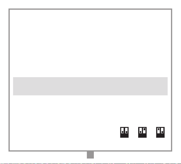
Procedura di montaggio SAFECDR4-CDR8
(fig. 5)
• In base alla necessità d'impianto individuare i punti di ssaggio a muro;
- utilizzando la dima predisposta all'interno dell'imballaggio tracciare i punti per i fori di ssaggio a muro
a seconda delle dimensioni del SAFECDR4-CDR8 riportate in gura 1;
- rimuovere la vite di bloccaggio coperchio
1
;
- ruotare il coperchio verso l'alto
2
e separarlo dalla base
3
;
- utilizzando un trapano con punta da Ø 5 mm effettuare i fori sui punti marcati
4
;
- ssare la base
5
a muro utilizzando le viti e Fisher
6
;
- impostare tutti i DIP-SWITCH a OFF sia sul ricevitore sia sul proiettore;
- inserire il cavo pannello solare
a
ed il cavo pacco batteria
b
(fig.6).
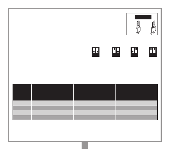
Centratura SAFECDR4-CDR8 (fig. 6, 7, 8)
• Alimentati le fotocellule risulterà: sul proiettore led rosso spento e sul ricevitore led
rosso acceso con fotocellula non centrata o spento con fotocellula centrata.
• Selezionare il livello di sensibilità adeguata alla distanza tra proiettore e ricevitore:
- sensibilità alta H = 8 - 10 m (jumper J2 in posizione 1);
- sensibilità media M = 4 - 8 m (jumper J2 in posizione 2);
- sensibilità bassa L = 0 - 4 m (jumper J2 in posizione 3).
• Inserire il Jumper "J1", accesso alla procedura di centratura, in posizione "1"
• Seguire la centratura nel modo seguente:
- inserire i puntali di un tester (2 Vdc fondoscala) nelle apposite zone di prova
(test point) rispettando l'esatta polarità, come da contrassegni sulla scheda
(TP g. 8), e togliendo il ferma puntali
c
se necessario;
- allentare leggermente le 2 viti
d
se necessario e
centrare le ottiche in
modo da ottenere sul tester la lettura massima considerando
come riferimento i valori riportati in tabella ( i valori sono puramente indicativi
e dipendono dalle condizioni atmosferiche).
• Riavvitare le viti
d
vericando il mantenimento della centratura e inserire il Jumper "J1" in posizione "2".
POS 1 POS 2 POS 3
POS 2POS 1
J2
J1
Sensibilità Distanza Tensione
(m) (V)
H 8 0,9
H 10 0,8
H 12 0,7
M 4 1,0
M 6 0,8
M 8 0,7
L 2 1,0
L 3 0,9
L 4 0,8

6
Memorizzazione di una coppia di fotocellule
1. Portarsi sull’unità ssa e tenere premuto il pulsante P1- fig. 3 nché l’unità ssa emetterà un bip: si entra
in modalità di memorizzazione e il led L1- fig. 3 lampeggerà lentamente.
2. Portarsi sul ricevitore della coppia di fotocellule da memorizzare e premere il pulsante P1: il ricevitore
segnalerà l’avvenuta memorizzazione con l’accensione ssa del led L1 - fig. 6, (acceso per 4 secondi).
Contemporaneamente l’unità ssa emetterà un doppio bip e accenderà i led L3 - fig. 3 di stato sicurezza
e L4 stato batteria relativi alla coppia di fotocellule memorizzata. A questo punto l’unità ssa è pronta per
memorizzare un’altra coppia di fotocellule.
3. Per uscire dalla modalità di memorizzazione attendere 30 secondi o premere il tasto P1 - fig. 3 dell’unità
ssa nché verrà emesso un bip prolungato.
Un errore in fase di memorizzazione verrà segnalato con lampeggio veloce del led dell’interfaccia. In questo
caso ripetere la memorizzazione ripartendo dal punto 2. Alla memorizzazione dell’ottava ed ultima coppia di
fotocellule, l’unità ssa esce dalla memorizzazione e il buzzer emette 10 bip ravvicinati.
Cancellazione via radio di una coppia di fotocellule
1. Portarsi sull’unità ssa e tenere premuto il pulsante P2- fig. 3 nché l’unità ssa emetterà un bip: si entra
in modalità di cancellazione e il led L1- fig. 3 lampeggerà velocemente.
2. Portarsi sul ricevitore della coppia di fotocellule da cancellare e premere il pulsante P1: il ricevitore segnalerà
l’avvenuta cancellazione con l’accensione ssa del led L1 - fig. 6, (acceso per 4 secondi). Contempora-
neamente l’unità ssa emetterà un doppio bip e spegnerà il led L3 - fig. 3 di stato sicurezza e L4 stato
batteria relativi alla coppia di fotocellule cancellata. A questo punto l’unità ssa è pronta per cancellare
un’altra coppia di fotocellule.
3. Per uscire dalla modalità di cancellazione attendere 30 secondi o mantenere premuto il tasto P2 - fig. 3
dell’unità ssa nché verrà emesso un bip prolungato.
Un errore in fase di cancellazione verrà segnalato con lampeggio veloce del led L1 sul ricevitore in questo
caso ripetere la cancellazione ripartendo dal punto 2.
Alla cancellazione dell’ultima coppia di fotocellule l’unità ssa esce dalla modalità di cancellazione e il buzzer
emette 10 bip ravvicinati.

7
Cancellazione manuale di una coppia di fotocellule senza il dispositivo transceiver (fig. 3)
1. Portarsi sull’unità ssa e tenere premuto il pulsante P2 nché l’unità ssa emetterà un bip: si entra in
modalità cancellazione e il led L1 lampeggerà velocemente.
2. Tenere premuto il pulsante P1 nché l’unità ssa emetterà un bip: si entra in modalità di cancellazione
manuale e il led L1 lampeggerà molto velocemente.
3. I led L3 e L4 lampeggiano per indicare la sicurezza attualmente selezionata. Tramite la pressione breve
del pulsante P1 è possibile selezionare ciclicamente la sicurezza che si vuole cancellare.
4. Tenere premuto il pulsante P2 nché l’unità ssa emetterà un doppio bip per segnalare l’avvenuta can-
cellazione della sicurezza selezionata.
5. Per uscire dalla modalità di cancellazione manuale attendere 30 secondi o mantenere premuto il pulsante
P1 dell’unità ssa nché verrà emesso un bip prolungato.
Cancellazione completa della memoria (fig. 3)
1. Tenere premuti entrambi i pulsanti P1+P2 dell’unità ssa per più di 5 secondi.
2. Un bip segnala l’inizio della cancellazione completa della memoria e il led L1 rimane acceso durante la
cancellazione.
3. Il led L1 si spegne: la cancellazione è stata completata.
Segnalazioni L1 sul ricevitore della coppia di fotocellule
- Led acceso sso per 4 s, memorizzazione/cancellazione avvenuta con successo.
- Led lampeggiante veloce per 4 s, memorizzazione/cancellazione non a buon ne.
Segnalazioni LED unità fissa
L1 lampeggio lento, unità ssa nello stato di memorizzazione;
L1 lampeggio veloce, unità ssa nello stato di cancellazione via radio;
L1 lampeggio molto veloce, unità ssa nello stato di cancellazione manuale;
La sua breve accensione indica che è in corso una interrogazione della coppia di fotocellule memorizzate.

8
L2 acceso sso, indica il corretto funzionamento del dispositivo;
L2 lampeggiante, memoria non presente o errore sistema.
L3-L4 sono numerati da 1 a 8 e identicano lo stato della rispettiva coppia di fotocellule memorizzate.
L3 Led rosso di sicurezza sso, coppia di fotocellule memorizzate a riposo;
L3 Led rosso di sicurezza lampeggiante, coppia di fotocellule memorizzate in allarme;
L4 Led verde di stato batteria acceso sso, coppia di fotocellule memorizzate e batteria carica
L4 Led verde di stato batteria lampeggiante lento, coppia di fotocellule memorizzate e livello batteria basso
L4 Ledverdedistatobatterialampeggianteveloce,coppiadifotocellulememorizzateebatteriadasostituire
al più presto (In questo caso il buzzer emette 5 bip ravvicinati ogni 20 secondi).
L3 - L4 spenti, coppia di fotocellule non memorizzate.
ATTENZIONE! Se sono memorizzate sicurezze con rmware non compatibile con la modalità impostata,
sull’interfaccia lampeggeranno i led L3 - L4 corrispondenti alle sicurezze non compatibili e il sistema risulterà
in blocco. In questo caso, impostare la modalità 4 per poter cancellare le sicurezze non compatibili.
Impostazione dip-switch e jumper sulla coppia di fotocellule memorizzate DIP S1, fig. 6
Con i DIP della fotocellule si seleziona l’uscita dell’unità ssa alla quale associare la sicurezza.
Impostare il loro stato prima della memorizzazione della sicurezza stessa.
Nel caso si voglia cambiare l’associazione con l’uscita di un sicurezza già memorizzata:
1. posizionare i dip sul ricevitore secondo la nuova congurazione;
2. cancellare e rimemorizzare la sicurezza.
La nuova impostazione verrà sovrascritta sulla precedente.
1 2
ON
1 2
ON
1 2
ON
OUT1 OUT2 OUT3

9
Dip-Switch S3 Impostazione modalità di funzionamento
1 2 3 4 Modalità Descrizione
ON ON OFF OFF
1Basso Consumo: modalità comunicazione su canale radio differenti per evitare
interferenze - canale 1 per
sicurezze con rmware V3.0 o successivo
.
ON ON ON OFF
2Basso Consumo: modalità comunicazione su canale radio differenti per evitare
interferenze - canale 2 per
sicurezze con rmware V3.0 o successivo
.
ON ON OFF ON
3Basso Consumo: modalità comunicazione su canale radio differenti per evitare
interferenze - canale 3 per
sicurezze con rmware V3.0 o successivo
.
OFF OFF OFF OFF
4
Broadcast: L’unità ssa esegue un controllo sullo stato delle sicurezze ogni
30 secondi. Nel caso di mancata risposta di una o più sicurezze il sistema
imposta lo stato di allarme per la sicurezza o le sicurezze che non rispondono.
OFF OFF ON OFF
5
Broadcast: Come la modalità 4 ma è riservata solamente ad un sistema
composto da sole sicurezze con rmware V2.0 o successivo.
ON OFF OFF OFF
6Carichi controllati: L’unità ssa esegue un controllo sullo stato delle sicurezze
su richiesta della centralina. Solo per sicurezze fotocellule radio.
ON OFF ON OFF
7Carichi controllati:
Come la modalità 6 ma compatibile anche con le sicurezze
costa radio.
ON OFF OFF ON
8
Carichi controllati:
Come la modalità 7 ma l’interfaccia viene alimentata
dall’uscita carichi controllati della centralina. Supporto anche il funzionamento
a batteria.
OFF ON OFF OFF
9Lampeggiante: L’unità ssa esegue un controllo sullo stato delle sicurezze
quando si attiva l’uscita lampeggiante della centralina.

10
Impostazione jumper nell’unità fissa fig. 3
I jumper J1-J2-J3. permettono di selezionare il tipo di contatto per la corrispettiva
uscita.
Pos. 1 – uscita normalmente chiusa a riposo (aperta in allarme)
Pos. 2 – uscita resistiva 8.2K
Ω
a riposo (aperta in allarme)
Attenzione: Per rendere effettive eventuali modiche sui dip è necessario
togliere e ridare l’alimentazione.
Impostazione dip-switch S3 sul trasmettitore
I dip servono per impostare il tempo di intervento e
quindi ottimizzare la durata della batteria.
Attenzione: per rendere effettive eventuali modiche sui dip è necessario mantenere premuto il tasto P2 no
ad un doppio lampeggio del led L2.
Tabella di risparmio energetico della batteria
POS 2POS 1
J1 - J2 - J3
1 2
ON
1 2
ON
1 2
ON
80 ms 120 ms 200 ms
1 2
ON
350 ms
Tempo
di intervento
(ms)
Durata in mesi con
jumper in posizione
'L' sensibilità bassa
0 - 4 m
Durata in mesi con
jumper in posizione
'M' sensibilità media
4 - 8 m
Durata in mesi con
jumper in posizione
'H' sensibilità alta
8 - 10 m
80 ms 19 18 14
120 ms 21 20 16
200 ms 22 21 19
350 ms 23 22 20
I dati presenti in tabella rappresentano una stima di durata della carica della batteria, calcolata con un'in-
cidenza del pannello solare pari al 30% e considerando il caso peggiore tra il consumo del dispositivo
proiettore e ricevitore.

11
CARATTERISTICHE TECNICHE
RADIOSHIELD (dati comuni)
- frequenza di lavoro.......................................................................................................... 433,92 - 868,3 MHz
- modulazione ........................................................................................................................................... GFSK
- tipo di codica ..................................................................................................................rolling code a 66 bit
- temperatura di esercizio.............................................................................................................-20°…+55 °C
- grado di protezione ...................................................................................................................................IP65
- portata massima...................................................................................................... 30 m (con antenna a lo)
- tempo di intervento del relè..................................................................................................................150 ms
SAFEDECX4-DECX8 (unità fissa)
- sensibilità (per segnale a buon ne).......................................................................................-110dBm 0,7µV
- impedenza di ingresso antenna............................................................................................................... 50 Ω
- alimentazione unità ssa ...........................................................................................................12/24V ac/dc
- assorbimento massimo (3 uscite a riposo)......................................................................................... 115 mA
- massima potenza commutabile dal relé con carico resistivo:
carico in ac/dc .............................................................................................................................. 60VA/24 W
tensione massima............................................................................................................................ 30V ac/dc
SAFECDR4-CDR8 (fotocellule transceiver)
- grado di protezione IP65
- portata: 10 m in tutte le condizioni atmosferiche.
- emissione all’infrarosso con diodo GaAs (Arseniuro di Gallio), con portante a 40 kHz e modulante a 750 Hz.
- lunghezza d’onda dell’emissione infrarossa: 940 nm.
- potenza apparente irradiata.................................................................................-10…-7dBm (100-200 µW)
- emissione dei prodotti armonici......................................................................................... <-54dBm (<4 nW)
- alimentazione (batteria litio) ....................................................................................3V modello ZRA3.0-3.8-W
- assorbimento medio ricevitore ...............................................................................................................500 µA
- assorbimento in trasmissione ................................................................................................................. 20 mA
- assorbimento medio trasmettitore..........................................................................................................700 µA

12
REMARKS
These instructions are aimed at professionally qualied "installers of electrical equipment" and must respect
the local standards and regulations in force.
Theuseandinstallationof these appliances mustrigorouslyrespecttheindicationssuppliedbythemanufacturer
and the safety standards and regulations in force.
Attention! Only for EU customers - WEEE marking. This symbol indicates that once the
products life-span has expired it must be disposed of separately from other rubbish. The
user is therefore obliged to either take the product to a suitable differential collection site for
electronic and electrical goods or to send it back to the manufacturer if the intention is to
replace it with a new equivalent version of the same product.
Suitable differential collection, environmental friendly treatment and disposal contributes to avoiding
negative effects on the ambient and consequently health as well as favouring the recycling of materials.
Illicitly disposing of this product by the owner is punishable by law and will be dealt with according to
the laws and standards of the individual member nation.
Description
The Radioshield system conforms to the security directive EN12978 and it consists of one
stationary unit and one or more pairs of photoelectric cells (transmitter and receiver) for each
opening to be protected in present in the system. The stationary unit can manage up to 8
pairs of photoelectric cells which are grouped together during the memorization stage into
three different groups: each group of photocells is associated with only one output (OUT1,
OUT2 or OUT3) by means of a dip-switch. The stationary unit and the photoelectric cells
are housed in shock proof plastic containers with a protection grade of IP65. The covers of
the stationary unit are semi-transparent so as to allow the visualisation of the status of the
security devices and the battery charge level by means of leds.

13
Use
Radio transmission between the photoelectric cells and the stationary unit eliminates the
need for any type of wiring between one or more protected passageway and the electronic
programmer.
The system is made up of:
SAFECDR4-CDR8 Pair of surface mount transceiver photoelectric cells
SAFEDECX4-DECX8 Stationary transceiver unit
ZRA3.0-3.8-W 3V lithium battery pack
ANS-400 / ANQ800-1 Optional external antenna for 433 - 868 MHz transceivers
Memory module (MM)
Located on the stationary unit, the module is furnished with a non volatile EEPROM type
memory that allows you to memorise up to 8 pairs of photoelectric cells in the stationary
transceiver unit. The codes are maintained in this module even in the absence of power.
TRANSCEIVER ANTENNA INSTALLATION
Maximum range: 30 metres in open space.
It is good practise to position the receiver away from computer systems, alarm systems
and other possible sources of disturbance. The stationary unit is supplied with a wire
antenna connected to binding post 12.
To increase the range a tuned antenna ANS-400 / ANQ800-1 connected using coaxial
cable RG58 (impedance 50Ω) with a maximum length of 15 m can be installed. In
this case the antenna should be positioned out of doors, visible and away from metal
structures in the position that best suits the number of photoelectric cells installed.
Photoelectric cells range: 10 m under all weather conditions.

14
Installing the stationary unit (fig. 2)
Depending on the type of installation, work out the position in which the unit will be situated:
- using a Philips screwdriver unscrew the four fastening screws
1
and remove the cover
2
;
- unscrew and remove the electronics card and punch out the fastening holes using the same
screwdriver
3
;
- using the box as a template, drill the holes
4
and fasten the container using the two rawlplugs
5
and self-tapping screws 4,2 x 45 supplied with the kit
6
.
- insert the electronics card
7
, carry out the electrical connection and replace the cover using
the four fastening screws
8
which were previously removed.
Stationary unit electrical connection (fig. 3)
Warning! The stationary unit must only be powered by a safety power pack.
• Connect the power supply 12 or 24 Vac/dc between binding posts 1 and 2.
• Connect the output/s (OUT1, OUT2, OUT3) to the relative safety device inputs on the pro-
grammer.
Installing the transceiver photoelectric cells (fig. 4-8)
In cases where the installation consists of more than one device the following must be taken
into account; two receivers installed on the same side can be operated by one single projec-
tor on the opposite side compromising the correct functioning of the system. If this situation
occurs unintentionally (i.e. two receivers installed on one side and a projector, which has to
operate only one of the receivers, on the other side) then care must be taken to maintain the
correct distance between the projectors and the receivers (minimum 600 mm). The projector
and receiver are normally positioned frontally on the same geometrical axis and at the same
height from the ground. The projector and the receiver however can also be installed misaligned
and at different heights (see g. 4) as the lens with its ball joint always permits perfect centring.

15
SAFECDR4-CDR8
Assembly instructions (fig. 5)
• According to the installation requirements work out the wall mounting points.;
- using the template supplied with the kit mark the points where the wall fastening holes are to be drilled
according to the dimensions of SAFECDR4-CDR8 shown in gure 1;
- remove the cover blocking screw
1
;
- rotate the cover upwards
2
and separate it from the base
3
;
- using Ø 5 mm bit drill the holes in the marked positions
4
;
- fasten the base
5
to the wall using the supplied screws and rawlplugs
6
;
• set all DIP-SWITCHES to OFF on the receiver and the transmitter;
- insert the solar panel
a
and the battery pack cable
b
(fig. 6)
SAFECDR4-CDR8 fine tuning alignment (fig. 6, 7, 8)
• Once powered up the transmitter red led will be OFF, the receiver red led will be
LIT if the lens are not aligned and OFF if the photoelectric cells are correctly aligned.
• Select the suitable sensitivity distance level between the receiver and transmitter:
- high sensitivity H = 8 - 10 m (jumper J2 in position 1);
- medium sensitivity M = 4 - 8 m (jumper J2 in position 2);
- low sensitivity L = 0 - 4 m (jumper J2 in position 3).
• Move the alignment procedure access Jumper "J1" to position "1"
• Align the lens as follows:
- for perfect alignment place the probes over the test point (T) maintaining
the correct polarity as indicated on the p.c.b. card (lowest setting 2V dc)
(TP g. 8) having removed the test point cover
c
if necessary.
- loosen the 2 screws
d
if necessary and orientate the lens so as to obtain
the maximum signal deviation on the tester taking into account the data
shown in the table on the right ( the values shown are purely indicative
and depend on the weather conditions);
• tighten the screws
d
,
check for correct alignment and move the Jumper "J1" to position "2".
POS 1 POS 2 POS 3
POS 2POS 1
J2
J1
Sensitivity Distance Voltage
(m) (V)
H 8 0,9
H 10 0,8
H 12 0,7
M 4 1,0
M 6 0,8
M 8 0,7
L 2 1,0
L 3 0,9
L 4 0,8

16
Memorising a pair of photoelectric cells
1. On the stationary unit press and hold down the button P1- fig. 3 until the stationary unit sounds a ‘beep’:
you have now entered the memorisation mode and the led L1- fig. 3 will ash slowly.
2. Press button P1 -fig. 6 on the receiver of the pair of photoelectric cells to be memorised: the receiver will
indicate a successful memorisation attempt by lighting up L1 - fig. 6, for 4 seconds. Simultaneously the
stationary unit will sound a double ‘beep’ and the safety status led L3 - fig. 3 and the battery status led
L4, relating to the pair of photocells being memorised, will light up. The stationary unit is now ready to
memorise another pair of photoelectric cells.
3. To quit the memorisation mode wait for 30 seconds or press the button P1 - fig. 3 on the stationary receiver
until it sounds an extended ‘beep’.
A memorisation error will be indicated by the led on the transceiver interface ashing quickly. Should this
occur, repeat the memorisation procedure from point 2. After the eighth and nal transceiver interface has
been memorised the stationary unit will automatically quit the memorisation mode and sound 10 rapid ‘beeps’.
Cancelling a pair of photoelectric cells via radio
1. On the stationary unit press and hold down the button P2- fig. 3 until the stationary unit sounds a ‘beep’:
you have now entered the cancellation mode and the led L1- fig. 3 will ash quickly.
2. Press button P1 -fig. 6 on the receiver of the pair of photoelectric cells to be cancelled: the receiver will
indicate a successful cancellation attempt by lighting up L1 - fig. 6, for 4 seconds. Simultaneously the
stationary unit will sound a double ‘beep’ and the safety status led L3 - fig. 3 and the battery status led L4,
relating to the pair of photocells being cancelled, will light up. The stationary unit is now ready to cancel
another pair of photoelectric cells.
3. To quit the cancellation mode wait for 30 seconds or press the button P3 - fig. 3 on the stationary receiver
until it sounds an extended ‘beep’.
A cancellation error will be indicated by the led L1 on the receiver ashing quickly. Should this occur, repeat
the memorisation procedure from point 2.
After the eighth and nal pair of photocells have been cancelled the stationary unit will automatically quit the
cancellation mode and sound 10 rapid ‘beeps’.

17
Manually cancelling a pair of photoelectric cells without the transceiver device (fig. 3)
1. On the stationary unit press and hold down the button P2 until the stationary unit sounds a ‘beep’: you
have now entered the cancellation mode and the led L1 will ash quickly.
2. Press and hold down the button P1 until the stationary transceiver interface sounds a single beep: you
have now entered manual cancellation mode and led L1 will ash very quickly.
3. The leds L3 and L4 will ash to indicate the currently selected safety device. You can cycle between the
safety devices you wish to cancel by briey pressing button P1 .
4. Press and hold down the button P2 until the stationary transceiver interface sounds a double ‘beep’
indicating that the selected safety device has been cancelled.
5. To quit the cancellation mode wait for 30 seconds or press the button P1 in the stationary receiver until it
sounds an extended ‘beep’.
Completely cancelling the memory content (fig. 3)
1. Press and hold down the buttons P1+P2 on the stationary unit for more than 5 seconds.
2. A ‘beep’ will indicate the start of the procedure and led L1 will remain lit for the duration of the procedure.
3. Led L1 will turn off when the cancellation procedure has terminated.
L1 indications on the receiver of the photoelectric cells
- Led continuously lit for 4 s, successful memorisation/cancellation attempt.
- Led ashes quickly for 4 s, unsuccessful memorisation/cancellation attempt.
Stationary unit LED indications
L1 ashes slowly, memorisation procedure in the stationary unit is in course;
L1 lashes quickly, cancellation procedure via radio in the stationary unit is in course;
L1 ashes very quickly, manual cancellation procedure in the stationary unit is in course;
The led will light up briey when the status of the photoelectric cells are being checked.

18
L2 remains lit, indicates that the device is operating correctly;
L2 ashing, indicates that the memory module is not present or there is a system error.
L3-L4 are numbered from 1 to 8 and indicate the status of the corresponding photoelectric cells.
L3 red safety Led continuously lit, photoelectric cells are at rest;
L3 red safety Led ashing, photoelectric cells are in alarm;
L4 green status Led continuously lit, memorised photoelectric cells with full battery charge;
L4 green status Led ashing slowly, memorised photoelectric cells with low battery charge;
L4 green status Led ashing quickly, memorised photoelectric cells with a battery to be replaced as soon
as possible (In this case the buzzer will sound 5 rapid beeps every 20 seconds).
L3 - L4 off, memorised photoelectric cells have not been memorised.
ATTENTION! If safety devices are stored with rmware that is not compatible with the mode set, leds L3 - L4
corresponding to the incompatible safety devices will start ashing on the interface and the system will be
blocked. In this case, set mode 4 to cancel the incompatible safety devices.
Dip-switch and jumper settings on the memorised photocells DIP S1, fig. 6.
Using the dips on the photoelectric cells you can choose the output on the stationary unit to which the safety
device is to be associated. Set this status before memorising the safety device itself
If you wish to change the output pairing of a security device that has already been memorised:
1. set the dip on the receiver to the desired position;
2. cancel and memorise the security device again.
The new setting will overwrite the previous setting.
1 2
ON
1 2
ON
1 2
ON
OUT1 OUT2 OUT3

19
Dip-Switch S3 Function mode settings
1 2 3 4 Mode Description
ON ON OFF OFF
1Low power use: communications mode using different radio channels to
avoid interference - channel 1 for security devices
with rmware V3.0 or later
.
ON ON ON OFF
2Low power use: communications mode using different radio channels to
avoid interference - channel 2 for security devices
with rmware V3.0 or later
.
ON ON OFF ON
3Low power use: communications mode using different radio channels to
avoid interference - channel 3 for security devices
with rmware V3.0 or later
.
OFF OFF OFF OFF
4
Broadcast: The stationary unit checks the status of the transceiver interface
every 30 seconds. If a reply is not received from one or more safety devices
the system will set their statuses to ‘alarm’.
OFF OFF ON OFF
5
Broadcast: Same as mode 4 but it is reserved for systems made up of
security devices tted with rmware V2.0 or later.
ON OFF OFF OFF
6Controlled loads:
The stationary unit checks the status of the security
devices
when asked to by the ECU. Only for photoelectric cell security devices.
ON OFF ON OFF
7Controlled loads:
Same as mode 6 but also compatible with the safety edge
security devices.
ON OFF OFF ON
8Controlledloads:
Sameasmode7 buttheinterfaceispoweredbythecontrolled
load output on the ECU. This mode also supports battery powered operation.
OFF ON OFF OFF
9Warning lights: The stationary unit will check the security device status each
time the warning light output on the ECU is actived.

20
POS 2POS 1
J1 - J2 - J3
1 2
ON
1 2
ON
1 2
ON
80 ms 120 ms 200 ms
1 2
ON
350 ms
Stationary unit jumper settings fig. 3.
The jumpers J1-J2-J3 allow you to set the type of contact for the
corresponding output.
Pos. 1 – normally closed contact at rest (open in alarm)
Pos. 2 – 8.2KΩ resistance contact at rest (open in alarm)
Attention: To make the modications take effect you must switch off the
power and switch it on again.
Setting dip-switch S3 on the photoelectric transmitter
The dips are used to set the intervention time and
to preserve battery life.
Attention: To make the modications to the dip positions take effect you must hold down button P2 until
led L2 ashes twice.
Battery energy saving table
Intervention
time
(ms)
Lifetime in months
with the jumper in position
'L' low sensitivity
0 - 4 m
Lifetime in months
with the jumper in position
'M' medium sensitivity
4 - 8 m
Lifetime in months
with the jumper in position
'H' long sensitivity
8 - 10 m
80 ms 19 18 14
120 ms 21 20 16
200 ms 22 21 19
350 ms 23 22 20
The data in the table is an estimate of the battery charge life and has been calculated by taking into account
30% energy supplied by the solar panel and considering the worst case relationship between the transmitter
and the receiver.
Other manuals for RADIOSHIELD Series
1
This manual suits for next models
5
Table of contents
Languages:
Other Cardin Elettronica Accessories manuals
Popular Accessories manuals by other brands

Pyxis
Pyxis LS-200 Quick start up guide

PrimaLuxe
PrimaLuxe EFRV300G-USB manual

Integrated Visual Data Technology Inc.
Integrated Visual Data Technology Inc. ED3 SkidWeigh Plus Series Installation & Calibration Manual

Vynco
Vynco VMOSS Quick user guide

Decagon
Decagon EC-5 Operator's manual

Rain Bird
Rain Bird RSD-BEx Installation & operating instructions