Cardin Elettronica RCQ486W00 User manual

1
ZVL467.00 Mod. 11-10-2004
RCQ486W00
ZVL467.00
This product has been tried and tested
in the manufacturer's laboratory, during
the installation of the product follow the
supplied indications carefully.
CARDIN ELETTRONICA spa
Via Raffaello, 36- 31020 San Vendemiano (TV) Italy
Tel: +39/0438.404011-401818
Fax: +39/0438.401831
email (Italy): Sales.offi[email protected]
email (Europe): Sales.offi[email protected]
Http: www.cardin.it
IMPORTANT REMARKS Page 15
TECHNICAL SPECIFICATIONS Page 15
CREATING A ACCESS CONTROL SYSTEM Page 16
INTERFACE INSTALLATION Page 17
KEYBOARD INSTALLATION DKS250T Page 18-19
CONNECTING TO AN ACCESS CONTROL DEVICE Page 19
CHOOSINGTHE OUTPUT PROTOCOL Page 20
ENABLING CHANNELS Page 21
OPERATION USING A TIMER Page 21
WIEGAND/ISO2/SERIAL BIT SEQUENCE Page 22-26
CODE TRUNCATION Page 27
ENGLISH
ITALIANO
AVVERTENZE Pagina 2
CARATTERISTICHE TECNICHE Pagina 2
CREAZIONE DI UN ACCESSO CONTROLLATO Pagina 3
INSTALLAZIONE DELL'INTERFACCIA Pagina 4
COLLEGAMENTO TASTIERA DKS250T Pagina 5-6
COLLEGAMENTO AL CONTROLLO ACCESSI Pagina 6
SELEZIONE DEL PROTOCOLLO Pagina 7
ABILITAZIONE CANALI Pagina 8
ABILITAZIONE CON TIMER Pagina 8
SEQUENZE DI BIT WIEGAND/ISO2/SERIALE Pagine 9-13
TRONCAMENTO DEL CODICE Pagina 14
INTERFACCIA MULTIPROTOCOLLO
MULTIPROTOCOL INTERFACE
INTERFACE MULTIPROTOCOLE
MULTIPROTOKOLL-SCHNITTSTELLE
FRANÇAIS
REMARQUE Page 28
CARACTÉRISTIQUES TECHNIQUES Page 28
CRÉATION D’UN ACCÈS CONTRÔLÉ Page 29
MISE EN PLACE DE L’INTERFACE Page 30
MISE EN PLACE DU CLAVIER DKS250T Page 31-32
BRANCHEMENT AU CONTRÔLE D’ACCÈS Page 32
SÉLECTION DU PROTOCOLE DE SORTIE Page 33
VALIDATION DES CANAUX Page 34
VALIDATION PAR TEMPORASITEUR Page 34
SÉQUENCES DE BIT WIEGAND/ISO2/SÉRIEL Page 35-39
ABBRÉVIATION DU CODE Page 40
DEUTSCH
ANWEISUNGEN Seite 41
TECHNISCHE DATEN Seite 41
ERSTELLUNG EINES EINFAHRTKONTROLLSYSTEMS Seite 42
SCHNITTSTELLEN-INSTALLATION Seite 43
TASTATUR-INSTALLATION DKS250T Seite 44-45
ANSCHLUSS AN DAS EINFAHRTKONTROLLSYSTEM Seite 45
WAHL DES AUSGANGPROTOKOLLS Seite 46
KANÄLEFREIGABE Seite 47
FREIGABE MIT ZEITSCHALTER Seite 47
BIT-SEQUENZ WIEGAND/ISO2/SERIELL Seite 48-52
CODE-ABBTRENNUNG Seite 53

2
RADIO RENO S449
Dimensioni di ingombro
RXPR RENO
11-06-01
DM0538 Description :
Product Code :
Date :
Drawing number :
P.J.Heath
CARDIN ELETTRONICA S.p.A - 31020 San Vendemiano (TV) Italy - via Raffaello, 36 Tel: 0438/401818 Fax: 0438/401831
Draft :
All rights reserved. Unauthorised copying or use of the information contained in this document is punishable by law
85
20
120
Prima di dar inizio all’installazione leggere attentamente il presente fascicolo. L’utilizzo dei prodotti e la loro
destinazione ad usi diversi da quelli previsti e/o consigliati, non è stato sperimentato dal costruttore, pertanto i
lavori eseguiti sono sotto la completa responsabilità dell’installatore.
Il presente manuale si rivolge a persone abilitate all'installazione di "APPARECCHI UTILIZZATORI DI ENERGIA
ELETTRICA" e richiede una buona conoscenza della tecnica, esercitata in forma professionale. Il costruttore
declina ogni responsabilità per eventuali danni provocati dalla mancata osservanza nell'installazione delle norme
di sicurezza attualmente in vigore.
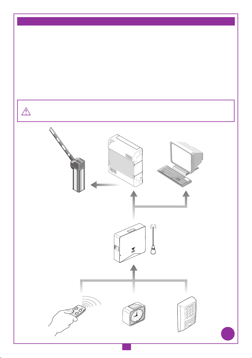
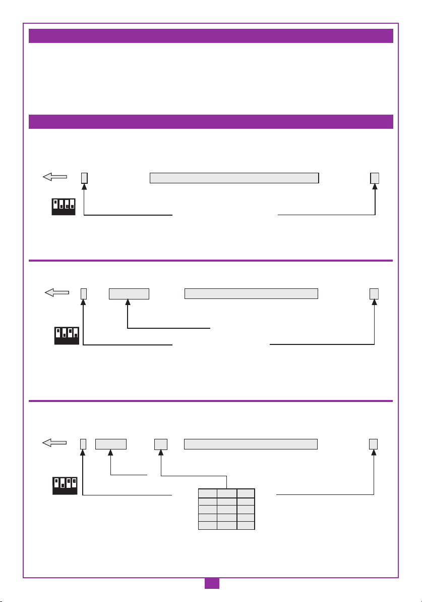
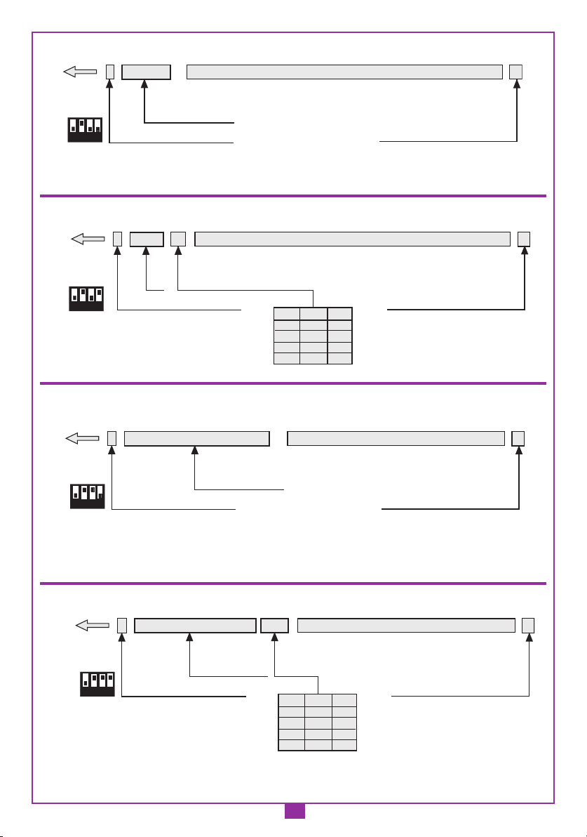
Descrizione
L'interfaccia RCQ486W00 è un dispositivo in grado di decodificare il segnale proveniente
o via radio da un trasmettitore Cardin mod. S486 oppure via filo da una tastiera numerica
Cardin mod. DKS250T, e di presentare ai morsetti d'uscita un segnale digitale in cui si trova
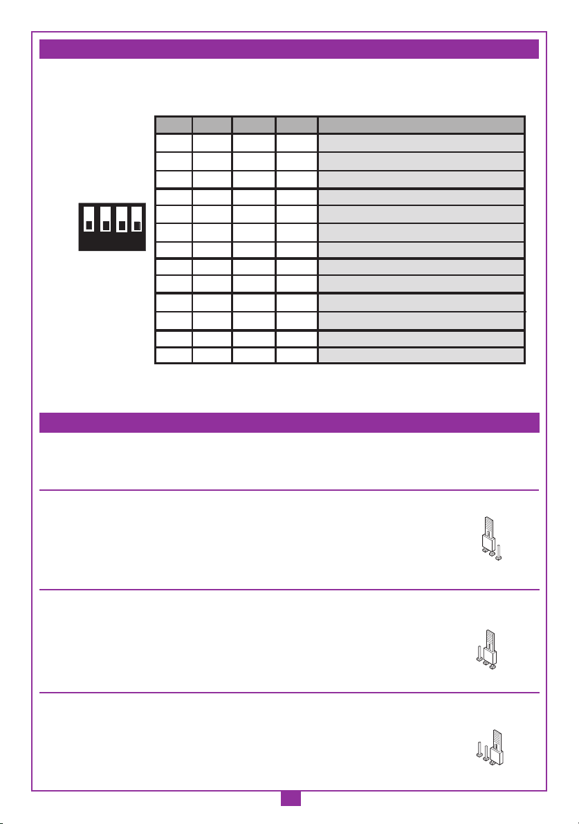
il codice del trasmettitore attivato, in 13 formati differenti, selezionabili tramite Dip-switch a
4 vie. I segnali d'uscita seguono le normative ISO-3554, relative alla codifica in formato ABA
Track (segnali RCP, RDP, CLS) oppure il protocollo WIEGAND (segnali DATA0 e DATA1 in
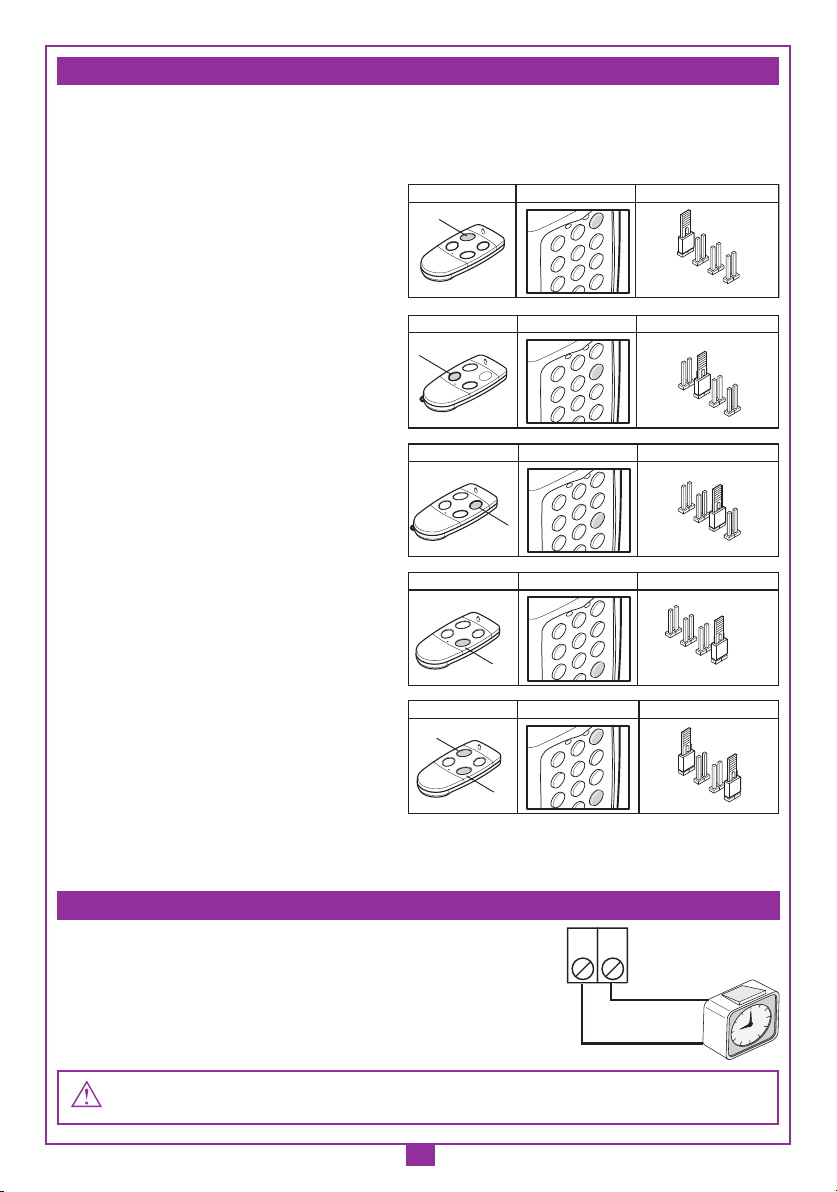
11 possibili configurazioni) o il protocollo SERIALE. È disponibile inoltre un contatto "EN" al
quale può essere collegato un temporizzatore oppure un interruttore con lo scopo di abilitare
o disabilitare l'interfaccia in diverse fascie orarie. L'uscita seriale RS232 (indipendentamente
dal protocollo selezionato) permette l'interfacciamento con un personal computer tramite
un software di gestione utente, fornito con il kit.
Il kit comprende:
- l'interfaccia RCQ486W00
- un cavo seriale RS232
- un CD Rom con il software di controllo
CARATTERISTICHE TECNICHE
Alimentazione ......................................................................................................................................................12/24Vac/dc
Assorbimento ................................................................................................................................................................45 mA
Massima portata via radio: 100 - 150 m. in spazio libero
Massima portata via filo con DKS250T: 150 m
Uscite : 5V - 12V - TTL Open Collector
Voh = 0.85 x Vdd: Vdd = 5V, Ioh = 1.2 mA max
Vdd = 12V, Ioh = 2.9 mA max
Vol = 0.4V, Iol = 15 mA max
RICEVITORE
- frequenza di ricezione ................................................................................868,3 MHz
- frequenza dell'oscillatore locale .................................................................857,6 MHz
- tolleranza dell'oscillatore locale ........................................ ±30 PPM da -20 a +75 °C
- emissione dell'oscillatore locale ................................................................. <-57 dBm
- sensibilità (per segnale a buon fine) .................................................-110 dBm 0,7 µV
- selettività ......................................................................................................... ±30 kHz
- modulazione ..........................................................................................................FSK
- modulazione con ΔF ....................................................................................... ≤20 kHz
- impedenza di ingresso antenna ...........................................................................50 Ω
- temperatura di esercizio .........................................................................-20°…+75 °C
ITALIANO AVVERTENZE ITALIANO
1
Dimensioni d'ingombro

3
In base alla tipologia e alle caratteristiche d’impianto individuare il punto di posa del sistema.
L'esempio di un accesso controllato sotto raffigurato può essere utile nella scelta dei compo-
nenti del sistema. Sebbene il modulo a radio frequenza (con caratteristiche tecniche descritte a
pagina 2) sia fornito con il kit si ricorda che almeno un radiocomando S486 oppure una tastiera
numerica DKS250T devono essere acquistati a parte con i seguenti codici:
TRQ486100 Trasmettitori tascabili 1 funzione
TRQ486200 Trasmettitori tascabili 2 funzioni
TRQ486300 Trasmettitori tascabili 3 funzioni
TRQ486400 Trasmettitori tascabili 4 funzioni
TRQ48640M Pulsantiera radio per fissaggio a muro 4 funzioni
DKS250T Tastiera numerica da esterno 4 funzioni
Attenzione! Questo libretto riporta istruzioni per uso, installazione e manutenzione
del solo ricevitore RCQ486W00. Per le istruzioni degli altri componenti del sistema
si consulti il libretto fornito con il prodotto.
CREAZIONE DI UN ACCESSO CONTROLLATO
2
CREAZIONE D'UN ACCESSO CONTROLLATO
INGRESSO
USCITA
RCQ449W00
13-01-02
DM0697 Description :
Product Code :
Date :
Drawing number :
P.J.Heath
CARDIN ELETTRONICA S.p.A - 31020 San Vendemiano (TV) Italy - via Raffaello, 36 Tel: 0438/401818 Fax: 0438/401831
Draft :
All rights reserved. Unauthorised copying or use of the information contained in this document is punishable by law
CONTROLLO ACCESSI
A
12
5
8
0
3
6
9
4
7
*
B
C
D
Barriera Controllo Accessi
RCQ449W00
RCQ486W00
ANS400
ANQ800-1
P.C.
S449-S486 Temporizzatore DKS250T

4
L’interfaccia dovrà essere collocata:
- in ambiente interno (in contenitore stagno se installata all'esterno)
- al riparo da urti e manomissioni;
- in una posizione facilmente raggiungibile dal tecnico, per interventi di manutenzione.
Fissaggio:
• Svitare le due viti di fissaggio e alzare il coperchio
• Tracciare (con l'ausilio della scatola) i due punti di fissaggio e fissare il contenitore utilizzando
due viti autofilettanti M4 e relativi Fischer (non di nostra fornitura)
• Togliere le due protezioni in plastica sull'ingresso dei cavi.
Collegamento elettrico
Attenzione! Alimentare l'interfaccia esclusivamente con un alimentatore di sicurezza.
L'utilizzo di alimentatori non di sicurezza può provocare pericolo.
L'interfaccia (circuito stampato CS1151B) è dotata di contenitore da interno e di morsettiera
a 12 vie con collegamento elettrico:
12V ac/dc tra i morsetti 3-4
24V ac/dc tra i morsetti 3-5
INSTALLAZIONE DELL'INTERFACCIA MULTIPROTOCOLLO RCQ486W00
3
CS1151B DC0365
12345678910
12V
0 24V
11 12
RF MODULE 433 MHz in FM
J2
J3
J4
J5
1
S1
23
ON
4
J2
J3
J4
J5
J1
J6
J6
123
Pos.1
123
Pos.2
J1 J2-J3-J4-J5
Pos.2
Pos.1
RS232
CON1
A
B
C
D
DATA0 / RCP
CLS / AUX
GND
EN
123
Pos.3
DATA1 / RDP
27-09-2003
DC0365 Description :
Product Code :
Date :
Drawing number :
P.J.Heath
CARDIN ELETTRONICA S.p.A - 31020 San Vendemiano (TV) Italy - via Raffaello, 36 Tel: 0438/401818 Fax: 0438/401831
Draft :
All rights reserved. Unauthorised copying or use of the information contained in this document is punishable by law
RCQ449W00 WIEGAND

5
Qualora sia prevista l'installazione di una tastiera numerica procedere come segue:
1) Far passare i cavi di collegamento "1"
provenienti dall'interfaccia attraverso il muro.
2) Forare il muro alla distanza indicata
in figura 4a (58 mm).
3) Inserire i Fischer "2" forniti con il kit.
4) Bloccare la contropiastra "3" utilizzando le
viti "4" fornite con il kit.
5) Collegare i faston dei cavi "1" ai faston della
tastiera "5" (fig, 4a-4b):
- filo rosso dal tastierino al morsetto 12 del interfaccia
- filo nero dal tastierino al morsetto 11 del interfaccia
6) Infine posizionare la tastiera (fig 4b-4c) e bloccarla
alla contropiastra utilizzando la vite speciale "S1"
e l'apposito attrezzo "K1".
COLLEGAMENTO TASTIERA ESTERNA DKS250T
A
12
5
8
0
3
6
9
4
7
*
B
C
D
Montaggio Tastiera DKS250T a superfice
DKS250T
28-11-2001
DM0557 Description :
Product Code :
Date :
Drawing number :
P.J.Heath
CARDIN ELETTRONICA S.p.A - 31020 San Vendemiano (TV) Italy - via Raffaello, 36 Tel: 0438/401818 Fax: 0438/401831
Draft :
All rights reserved. Unauthorised copying or use of the information contained in this document is punishable by law
58 mm
1
23
4
5
Montaggio Tastiera DKS250T a superfice
DKS250T
04-03-2002
DM0670 Description :
Product Code :
Date :
Drawing number :
P.J.Heath
CARDIN ELETTRONICA S.p.A - 31020 San Vendemiano (TV) Italy - via Raffaello, 36 Tel: 0438/401818 Fax: 0438/401831
Draft :
All rights reserved. Unauthorised copying or use of the information contained in this document is punishable by law
F
S
1
(
-
)
B
l
F
S
2
(
+
)
R
d
FASTON
A
12
5
8
0
3
6
9
4
7
*
B
C
D
Montaggio Tastiera DKS250T a superfice
DKS250T
28-11-2001
DM0669 Description :
Product Code :
Date :
Drawing number :
P.J.Heath
CARDIN ELETTRONICA S.p.A - 31020 San Vendemiano (TV) Italy - via Raffaello, 36 Tel: 0438/401818 Fax: 0438/401831
Draft :
All rights reserved. Unauthorised copying or use of the information contained in this document is punishable by law
K1
S1
4a
4b
4c

6
T
1 Digitare sulla tastiera il codice numerico utente
e premere conferma "
*
"
2 La tastiera emette un beep per 2 secondi
+ LED verde acceso
3 Premere A-B-C o D nella colonna a destra sulla tastiera (Es. "C")
Attivazione avvenuta!
4 Dopo 5 secondi di inattività verrà emesso un beep.
Il LED verde si spegne e si esce dalla modalità.
Qualora sia previsto l'uso di radiocomandi, l'installazione dell'antenna diventa fondamentale;
infatti collegata al ricevitore rappresenta il punto di ricezione del radiocomando. È necessa-
rio collegare al ricevitore l'antenna ANQ800-1 accordata mediante cavetto coassiale RG58
(impedenza 50Ω) di lunghezza max. 15m; l'antenna va posizionata all'esterno nel punto più
elevato e visibile, lontano da strutture metalliche.
• Collegare la massa dell'antenna al morsetto "1" ed il polo al morsetto "2".
Attenzione: La scelta deve essere effettuata tra le possibilità "WIEGAND, ISO2 o
SERIALE". Non è possibile utilizzare più protocolli contemporaneamente.
Protocollo WIEGAND o SERIALE
Il collegamento fisico tra il controllo accessi e l'inter-
faccia RCQ486W00 si effettua tra i morsetti:
6 (DATA 0), 7 (DATA 1) e 9 ( GND)
Protocollo ISO2 (magnetic stripe)
Il collegamento fisico tra il controllo accessi e l'inter-
faccia RCQ486W00 si effettua tra i morsetti 6 (RCP,
"read clock pulse"),
7 (RDP, "read data pulse"), 8 (CLS,
"card loading signal") e 9 (GND)
6 7 8 9
DATA 0 GND
DATA 1
6 7 8 9
RCP GND
RDP CLS
COLLEGAMENTO AL DISPOSITIVO DI CONTROLLO ACCESSI
COLLEGAMENTO ANTENNA ESTERNA ANQ800-1
*
8
0
9
4
7
*D
123
6B
C
ON
ATTIVAZIONE CODICE UTENTE
DKS250T
c
1
5
8
6
9
4
B
C

7
L'interfaccia dispone di 13 formati differenti per comunicare con una centrale di controllo
accessi. Sono disponibili 11 formati WIEGAND, un formato ISO 2, ed un formato SERIALE
selezionabili tramite il Dip-Switch "S1".
Per una spiegazione dettagliata della sequenza di bit inviata nei vari formati consultare
pagine 9-13.
Sono disponibili tre modalità per la tensione dei segnali in uscita nei formati WIEGAND,
ISO2 e SERIALE:
1) 12Vdc in uscita con jumper "J6" in posizione "1"
2) 5Vdc in uscita con jumper "J6" in posizione "2"
3) TTL Open collector in uscita con jumper "J6" in posizione "3"
(contatto aperto)
SELEZIONE DELLA TENSIONE DI USCITA
Pos. 1
1 2 3
J6
Pos. 2
1 2 3
J6
Pos. 3
1 2 3
J6
SELEZIONE DEL PROTOCOLLO DI USCITA
DIP1 DIP2 DIP3 DIP4 PROTOCOL
ON OFF OFF OFF WIEGAND 26 BIT
ON OFF ON OFF WIEGAND 26 BIT SITE
ON OFF ON ON WIEGAND 26 BIT SITE + CH
OFF ON OFF OFF WIEGAND 37 BIT
OFF ON OFF ON WIEGAND 37 BIT + CH
OFF ON ON OFF WIEGAND 37 BIT SITE
OFF ON ON ON WIEGAND 37 BIT SITE + CH
OFF OFF ON OFF WIEGAND 37 BIT D10302
OFF OFF ON ON WIEGAND 37 BIT D10302 (BCD)
ON ON OFF OFF WIEGAND 50 BIT
ON ON OFF ON WIEGAND 50 BIT + CH
OFF OFF OFF ON ISO 2
ON ON ON ON SERIAL
1
S1
23
ON
4

8
Per abilitare/disabilitare l'attivazione dell'uscita in formato WIEGAND, ISO2 o SERIALE
inserire i jumper "J2","J3","J4","J5" come segue:
1) Con il jumper "J2" inserito, il canale "A"
del trasmettitore S486 o della tastiera
DKS250T attiva la funzione "A" del rice-
vitore RCQ486W00. Tutti gli altri canali
sono disabilitati.
2) Con il jumper "J3" inserito, il canale "B"
del trasmettitore S486 o della tastiera
DKS250T attiva la funzione "B" del rice-
vitore RCQ486W00. Tutti gli altri canali
sono disabilitati.
3) Con il jumper "J4" inserito, il canale "C"
del trasmettitore S486 o della tastiera
DKS250T attiva la funzione "C" del rice-
vitore RCQ486W00. Tutti gli altri canali
sono disabilitati.
4) Con il jumper "J5" inserito, il canale "D"
del trasmettitore S486 o della tastiera
DKS250T attiva la funzione "D" del rice-
vitore RCQ486W00. Tutti gli altri canali
sono disabilitati.
5) Con i jumper "J2" e J5" inseriti, i canali
"A" e "D" del trasmettitore S486 o della
tastiera DKS250T attiveranno rispettiva-
mente le funzioni "A" e "D" del ricevitore
RCQ486W00.
Tutti gli altri canali sono disabilitati.
Sono possibili tutte le combinazioni fino ad un massimo di 4 tasti di canale.
Collegando un timer oppure un interruttore semplice
tra i morsetti 9 e 10 si ha la possibilità di abilitare o disabilitare
l'interfaccia in diverse fascie orarie. Esempio: se nessuno deve
entrare nella zona o stabilimento controllato dopo le dieci di sera
basta impostare il temporizzatore in maniera che apra il contatto
"EN" dopo tale ora.
Attenzione: Se non si collega nessun dispositivo tra i morsetti 9 e 10 il contatto deve essere ponti-
cellato. L'interfaccia non attiva l'uscita WIEGAND/ISO2/SERIALE con questo contatto aperto.
ABILITAZIONE DI CANALI RADIOCOMANDO/TASTIERA
CH A
A
12
5
8
3
6
9
4
B
C
D
J2
J3
J4
J5
TX S449 - S486 DKS250
RCQ449W00 - RCQ486W00
ABCD
CH B
A
12
5
8
3
6
9
4
B
C
D
J3
TX S449 - S486 DKS250
RCQ449W00 - RCQ486W00
B
TX S449 -S486 DKS250
RCQ449W00 - RCQ486W00
CH C
A
12
5
8
3
6
9
4
B
C
D
J4
C
CH D
A
12
5
8
3
6
9
4
B
C
D
J5
TX S449 - S486 DKS250
RCQ449W00 - RCQ486W00
D
CH D
A
12
5
8
3
6
9
4
B
C
D
J5
TX S449 - S486 DKS250
RCQ449W00 - RCQ486W00
J2
CH A
AD
ABILITAZIONE CON TEMPORIZZATORE
9 10
GND
EN

9
Collegando un personal computer al ricevitore RCQ486W00 tramite l'interfaccia RS232 ed
installando il software di gestione fornito su CD Rom ( il cavo ed il CD Rom sono forniti con
il kit) si può ottenere un elenco degli eventi (ossia le entrate ed uscite giornaliere del sistema).
Per una spiegazione dettagliata del software si consulti il manuale d'istruzione registrato in
formato PDF sul CD Rom stesso.
Nota 1: Nella sequenza dei bit inviati in uscita, il primo ad essere trasmesso è il bit 1
1) WIEGAND 26 bit
Attenzione! Il codice è limitato a 16’777’215. Per utilizzare codici con numero più grande,
consultare a pagina 14 il paragrafo "Troncamento del codice"
2) WIEGAND 26 bit con codice SITO
Attenzione! Il codice è limitato a 65’535. Per utilizzare codici con numero più grande, con-
sultare a pagina 14 il paragrafo "Troncamento del codice"
3) WIEGAND 26 bit con codice SITO + informazione di canale
Attenzione! Il codice è limitato a 65’535. Per utilizzare codici con numero più grande, con-
sultare a pagina 14 il paragrafo "Troncamento del codice"
SOFTWARE DI INTERFACCIA SU PC
PROTOCOLLO WIEGAND (SEQUENZE DI BIT)
1 2 3 4 5 6 7 8 9 10 11 12 13 14 15 16 17 18 19 20 21 22 23 24 25 26
Bit di "parità pari" dei bit 2-13 Bit di "parità dispari" dei bit 14-25
codice in binario (10 msb, 25 lsb)
1
S1
23
ON
4
= "000001"
bit 8 bit 9 CH
0 0 A
0 1 B
1 0 C
1 1 D
Informazione di canale
1 2 3 4 5 6 7 8 9 10 11 12 13 14 15 16 17 18 19 20 21 22 23 24 25 26
Bit di "parità pari" dei bit 2-13 Bit di "parità dispari" dei bit 14-25
codice in binario (2 msb, 25 lsb)
1
S1
23
ON
4
1 2 3 4 5 6 7 8 9 10 11 12 13 14 15 16 17 18 19 20 21 22 23 24 25 26
Bit di "parità pari" dei bit 2-13 Bit di "parità dispari" dei bit 14-25
codice in binario (10 msb, 25 lsb)
1
S1
23
ON
4
codice di sito = "00000001"

10
4) WIEGAND 37 bit
5) WIEGAND 37 bit + informazione di canale
6) WIEGAND 37 bit con codice SITO
Attenzione! Il codice è limitato a 524’287. Per utilizzare codici con numero più grande,
consultare a pagina 14 il paragrafo "Troncamento del codice"
7) WIEGAND 37 bit con codice SITO + informazione di canale
Attenzione! Il codice è limitato a 524’287. Per utilizzare codici con numero più grande,
consultare a pagina 14 il paragrafo "Troncamento del codice"
1 2 3 4 5 6 7 8 9 10 11 12 13 14 15 16 17 18 19 20 21 22 23 24 25 26 27 28 29 30 31 32 33 34 35 36 37
Bit di "parità pari" dei bit 2-18 Bit di "parità dispari" dei bit 18-36
"0"
codice di uscita in binario, 9 (msb), 36 (lsb)
I bit "2"…"8" sono sempre nulli
1
S1
23
ON
4
1 2 3 4 5 6 7 8 9 10 11 12 13 14 15 16 17 18 19 20 21 22 23 24 25 26 27 28 29 30 31 32 33 34 35 36 37
Bit di "parità pari" dei bit 2-18 Bit di "parità dispari" dei bit 18-36
"0" Informazione di canale
bit 7 bit 8 CH
0 0 A
0 1 B
1 0 C
1 1 D
codice di uscita in binario, 9 (msb), 36 (lsb)
I bit "2"…"6" sono sempre nulli
1
S1
23
ON
4
1 2 3 4 5 6 7 8 9 10 11 12 13 14 15 16 17 18 19 20 21 22 23 24 25 26 27 28 29 30 31 32 33 34 35 36 37
Bit di "parità pari" dei bit 2-18 Bit di "parità dispari" dei bit 18-36
= "000000000000001"
codice di uscita in binario, 18 (msb), 36 (lsb)
1
S1
23
ON
4
1 2 3 4 5 6 7 8 9 10 11 12 13 14 15 16 17 18 19 20 21 22 23 24 25 26 27 28 29 30 31 32 33 34 35 36 37
Bit di "parità pari" dei bit 2-18 Bit di "parità dispari" dei bit 18-36
= "0000000000001"
codice di uscita in binario, 18 (msb), 36 (lsb)
1
S1
23
ON
4
Informazione
di canale
bit 16 bit 17 CH
0 0 A
0 1 B
1 0 C
1 1 D

11
8) WIEGAND 37 bit D10302
9) WIEGAND 37 bit D10302 (BCD)
Attenzione! Il codice è limitato a 99’999’999. Per utilizzare codici con numero più grande,
consultare a pagina 14 il paragrafo "Troncamento del codice"
10) WIEGAND 50 bit
11) WIEGAND 50 bit + informazione di canale
1 2 3 4 5 6 7 8 9 10 11 12 13 14 15 16 17 18 19 20 21 22 23 24 25 26 27 28 29 30 31 32 33 34 35 36 37
Bit di "parità pari" dei bit 2-18 Bit di "parità dispari" dei bit 18-36
= "1010000"
codice di uscita in binario, 9 (msb), 36 (lsb)
1
S1
23
ON
4
1 2 3 4 5 6 7 8 9 10 11 12 13 14 15 16 17 18 19 20 21 22 23 24 25 26 27 28 29 30 31 32 33 34 35 36 37
Bit di "parità pari" dei bit 2-18 Bit di "parità dispari" dei bit 18-36
= "101"
codice di uscita in BCD (5-8 cifra più significativa, 33-36 cifra meno significativa)
1
S1
23
ON
4
1 2 3 4 5 6 7 8 9 10 11 12 13 14 15 16 17 18 19 20 21 22 23 24 25 26 27 28 29 30 31 32 33 34 35 36 37 38 39 40 41 42 43 44 45 46 47 48 49 50
Bit di "parità pari" dei bit 2-25 Bit di "parità dispari" dei bit 26-49
"0"
codice di uscita in binario, 22 (msb), 49 (lsb)
1
S1
23
ON
4
"1" "0"
1 2 3 4 5 6 7 8 9 10 11 12 13 14 15 16 17 18 19 20 21 22 23 24 25 26 27 28 29 30 31 32 33 34 35 36 37 38 39 40 41 42 43 44 45 46 47 48 49 50
Bit di "parità pari" dei bit 2-25 Bit di "parità dispari" dei bit 26-49
"0" Informazione di canale
bit 48 bit 49 CH
0 0 A
0 1 B
1 0 C
1 1 D
codice di uscita in binario, 20 (msb), 47 (lsb)
1
S1
23
ON
4
"1" "0"

12
Diagrammi temporali dei segnali WIEGAND
La trama in formato WIEGAND viene emessa attraverso i segnali DATA0 e DATA1. La durata
del singolo bit è di 50µs mentre l’attesa tra un bit ed il successivo è di 2ms.
La trama che esce dall'interfaccia è formata da 16
caratteri. Ogni carattere è costituito da 5 bit secondo la
codifica della tabella, dove il bit più significativo è B4, il
meno significativo è B1.
Il bit di parità è la parità dispari di B4, B3, B2, B1.
La trama è la seguente: START + CANALE (1 carattere) +
SEP + CODICE (10 caratteri) + SEP + END + LRC, cioè 16
caratteri in totale.
Esempio di costruzione trama limitata a 6 caratteri: trasmissione del codice "452"
Alla fine della trama viene inviato il carattere di controllo
LRC, che viene calcolato facendo la parità pari in senso
longitudinale (sulle colonne) dei corrispondenti bit come si
vede nella tabella.
Il primo bit ad uscire è B1 e l’ultimo è quello di parità.
Diagrammi temporali dei segnali ISO2
I segnali ISO2 sono 3: CLS (Card Loading Signal), RCP (Read Clock Pulse) e RDP (Read
Data Pulse). I 3 segnali sono attivi bassi.
Prima di tutto si abbassa CLS e dopo 5ms si inviano 10 “colpi” di clock; poi si invia il pac-
chetto di dati e alla fine si attendono 5ms prima di alzare CLS.
PROTOCOLLO ISO2 (SEQUENZE DI BIT)
Parità B4 B3 B2 B1 Carattere
1 0 0 0 0 0
0 0 0 0 1 1
0 0 0 1 0 2
1 0 0 1 1 3
0 0 1 0 0 4
1 0 1 0 1 5
1 0 1 1 0 6
0 0 1 1 1 7
0 1 0 0 0 8
1 1 0 0 1 9
0 1 0 1 1 START
0 1 1 0 1 SEP
0 1 1 1 1 END
CLS
5ms
RCP
RDP
5ms
SIGNIFICATO BIT PARITÁ
Start 1 0 1 1 0
"4" 0 1 0 0 0
"5" 0 1 0 1 1
"2" 0 0 1 1 0
End 1 1 1 1 1
LRC 0 1 1 1 0
101
DATA 1
2mS
50µS
DATA 0

13
Il periodo (Tp) ha una durata di 1ms ed è così costituito:
400µs in cui le linee RDP (dati) e RCP (clock) sono alte
300µs in cui la linea RDP è bassa se il bit vale 1 (RCP è sempre alto)
300µs (Tck) in cui la linea RCP è bassa (RDP mantiene il livello che aveva prima)
Alla fine del periodo, RCP e RDP tornano al livello alto.
Tck = 300µs
Td = 600µs
Tp = 1ms
Il protocollo seriale presenta all'uscita del morsetto DATA0 il protocollo standard RS232
(baudrate = 9600, senza parità, 8 bit, e un bit di stop) nel seguente formato:
00C000B1B2B3B4B50
dove 0 è il carattere ASCII "0" (30h), B1B2B3B4B5 sono le 5 cifre meno significative del
codice in esadecimale e "C" rappresenta il canale trasmesso seconda la tabella:
L'uscita DATA1 viene attivata 200ms prima di inviare i dati sull'uscita DATA0 nel seguente
modo:
101
RCP
Tck
Td
RDP
Tp
PROTOCOLLO SERIALE (SEQUENZE DI BIT)
CANALE CAR
A 1 (31h)
B 2 (32h)
C 4 (34h)
D 8 (38h)
DATA1
200ms
DATA0

14
Scegliendo il protocollo WIEGAND 1,2,3,6,7 e 9 (pagine 9-11) è possibile che il codice del
trasmettitore S486 sia superiore al massimo codice rappresentabile con i bit a disposizione.
Con jumper "J1" disinserito, nessuna uscita WIEGAND sarà attivata, mentre sarà disponibile
sull'uscita RS232 l'informazione sul codice ricevuto.
Inserendo il jumper "J1" si attiva la funzione "troncamento codice", che provvederà ad
eliminare i bit più significativi non rappresentabili nel formato WIEGAND selezionato.
Es 1:
Se si seleziona il protocollo WIEGAND 26 bit con codice SITO (limite 65’535) ed il codice
del trasmettitore è 356’890, la funzione di troncamento cancellerà la prima cifra e il codice
che verrà inviato in uscita WIEGAND sarà dunque 56’980 (numero minore di 65’535).
Es 2:
Se si seleziona il protocollo WIEGAND 37 bit con codice SITO (limite 542’287) ed il codice
del trasmettitore è 18’436’500, la funzione di troncamento restituirà il codice 436’500.
Attenzione! Attivando la funzione di "Troncamento codice" (jumper "J1" chiuso)
è possibile che due trasmettitori, pur con codice diverso, attivino all'uscita dell'in-
terfaccia una sequenza di bit identica.
Ad esempio, nel caso del formato WIEGAND 26 bit con codice SITO i codici 138’612
e 238’612 attivano in uscita la stessa sequenza di bit: 38’612.
TRONCAMENTO DEL CODICE

15
RADIO RENO S449
Dimensioni di ingombro
RXPR RENO
11-06-01
DM0538 Description :
Product Code :
Date :
Drawing number :
P.J.Heath
CARDIN ELETTRONICA S.p.A - 31020 San Vendemiano (TV) Italy - via Raffaello, 36 Tel: 0438/401818 Fax: 0438/401831
Draft :
All rights reserved. Unauthorised copying or use of the information contained in this document is punishable by law
85
20
120
Before commencing with the installation of this appliance make sure that you have read the following instruc-
tions carefully. The use and installation of these appliances must rigorously respect the indications supplied by
the manufacturer. The manufacturer accepts no liability for damage caused by, or situations arising from, the
improper use of these appliances. These instructions are aimed at professionally qualified "installers of electrical
equipment" and must respect the local standards and regulations in force.
Description
The RCQ486W00 interface is a device which is able to decode a radio frequency signal coming
from a Cardin S486 transmitter or via cable coming from the Cardin numerical keyboard DKS250T.
Once decoded this signal is converted into a digital frame containing the transmitter code it is
sent to the output in 13 different formats which can be selected by means of a four-way Dip-
switch. The output signals follow the ISO-3554 standard encoded in ABA track (RCP, RDP,
CLS signals), the WIEGAND protocol (Datao and Data1 signals in 11 possible configurations)
or the SERIAL protocol. The interface also has an enable contact "EN" which can be wired to
a timer or a normal switch allowing you to activate or deactivate the interface in different time
bands. The RS232 serial interface (despite which protocol you have selected) allows you to
connect the device to a personal computer using software supplied with the kit.
The kit contains the following:
- the interface RCQ486W00
- a serial cable RS232
- a CD Rom containing the management software
TECHNICAL SPECIFICATIONS
Power supply ..................................................................................................................................................... 12/24Vac-dc
Power consumption .....................................................................................................................................................45 mA
Maximum range via radio: 100 - 150 m. in open space
Maximum range via cable using the DKS250T: 150 m
Outputs : 5V - 12V - TTL Open Collector
Voh = 0.85 x Vdd: Vdd = 5V, Ioh = 1.2 mA max.
Vdd = 12V, Ioh = 2.9 mA max.
Vol = 0.4V, Iol = 15 mA max
RECEIVER
- reception frequency ...................................................................................868,3 MHz
- local oscillation frequency ..........................................................................857,6 MHz
- local oscillation tolerance .............................................± 30 PPM from -20 to +75 °C
- local oscillation emission ............................................................................ <-57 dBm
- sensitivity (for a fine signal) ..............................................................-110 dBm 0,7 µV
- selectivity ........................................................................................................ ±30 kHz
- modulation .............................................................................................................FSK
- modulation with ΔF ......................................................................................... ≤20 kHz
- Antenna impedance .............................................................................................50 Ω
- Operating temperature ...........................................................................-20°…+75 °C
ENGLISH REMARKS ENGLISH
Overall dimensions
1

16
2
CREATING AN ACCESS CONTROL SYSTEM
RADIO RENO S449
INPUT
OUTPUT
Programmazione Radio Reno
RXPR RENO
20-07-01
DM0681 Description :
Product Code :
Date :
Drawing number :
P.J.Heath
CARDIN ELETTRONICA S.p.A - 31020 San Vendemiano (TV) Italy - via Raffaello, 36 Tel: 0438/401818 Fax: 0438/401831
Draft :
All rights reserved. Unauthorised copying or use of the information contained in this document is punishable by law
ACCESS CONTROL
A
12
5
8
0
3
6
9
4
7
*
B
C
D
Barrier Access Control
RCQ449W00
RCQ486W00
ANS400
ANQ800-1
P.C.
S449 - S486 Timer DKS250T
According to the type and characteristics of the system work out where it will be installed. The
access control system example shown below could be useful when choosing the individual
components that will make up the system. Although the receiver module (technical specifica-
tions on page 15) is included in the DKS250T kit you must separately acquire at least one
S486 transmitter or a numerical code keyboard from the following list:
TRQ486100 Pocket transmitters 1 function
TRQ486200 Pocket transmitters 2 functions
TRQ486300 Pocket transmitters 3 functions
TRQ486400 Pocket transmitters 4 functions
TRQ48640M Wall mounted transmitter 4 functions
DKS250T Numerical all-weather keyboard 4 functions
Attention! This manual contains user, installation and maintenance instructions for
the RCQ486W00 interface. For instructions regarding other components making up
the system consult the manuals supplied with the products.

17
The interface site must be:
- indoors (or stored in a waterproof container if installed outdoors)
- a position safe from accidental collision;
- in a position which the technician can easily reach.
Fastening:
• Remove the two holding screws and lift up the cover
• Using the container as a template mark the four points at which the fastening holes are to
be drilled and fasten down using four self-tapping M4 screws and relative rawlplugs (not
supplied with the kit).
• Remove the two plastic cable dividers.
Electrical connection
Warning! The receivers must only be powered by a safety power pack. The use of non safety
power packs could provoke damage to the system.
The interface (printed circuit CS1151B) is fitted with an indoor container and has a 12-way
terminal board with the following electrical connection:
12V ac/dc between binding posts 3-4
24V ac/dc between binding posts 3-5
INSTALLING THE RCQ486W00 MULTIPROTOCOL INTERFACE
CS1151B DC0365
12345678910
12V
0 24V
11 12
RF MODULE 433 MHz in FM
J2
J3
J4
J5
1
S1
23
ON
4
J2
J3
J4
J5
J1
J6
J6
123
Pos.1
123
Pos.2
J1 J2-J3-J4-J5
Pos.2
Pos.1
RS232
CON1
A
B
C
D
DATA0 / RCP
CLS / AUX
GND
EN
123
Pos.3
DATA1 / RDP
27-09-2003
DC0365 Description :
Product Code :
Date :
Drawing number :
P.J.Heath
CARDIN ELETTRONICA S.p.A - 31020 San Vendemiano (TV) Italy - via Raffaello, 36 Tel: 0438/401818 Fax: 0438/401831
Draft :
All rights reserved. Unauthorised copying or use of the information contained in this document is punishable by law
RCQ449W00 WIEGAND

18
If you have decided to install a keyboard proceed as follows:
1) Pass the connecting cables,
"1" coming from the interface,
through the wall.
2) Drill the wall at the distance indicated
in figure 4a (58 mm).
3) Insert the rawlplugs "2" supplied with the kit.
4) Fasten down the counter plate "3" using the
screws "4" supplied with the kit.
5) Connect the Fastons on the wires "1" to the Fastons
on the keyboard "5" (fig, 4a-4b):
- the red wire of the keyboard connects to
binding post 12 on the interface card
- the black wire of the keyboard connects to
binding post 11 on the interface card
6) Position the keyboard (fig 4b-4c) and fasten it down to
the counter plate using the special screw "S1"
and the tool "K1".
CONNECTING THE ALL-WEATHER NUMERICAL KEYBOARD DKS250T
A
12
5
8
0
3
6
9
4
7
*
B
C
D
Montaggio Tastiera DKS250T a superfice
DKS250T
28-11-2001
DM0557 Description :
Product Code :
Date :
Drawing number :
P.J.Heath
CARDIN ELETTRONICA S.p.A - 31020 San Vendemiano (TV) Italy - via Raffaello, 36 Tel: 0438/401818 Fax: 0438/401831
Draft :
All rights reserved. Unauthorised copying or use of the information contained in this document is punishable by law
58 mm
1
23
4
5
Montaggio Tastiera DKS250T a superfice
DKS250T
04-03-2002
DM0670 Description :
Product Code :
Date :
Drawing number :
P.J.Heath
CARDIN ELETTRONICA S.p.A - 31020 San Vendemiano (TV) Italy - via Raffaello, 36 Tel: 0438/401818 Fax: 0438/401831
Draft :
All rights reserved. Unauthorised copying or use of the information contained in this document is punishable by law
F
S
1
(
-
)
B
l
F
S
2
(
+
)
R
d
FASTON
A
12
5
8
0
3
6
9
4
7
*
B
C
D
Montaggio Tastiera DKS250T a superfice
DKS250T
28-11-2001
DM0669 Description :
Product Code :
Date :
Drawing number :
P.J.Heath
CARDIN ELETTRONICA S.p.A - 31020 San Vendemiano (TV) Italy - via Raffaello, 36 Tel: 0438/401818 Fax: 0438/401831
Draft :
All rights reserved. Unauthorised copying or use of the information contained in this document is punishable by law
K1
S1
4a
4b
4c

19
1 Type in the numerical user code on the keyboard
and press confirm "
*
"
2 The keyboard will emit a beep for 2 seconds
and the green LED will light up.
3 Press A-B-C or D in the right-hand column of the keyboard (e.g. "C")
Activation has been carried out!
4 After 5 seconds of inactivity a beep will sound.
The green LED will switch off and you will quit the user code mode.
If you have decided to use transmitters the installation of the antenna is fundamental: In fact
connected to the receiver it represents the reception point for the transmitter. An ANQ800-1
tuned antenna using a coaxial cable RG58 (impedance 50Ω) with a maximum length of 15m
must be installed. The antenna should be positioned out of doors in the highest possible
point, visible and away from metal structures.
• Connect the antenna mass to binding post "1" and the antenna pole to binding post "2"
Attention: You must choose between "WIEGAND, ISO2 and SERIAL".
Two different protocols cannot be used contemporaneously
WIEGAND or SERIAL protocol
The physical connection between the access control
device and the RCQ486W00 interface is carried out
at the following binding posts:
6 (DATA 0), 7 (DATA 1) and 9 ( GND)
ISO2 protocol (magnetic stripe)
The physical connection between the access control
device and the RCQ486W00 interface is carried out
at the following binding posts: 6 (RCP, "read clock
pulse"), 7 (RDP, "read data pulse"), 8 (CLS, "card
loading signal") and 9 (GND)
CONNECTING THE EXTERNAL ANTENNA ANQ800-1
CONNECTING TO AN ACCESS CONTROL DEVICE
6 7 8 9
DATA 0 GND
DATA 1
6 7 8 9
RCP GND
RDP CLS
*
8
0
9
4
7
*D
123
6B
C
ON
c
1
5
8
6
9
4
B
C
ACTIVATING A USER CODE DKS250T

20
The interface has thirteen different formats for communicating with the access control device.
11 of these formats are WIEGAND, one is ISO2 and the other is SERIAL and they can be
selected using the dip-switch "S1".
For a detailed description of the bit transmission sequence consult pages 21 to 23.
There are three different methods for choosing the output voltage for the formats WIEGAND,
ISO2 and SERIAL.
1) 12Vdc output with jumper "J6" in position "1"
2) 5Vdc output with jumper "J6" in position "2"
3) TTL Open collector output with jumper "J6" in position "3"
(open contact)
CHOOSING THE OUTPUT PROTOCOL
Pos. 1
1 2 3
J6
Pos. 2
1 2 3
J6
Pos. 3
1 2 3
J6
SELECTING THE OUTPUT VOLTAGE
DIP1 DIP2 DIP3 DIP4 PROTOCOL
ON OFF OFF OFF WIEGAND 26 BIT
ON OFF ON OFF WIEGAND 26 BIT SITE
ON OFF ON ON WIEGAND 26 BIT SITE + CH
OFF ON OFF OFF WIEGAND 37 BIT
OFF ON OFF ON WIEGAND 37 BIT + CH
OFF ON ON OFF WIEGAND 37 BIT SITE
OFF ON ON ON WIEGAND 37 BIT SITE + CH
OFF OFF ON OFF WIEGAND 37 BIT D10302
OFF OFF ON ON WIEGAND 37 BIT D10302 (BCD)
ON ON OFF OFF WIEGAND 50 BIT
ON ON OFF ON WIEGAND 50 BIT + CH
OFF OFF OFF ON ISO 2
ON ON ON ON SERIAL
1
S1
23
ON
4
Table of contents
Languages:
Popular Recording Equipment manuals by other brands

Sony
Sony Walkman PCM-M1 Service manual

Yamaha
Yamaha YRM-502 owner's manual

Meicheng
Meicheng DSS-R-CL1100 manual

QRS Music Technologies
QRS Music Technologies QRS PNO3 installation manual

Philips
Philips CDR-775 Instructions for use

Audio Technica
Audio Technica System 10 Stompbox ATW-1501 Installation and operation