Cardini RH9T150 User manual

234
5678
9 10 11
RANGEHOOD
INSTRUCTION MANUAL
Read this manual carefully before operation
Pictures in this manual are for reference only.
RH9T150

Contents
Recommendations and Suggestions..................... 3
01
02
03
04
05
07
08
Dimensions............................................................ 5
Components..........................................................
Use........................................................................ 8
Maintenance.......................................................
2
1
Troubleshooting..................................................
Contents.................................................................
06
Installation.............................................................
2
4
6
9
1
09 Warranty & Service............................................. 11

RECOMMENDATIONS AND SUGGESTIONS
The instructions for use apply to several versions of this appliance. Accordingly, you
may find descriptions of individual features that do not apply to your specific appliance.
INSTALLATION
The manufacturer will not be held liable for any damages resulting from incorrect or
improper installation.
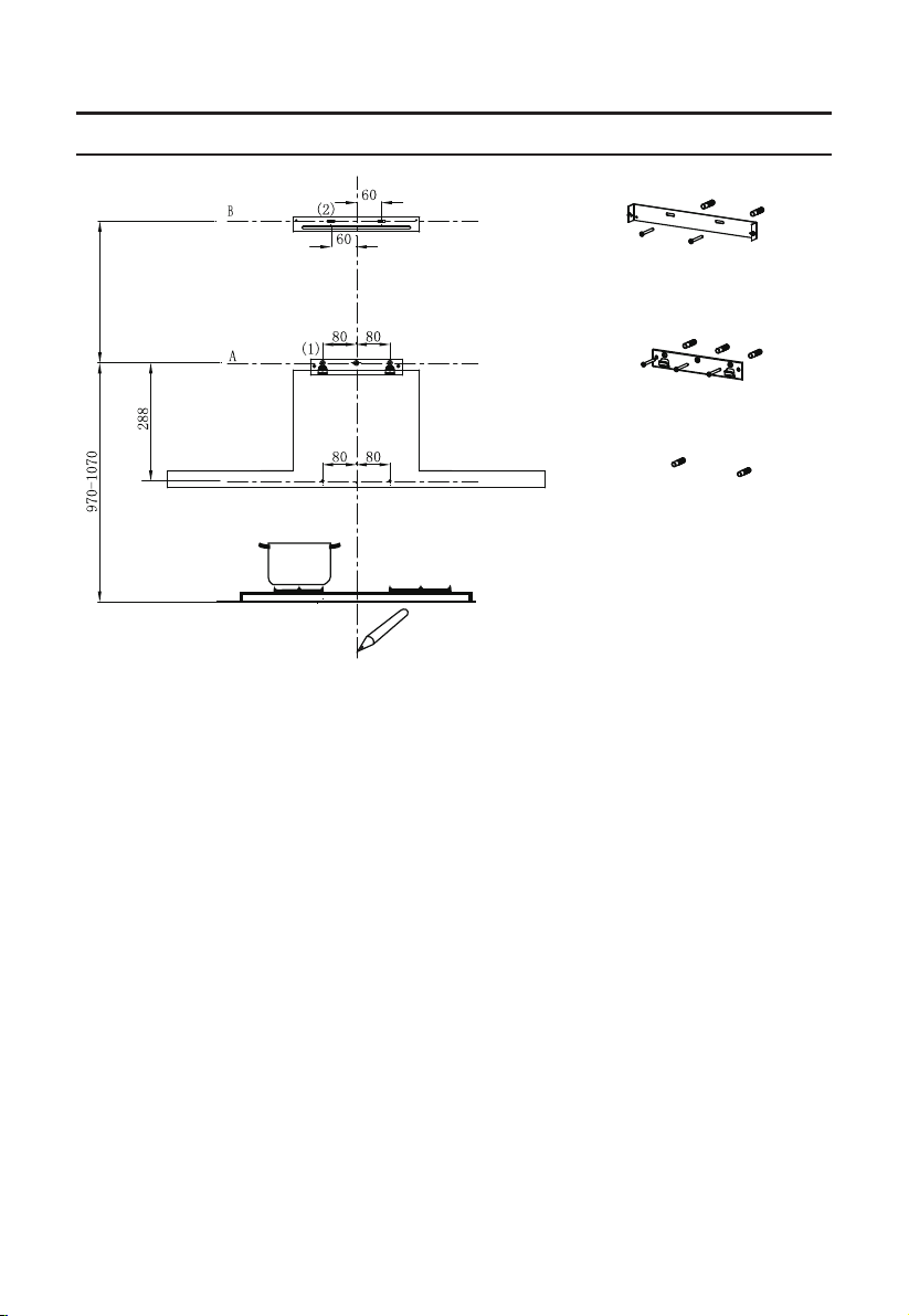
The minimum distance between the supporting surface for the cooking vessels on the
hob and the lowest part of the range hood. ( When the range hood is located above a
gas appliance, this distance shall be at least 65 cm. If the instructions for installation for
the gas hob specify a greater distance, this has to be taken into account. The distance of
65 cm can be reduced for:non-combustible parts of range hoods, and parts operating at
safety extra low voltage,Provided these parts do not give access to live parts if deformed ;)
Check that the mains voltage corresponds to that indicated on the rating plate fixed to
the hood.
For Class I appliances,check that the domestic power supply guarantees adequate earthing.
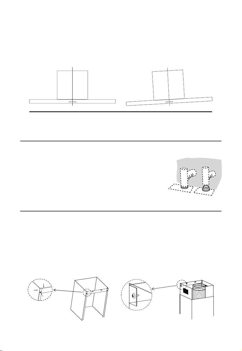
Connect the extractor to the exhaust flue through a pipe of minimum diameter 120mm.
The route of the flue must be as short as possible.
The air must not be discharged into a flue that is used for exhausting fumes from
appliances burning gas or other fuels.
If the extractor is used in conjunction with non-electrical appliances (e.g. gas burning
appliances),a sufficient degree of aeration must be guaranteed in the room in order to
prevent the backflow of exhaust gas. The kitchen must have an opening communicating
directly with the open air in order to guarantee the entry of clean air.
When the rangehood is used in conjunction with appliances supplied with energy
other than electric, the negative pressure in the room must not exceed 0,04 mbar to prevent
fumes being drawn back into the room by the rangehood.
If the supply cord is damaged, it must be replaced by the manufacturer, its service agent
or similarly qualified persons in order to avoid a hazard.
Regulations concerning the discharge of air have to be fulfilled.
USE
The rangehood is only for home use, not suitable for barbecue, roast shop and other commercial purposes.
Never use the rangehood for purposes other than for which it has been designed.
Never leave high naked flames under the rangehood when it is in operation.
Adjust the flame intensity to direct it onto the bottom of the pan only, making sure that
it does not engulf the sides.
Deep fat fryers must be continuously monitored during use: overheated oil can
burst into flames.
Do not allow flames directly under the rangehood; risk of fire.
This appliance can be used by children aged from 8 years and above and persons
with reduced physical, sensory or mental capabilities or lack of experience and
knowledge if they have been given supervision or instruction concerning use of the
appliance in a safe way and understand the hazards involved.
Children should be supervised to ensure that they do not play with the appliance.
Cleaning and user maintenance shall not be carried out by children without supervision.
“CAUTION: Accessible parts may become hot when used with cooking appliances”.
MAINTENANCE
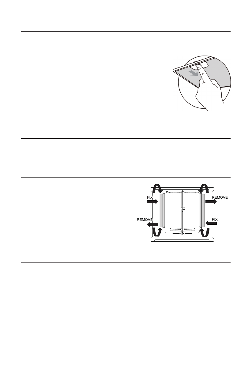
The rangehood and filter should be cleaned regularly.
Switch off or unplug the appliance from the mains supply before carrying out any
maintenance work.
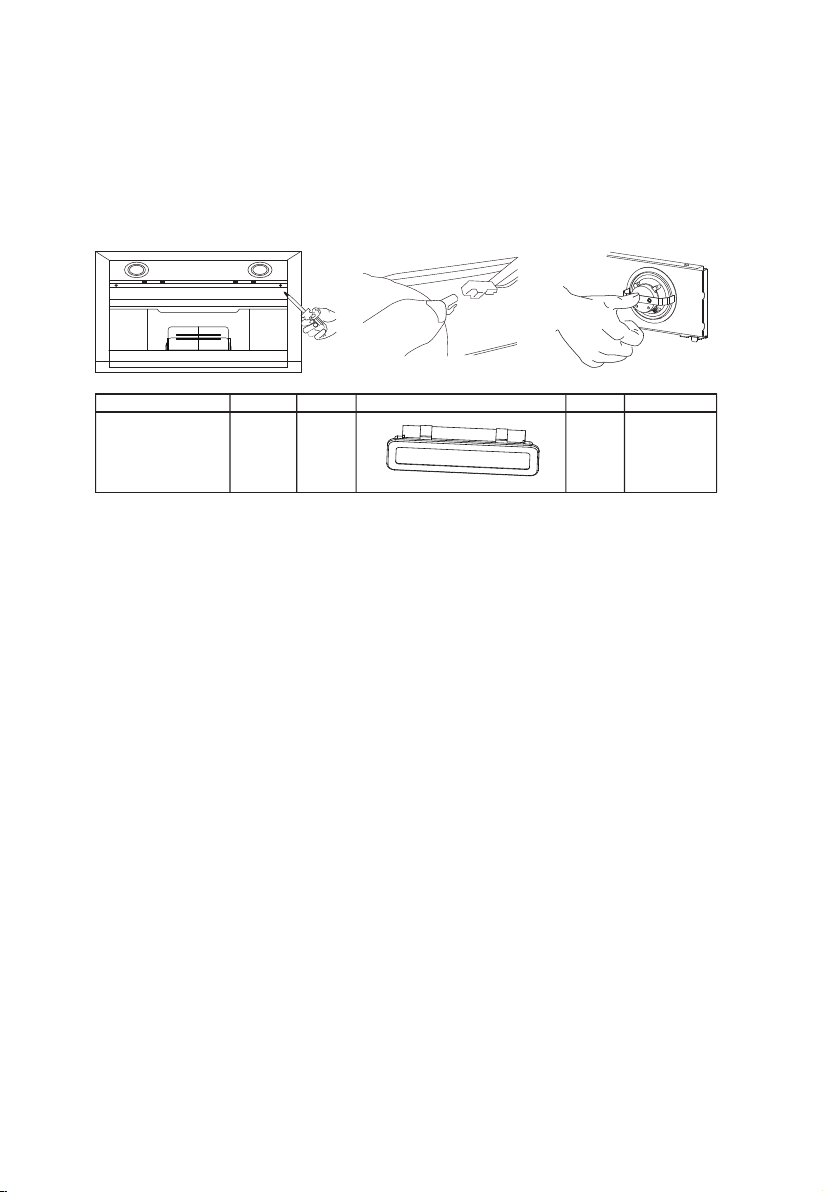
Clean and/or replace the filters after the specified period (fire hazard).
Clean the rangehood using a damp cloth and a neutral liquid detergent.
The appliance will function correctly when using 4 hob elements at most.
3 4
5678
9 10 11
3

1
Ref. Qty.
1
2.1
Rangehood body,complete with: controls,
light, fan motor and filter.
1 Lower decorative flue cover
2.2 1 Upper decorative flue cover
3 1
4
Flange
1 Exhaust Pipe
5 2 The Activated Charcoal filter ( optional )
1
2.1
2.2
3
4
5
1 Instruction Manual
11
12
10
20
21
COMPONENTS
Product Components
Qty. Documentation
10
7
11
Screws 5 x 50
Rangehood fixing bracket
7
Wall Plugs
12
6 Screws 4,2 x 9,5
20 1
21 2 Flue cover fixing bracket
Ref. Qty. Installation Components
2 4
5678
9 10 11
4

300 272
500
Min.
650mm Min.
750mm
240 272
60/100 500
548
585-1028
300
320
322
898
280
282
500
:mm
2 3
5678
9 10 11
5
electric
hotplate
gas
hotplate
NOTE: The exhaust pipe and
decorative flue cover
components for this
rangehood have been
designed to suit a ceiling or
bulkhead height of approx.
2400mm maximum.

INSTALLATION
(3)
255-700
Draw a vertical line up to the ceiling or up to the upper limit, at the centre of the area in which
the rangehood is to be fitted.
Draw a horizontal line A at 970 – 1070 mm above the cooktop.
Draw a horizontal line B at 255 - 700 mm above the horizontal line A.
Draw a horizontal line C at a 288 mm below the horizontal line A .
Mark Points:
Mark a point (1) on the horizontal line A, 80 mm to the left of the vertical reference line.
Repeat this operation on the other side and on the vertical reference line, checking that
the three marks are level.
Mark a point (2) on the horizontal line B, 60 mm to the left of the vertical reference line.
Repeat this operation on the other side, checking that the two marks are on the same
horizontal line.
Mark a point (3) on the horizontal line C, 80 mm to the left of the vertical reference line.
Repeat this operation on the other side , checking that the two marks are level.
Fix the brackets :
Drill holes at the marked points with a ɸ10 mm drill bit.
Insert the Wall Plugs into the holes.
Fix the rangehood fixing bracket 20 with 3 screws (5 x 50) at the horizontal line
A. Fix a flue cover fixing bracket 21 with 2 screws (5 x 50) at the horizontal line C.
WALL DRILLING AND BRACKET FIXING
234
678
9 10 11
First step, proceed with the following:
C
6
Vertical reference line

Hook the rangehood body
Hook the rangehood body to the bracket 20.
Level the rangehood body itself.
Remove the filter from the inside of the rangehood body, fix the screws to wall plugs at
the points (3).
Right Wrong
Upper Decorative Flue Cover
Insert the upper decorative flue cover 2.2 into the lower decorative flue cover 2.1 and drag it
up to the bracket 21.
Fix the upper flue cover onto the bracket 21 with 2 screws 12 (4.2 x 9.5) supplied with the
rangehood.
21
2.1
12
CONNECTIONS
FLUE COVER ASSEMBLY
DUCTED VERSION AIR EXHAUST SYSTEM
When installing the ducted version, connect the rangehood using either
a flexible or rigid pipe ɸ 150 or ɸ 120mm diameter.
If installing a ɸ 120mm air exhaust connection, insert the reducer
flange 3 on the rangehood body outlet.
Fix the pipe 4 in position using sufficient pipe clamps (not supplied).
Remove possible charcoal filters.
Fix a flue cover fixing bracket 21 onto the lower decorative flue cover with 2 screws
12 (4.2x 9.5) supplied with the rangehood.
Lower Decorative Flue Cover
234
57 8
9 10 11
7

USE
234
5 6 8
9 10 11
Speed adjustment. (For some models)
After the rangehood is initially powered on, a beep sound will occur and all touch keys
will illuminate for one second.
Power Key: Pressing the power key will start the rangehood motor on speed 1. Pressing
the power key when the rangehood motor is running will enter the rangehood into a 3
minute delay shutdown cycle, during which, the power key will flash at one second
intervals. Pressing the power key during the 3 minute shutdown cycle, the motor will turn
off immediately.
Plus (+) and Minus (-) Keys: When the rangehood motor is running, you can increase the
speed using the plus key and decrease the speed using the minus key. The digital screen
will display the current motor speed.
Light Key: Pressing the light key turns the light on. Pressing the light key again will turn
the light off.
Light Minus Digital screen Plus Power
8

MAINTENANCE
GREASE FILTERS
ACTIVATED CHARCOAL FILTER (RECIRCULATION VERSION - OPTIONAL)
LIGHTING
LIGHT REPLACEMENT
CLEANING METAL SELF-SUPPORTING GREASE FILTERS
The filters must be cleaned every 2 months of operation, or
more frequently for particularly heavy usage, and can be
washed in a dishwasher.
Remove the filters one by one pushing them towards the back of
the rangehood unit and simultaneously pulling downwards.
Any kind of bending of the filters must be avoided. Before refitting
them again into the rangehood make sure that they are
completely dry. (The colour of the filter surface may change
over time but this has no influence on the filter efficiency).
When fitting the filters into the rangehood please ensure that
they are in the correct position the handle must face outwards.
Remove the metal grease filters.
Remove the saturated activated charcoal filter.
Fit the new filters.
Replace the metal grease filters.
You cannot replaced the light bulbs, the entire light module has to be replaced.
When changing the light modules, the contacts are live.
Before changing the light module(s), unplug the appliance from the mains or switch off
the circuit breaker in the meter box.
Replacing the light modules
The optional charcoal filters are not washable and cannot be regenerated, they must be
replaced approximately every 4 months of operation, or more frequently with heavy usage.
REPLACING THE OPTIONAL ACTIVATED CHARCOAL FILTER
234
5678
10 11
9

Remove the grease filter and carefully remove the 2 screws from the front plate using a
philips head screwdriver.
Disconnect the terminal from the LED light.
Press the LED light on the back of the front plate, and remove it.
Replace the lamp with a compatible 12v DC 1.5 watt LED lamp certified for use in
Australia.
Reverse the above procedures to finalise the lamp replacement process.
Max Power Voltage Picture Lamp Cap ILCOS D code
width/ length
33.2mm x 120mm 1.5W DC 12 V —— DSS-1.5-S-33.2
/120
234
5678
911
10
Dismantle LED light module
Reinstall LED light module

TROUBLESHOOTING BY TECHNICIAN
Fault Cause Solution
Light on, but
motor does not
work
The blades are blocked.
The capacitor is damaged. Replace the capacitor.
The motor is damaged. Replace the motor.
Replace the motor.
The internal wiring of motor is cut off/
disconnected. An unpleasant smell
may be produced.
Both light and
motor do not
work
Apart from the above, check the following:
Light damaged. Replace lights.
Power cord loose. Connect the wires as per the
electric diagram.
Oil leakage
Outlet and the air ventilation entrance
are not tightly sealed. Take down the outlet and seal with glue.
Vibration
The blade, if damaged, can cause
vibrating.
Replace the blade.
The motor is not tightly fastened. Fasten the motor tightly.
The rangehood is not tightly fixed. Fix the rangehood securely.
Insufficient
suction
Adjust the distance.
The distance between the range-
hood and the cook top is too large.
Too much ventilation from open doors
or windows.
The rangehood
Close some doors / windows
isn't level
The fixing screws are not tight
enough or out of level.
Tighten the fixing screw and make the
rangehood level.
Check the blades.
234
5678
9 10
11
WARRANTY & SERVICE
For warranty information, please visit the Cardini website: www.cardini.com.au
For any service issues, please email our customer care team: [email protected]
Table of contents
Other Cardini Ventilation Hood manuals
Popular Ventilation Hood manuals by other brands

KitchenAid
KitchenAid 9763393A Installation instructions and use and care guide

AV Access
AV Access 4KCVH2H user manual

XO Appliance
XO Appliance XOI21SC manual

DeDietrich
DeDietrich DHD1577X Instruction on mounting and use

Windster
Windster UK-611 Installation & operating manual

ETNA
ETNA A4419TZT Instructions for use