Magic 1000 N000925 12/2010 3 / 214
Wichtig: Tor auf Funktion sowie Leichtgängigkeit
prüfen und ggf. einstellen. Die Federspannung des
Tores muss so eingestellt sein, dass es ausbalanciert ist und
sich von Hand leicht, gleichmäßig und ruckfrei öffnen und
schließen lässt.
• Genormte und geeignete Schutzkontaktsteckdose ca. 10 -
50 cm neben Befestigungsposition Antriebskopf.
(Absicherung siehe technische Daten)
• Torantrieb nur in trockene Garagen einbauen.
Montagesatz für Toranschluss am zu montierenden Tortyp
bereithalten bzw. entsprechend dessen Anleitung montieren.
Siehe Hinweise zur Montage ab Seite 162.
Bei Bedarf kann der Antriebskopf um jeweils 90° zur
Laufschiene gedreht werden (Siehe Seite 162 (A)).
Montageschritt D, Seite 163:
1. Spannmutter des Zahnriemens anziehen bis Zahnriemen
nicht mehr in der Führungsschiene aufliegt (entspricht
Maß X).
2. Zahnriemenspannung mittels Spannmutter (Maß B)
entsprechend der Torantriebslänge (Maß A) erhöhen.
Montageschritt G, Seite 165, Einbaumaße:
Nach abgeschlossener Montage
• Tor von Hand langsam öffnen, bis Schlitten hörbar
einrastet.
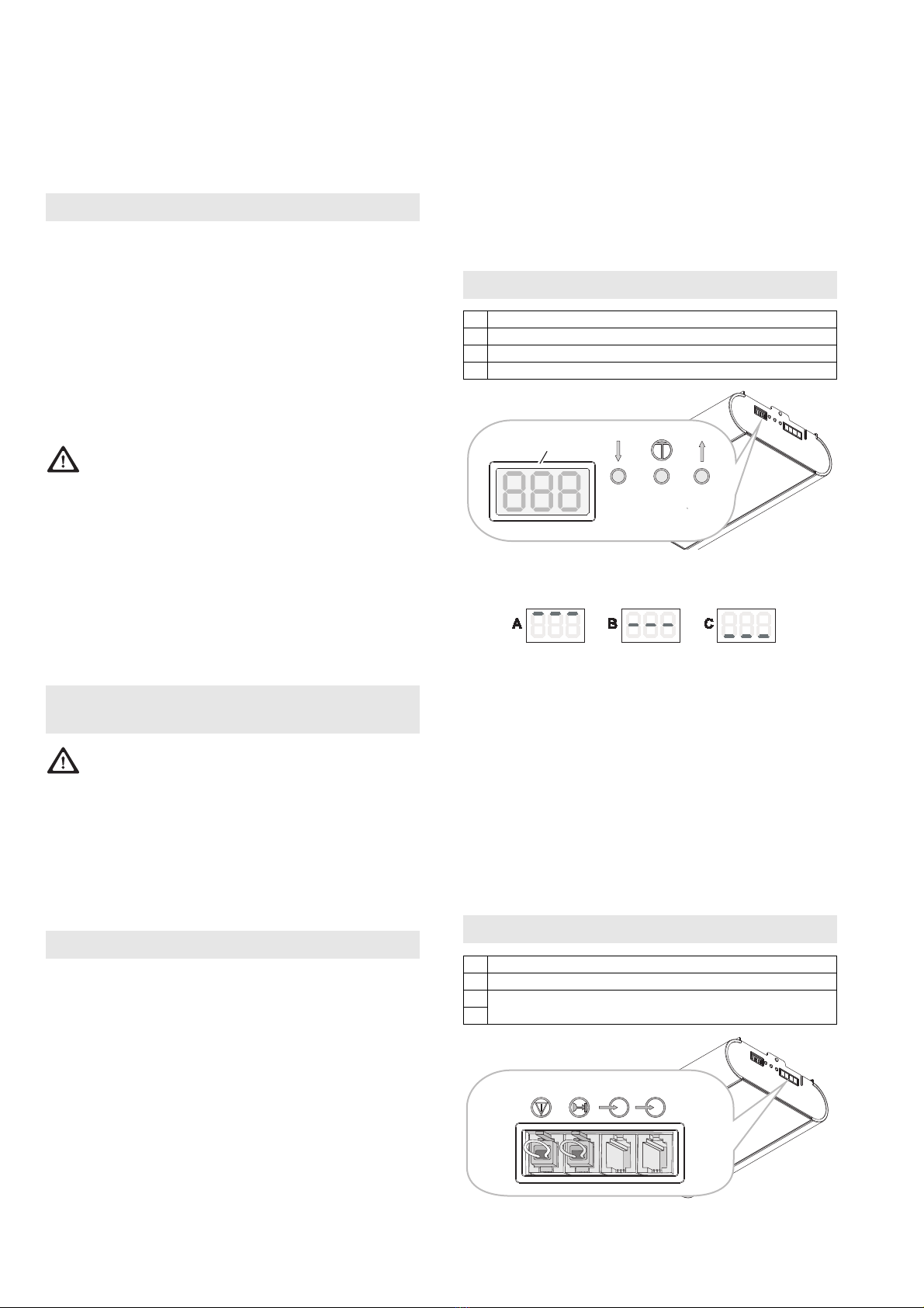
• Netzanschluss herstellen, Display zeigt L4 und die
Torantriebs-Lampe blinkt in 4-er-Intervallen.
• Torantrieb einlernen (Siehe Kapitel 15)
• Handsender einlernen (Siehe Kapitel 16)
• Sicherheitsüberprüfung durchführen (Siehe Kapitel 9)
ACHTUNG: Beim Einlernen des Torantriebs
besteht kein Schutz durch Kraftabschaltung!
Hinweis: Einlernen nur bei Erstmontage oder nach einem
Reset des Torantriebs möglich. Während dem Lernvorgang
keine Tasten drücken.
Vorbereitung: Tor am Torantrieb ankoppeln.
Einlernen mit Handsender
Der Handsender weist zum Zeitpunkt der Auslieferung
und nach einem Reset des Torantriebes folgende
Funktionen auf:
• A Totmann-Betrieb und Feineinstellung "AUF"
• B Totmann-Betrieb und Feineinstellung "ZU"
• C und D Bestätigung (Abspeichern)
Nach dem Einlernen des Torantriebs
wird Taste A zur Fernsteuerung
verwendet, die anderen Tasten können
zur Ansteuerung weiterer, baugleicher
Torantriebe oder Funkempfänger
eingesetzt werden.
Einlernen
• Taste A drücken und gedrückt halten, das Tor bewegt sich
in Öffnungsrichtung.
• Wenn gewünschte Position Endlage „AUF" erreicht ist,
Taste A loslassen. (Korrektur mit Taste B möglich)
• Taste C einmal kurz drücken, Lernvorgang: Der Torantrieb
lernt automatisch „Endlage AUF / ZU“ und Kräfte der
„Wege AUF / ZU“ ein. Torantriebsbeleuchtung blinkt
rhythmisch.
Der Lernvorgang ist abgeschlossen, wenn das Tor offen ist
und die Torantriebsbeleuchtung leuchtet.
Kraftabschaltung gemäß Kapitel 9,
Sicherheitsüberprüfung, überprüfen.
Einlernen ohne Handsender
Am Torantrieb:
• Taster drücken und gedrückt halten, das Tor bewegt
sich in Öffnungsrichtung. Taster loslassen, wenn
gewünschte Öffnungsposition erreicht ist. Eine Korrektur
ist mit Taster möglich.
• Taster Menue betätigen, Der Torantrieb lernt
automatisch „Endlage AUF / ZU“ und Kräfte der „Wege
AUF / ZU“ ein. Torantriebsbeleuchtung blinkt rhythmisch.
Der Lernvorgang ist abgeschlossen, wenn Tor offen ist und
die Torantriebsbeleuchtung leuchtet.
Kraftabschaltung gemäß Kapitel 9,
Sicherheitsüberprüfung überprüfen.
Handsender einlernen:
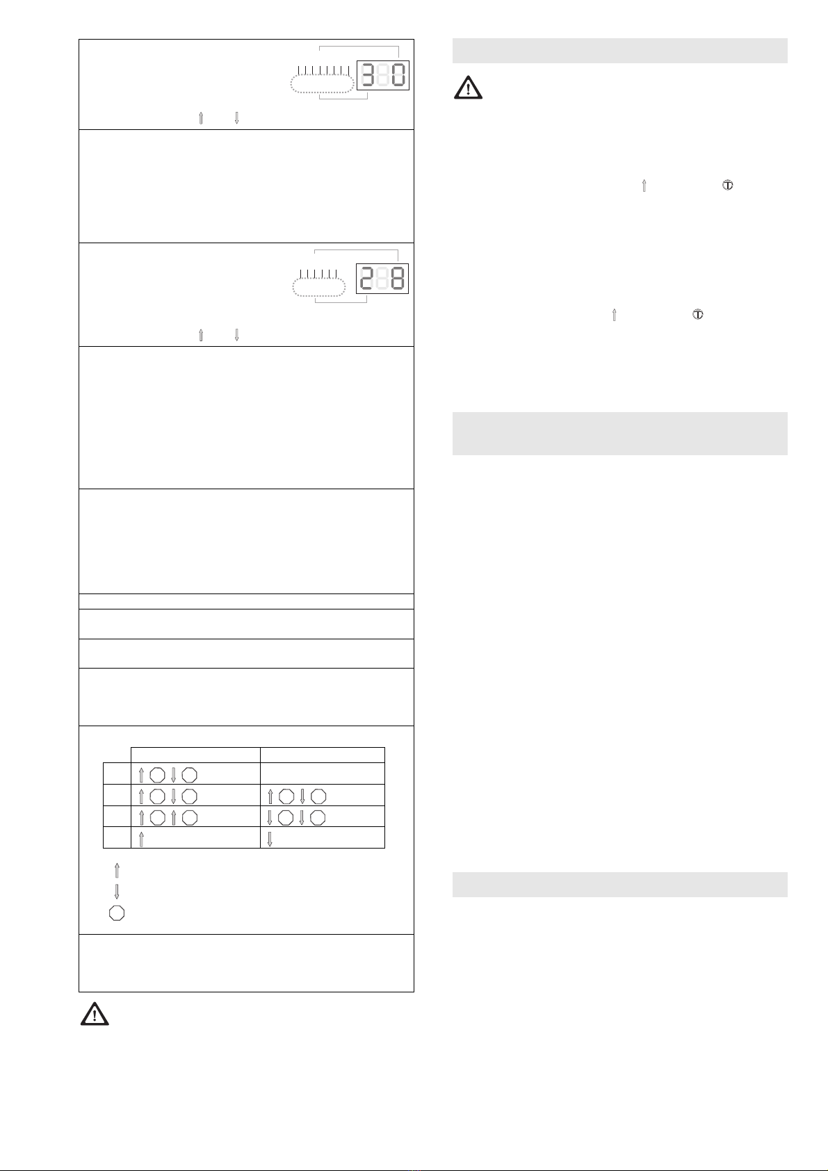
Während einer der 3 Statusmeldungen A, B oder C (Siehe
Kapitel 10) die Taster und gleichzeitig (ca. 1 Sek)
betätigen, im Display blinkt F0.
Gewünschte Funktion mit den Tastern und auswählen.
Die gewünschte Taste am Handsender betätigen, der
Funkbefehl ist eingelernt.
Notiz: Während dem Sendeimpuls wird am Display die
Nummer der Funktion angezeigt.
(Alle) Handsender löschen
Während einer der 3 Statusmeldungen A, B oder C (Siehe
Kapitel 10) die Taster und gleichzeitig >6 Sekunden
betätigen, im Display blinkt FL. Nach 3 Sekunden erscheint
wieder die Statusmeldung.
12 Einbauvorbereitung
13 Montage
Deckensektionaltore
Abb.
Niedersturz Maß G
Euro 30 - 50mm G2
G60 20 - 40mm G3
G60 Max 30 - 50mm G1
Normalsturz
Euro 100 - 120mm G2
G60 100 - 120mm G3
G60 Max 100 - 120mm G1
Schwingtor 20 - 40mm G4
14 Inbetriebnahme
15 Torantrieb einlernen
16 Handsender einlernen / löschen
Funktionen
F0 AUF / Stopp / ZU
F1 AUF / Stopp / AUF
F2 ZU / Stopp / ZU
F3 Stopp
F4 Teilöffnung
F5 Licht AN (Neustart der Lichtzeit)
F6 Licht AN / AUS
F7 AUF
F8 Zu