Ultra 3
ACHTUNG: Beim Einlernen des Torantriebs
besteht kein Schutz durch Kraftabschaltung!
Hinweis: Einlernen nur bei Erstmontage oder nach einem
Reset des Torantriebs möglich. Während dem Lernvorgang
keine Tasten drücken.
Vorbereitung: Tor am Torantrieb ankoppeln.
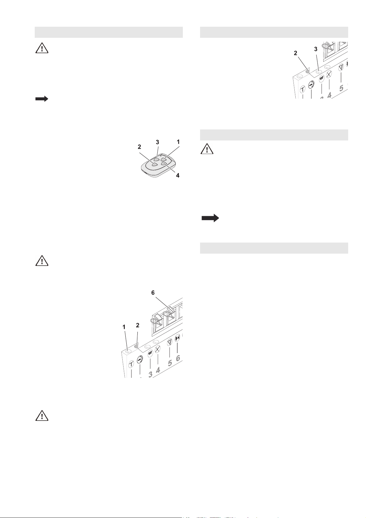
Einlernen mit Handsender
Der Handsender weist zum Zeitpunkt der Auslieferung
und nach einem Reset des Torantriebes folgende
Funktionen auf:
• 1 Totmann-Betrieb und Feineinstellung "AUF"
• 2 Totmann-Betrieb und Feineinstellung "ZU"
• 3 und 4 Bestätigung (Abspeichern)
Nach dem Einlernen des Torantriebs
wird Taste 1 zur Fernsteuerung
verwendet, die anderen Tasten können
zur Ansteuerung weiterer, baugleicher
Torantriebe oder Funkempfänger
eingesetzt werden.
Einlernen
• Taste 1 drücken und gedrückt halten, das Tor bewegt sich
in Öffnungsrichtung.
• Wenn gewünschte Position Endlage „AUF" erreicht ist,
Taste 1 loslassen. (Korrektur mit Taste 2 möglich)
• Taste 3 einmal kurz drücken, Lernvorgang: Der Torantrieb
lernt automatisch „Endlage AUF / ZU“ und Kräfte der
„Wege AUF / ZU“ ein. Torantriebsbeleuchtung blinkt
rhythmisch.
Der Lernvorgang ist abgeschlossen, wenn das Tor offen ist
und die Torantriebsbeleuchtung leuchtet.
Kraftabschaltung gemäß Kapitel
Sicherheitsüberprüfung überprüfen.
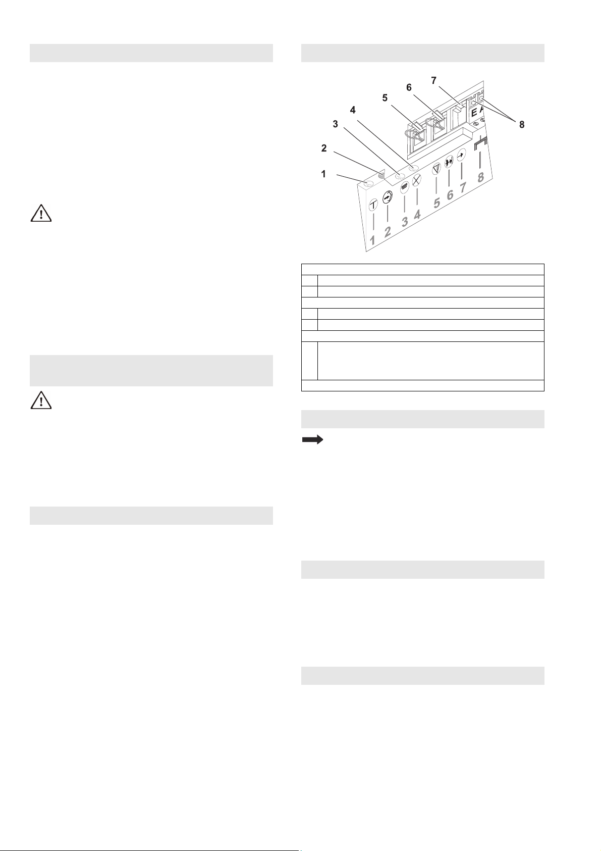
Einlernen ohne Handsender
Am Torantrieb:
• Westernstecker (6) abziehen
• Taster „Impuls“ (1) drücken
und gedrückt halten, das Tor
bewegt sich in
Öffnungsrichtung.
• Wenn gewünschte Position
Endlage „AUF“ erreicht ist,
Taster „Impuls“ (1) loslassen.
• Westernstecker (6) wieder
einstecken. (Korrektur mit
Taster „Impuls“ möglich)
• Taster „Programm“ (2)
drücken, Lernvorgang: Der
Torantrieb lernt automatisch
„Endlage AUF / ZU“ und Kräfte der „Wege AUF / ZU“ ein.
Torantriebsbeleuchtung blinkt rhythmisch.
Der Lernvorgang ist abgeschlossen, wenn Tor offen ist und
die Torantriebsbeleuchtung leuchtet.
Kraftabschaltung gemäß Kapitel
Sicherheitsüberprüfung überprüfen.
Handsender einlernen:
• Taster „Programm" (2) drücken,
LED (3) blinkt 1-mal
• Innerhalb 20 Sec. eine noch
nicht eingelernte Taste am
Handsender drücken, LED (3)
leuchtet, das Einlernen ist
abgeschlossen.
(Alle) Handsender löschen
Taster „Programm" (2) >5 Sec. drücken, LED (3) blinkt
zunächst langsam, anschließend schnell und erlischt. Alle
eingelernten Handsender sind gelöscht.
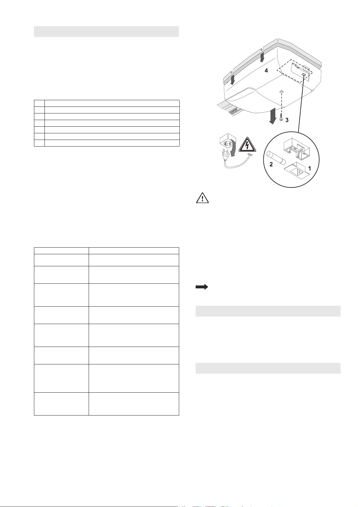
VORSICHT: Sorgloser Umgang mit dem Torantrieb
kann zu Verletzungen oder Sachbeschädigungen
führen. Grundlegende Sicherheitsregeln beachten:
Beim Öffnen und Schließen des Tores die Schwenkbereiche
innen und außen freihalten. Kinder fernhalten.
Die Torbewegungen können über den mitgelieferten
Handsender oder optional anschließbare Schaltelemete (z.B.
Wandtaster) ausgelöst bzw. gestoppt werden.
Externe Zusatzeinrichtungen (z.B. Not-Stopp) können
angeschlossen werden.
Der Antrieb darf nicht ohne angekoppeltes Tor
betrieben werden. Die Elektronik würde
dadurch falsche Kraftwerte einlernen.
Funktionsstörungen können die Folge sein.
Vorwarnzeit
Bei aktivierter Vorwarnzeit leuchtet bei jeder Ansteuerung
des Torantriebes zunächst nur die Torantriebsleuchte.
3 Sekunden später wird der Motorlauf gestartet (werkseitige
Einstellung 0 Sekunden).
Vorwarnzeit einstellen:
• Taster „Programm“ (2) 1x betätigen, rote LED (3) blinkt 1x.
• Taster „Impuls“ (1) 2x betätigen, rote LED (3) blinkt 3x.
• Taster „Programm“ 1x betätigen, Funktion Vorwarnzeit ist
eingelernt.
Zum Wiederausschalten der Funktion Vorwarnzeit gleiche
Vorgehensweise wiederholen.
Torantrieb einlernen Handsender einlernen / löschen
Bedienung
Einstellungen / Zusatzfunktionen