1000DF00444 Iss. 2 5/210
Operating Precautions
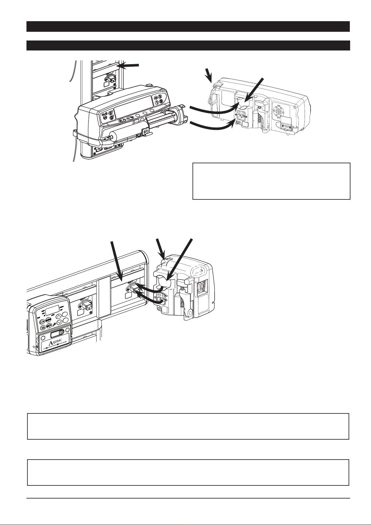
Mounting the Pump
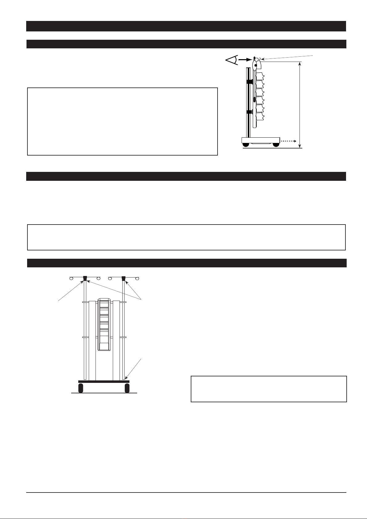
H•The pumps fitted to the Docking Station must be mounted within 1.0m above or below the patient’s heart.
The most accurate pressure monitoring in the extension set is achieved when the pump is positioned close
to the patients heart level.
I•Do not mount the Docking Station with the syringe pointing upwards as this could lead to an infusion of
air which may be in the syringe.To protect against the introduction of air the user should regularly monitor
the progress of the infusion, syringe, extension line and patient connections and follow the priming
procedure specified in the relevant Directions For Use.
•Do not mount the Docking Station with the mains inlet pointing upwards as this could affect the electrical
safety in the event of a fluid spill over the Docking Station. Ensure that the Docking Station is mounted in
the vertical position.
•The fixing bar that the Docking Station is fixed to must be rated at a minimum of four times the
weight of the fully loaded Docking Station (see the table in 'Specifications' section for weights of each
Docking Station configuration).
•The Alaris® DS Docking Station trolley has been designed to carry a maximum total of 9 pumps (6 syringe
pumps and 3 volumetric pumps). Do not use a configuration larger than this on the trolley (see the table
in 'Specifications' section).
•The Docking Station should not be fitted to a mobile pole unless the stability and strength of the assembly
has been evaluated to IEC/EN60601-1 for mobile equipment.
•No equipment other than Alaris® Infusion Pumps should be connected to the mains outlets.The permitted
system earth leakage current may be exceeded if other equipment is connected.
Electromagnetic Compatibility & Interference
M•This Docking Station (with pumps fitted) is protected against the effects of external interference, including
high energy radio frequency emissions, magnetic fields and electrostatic discharge (for example, as
generated by electrosurgical and cauterising equipment, large motors, portable radios, cellular telephones
etc.) and is designed to remain safe when unreasonable levels of interference are encountered.
•The Docking Station falls outside the scope of CISPR 11, as it utilises no alternating currents or switched
signals above 9KHz.Therefore, its RF emissions are very low and are not likely to cause any interference with
the nearby electronic equipment. However, this Docking Station (with pumps fitted) emits a certain level
of electromagnetic radiation which is within the levels specified by IEC/EN60601-1-2 and IEC/EN60601-2-
24. If the Docking Station (with pumps fitted) interacts with other equipment, measures should be taken
to minimise the effects, for instance by repositioning or relocation.
Hazards
B•An explosion hazard exists if the Docking Station is used in the presence of flammable anaesthetics.
Exercise care to locate the Docking Station away from any such hazardous sources.
A•Dangerous Voltage: An electrical shock hazard exists if the Docking Station's casing is opened or removed.
Refer all servicing to qualified service personnel.
•When connected to an external power source, a three-wire (Live, Neutral, Earth) supply must be used. If the
integrity of the external protective conductor in the installation or its arrangement is in doubt, the Docking
Station should not be used.
•If this Docking Station is dropped, subjected to excessive moisture, fluid spillage, humidity or high
temperature, or otherwise suspected to have been damaged, remove it from service for inspection by
a qualified service engineer. When transporting or storing the Docking Station, use original packaging
where possible, and adhere to temperature, humidity and pressure ranges stated in the 'Specifications
'section and on the outer packaging.