cod. +050000520 - rel. 1.6 - 27.11.2017
SFFS000000: Rivelatore di fumo / Smoke detector
SFFS000000: Rivelatore di fumo / Smoke detector
Descrizione
Il rivelatore di fumo ottico reagisce alla presenza di prodotti causati dalla combustione, (fumi visibili). Il prin-
cipio di funzionamento si basa sulla tecnica di dispersione della luce, (eetto Tyndall). Il rivelatore è integrato
ed è parte attiva dei sistemi di allarme, nei quali si vuole implementare una linea di rivelazione antiincendio. Il
dispositivo si integra con i controlli Carel, ed è costruito in conformità alla normativa EN 54-7.
Caratteristiche tecniche
Materiale plastico ABS
Colore Bianco
Alimentazione 12...28 Vdc
Assorbimento medio 50µA a 24 Vdc
Assorbimento in allarme 25mA a 24 Vdc
Visibilità led 360° (doppio led)
Temperatura di stoccaggio -10…+70°C
Temperatura di funzionamento -10…+70°C
Velocità max. aria 0,2 m/s
Umidità relativa <93% non condensante
Grado di protezione IP 20
Attivazione test magnetico Si
Relè max. 1A 30Vdc
Ripetitore di segnale 14mA a 24 Vdc
copertura del sensore: 40m2max
Collegamento cavo schermato sez. min 0,5 mm2
Codici Tensione di alimentazione
SFFS000000 12…24 Vdc
Tab. 1
Manutenzione
Per il corretto funzionamento del rivelatore, occorre eettuare la sua manutenzione periodica secondo le
norme nazionali.
Test periodico
Vericare il corretto funzionamento del rivelatore mediante un generatore di fumo (attenzione a non dan-
neggiare o sporcare il sensore). Una simulazione di allarme può essere eettuata mediante l’attivazione del
reed interno con una calamita stimolando la base nel punto indicato “Reed” sullo schema di collegamento.
Attenzione che il test con reed non verica il corretto funzionamento della rivelazione del fumo.
Pulizia
Pulire il rilevatore periodicamente con un getto di aria compressa soato all’interno della camera di rive-
lazione. Smontare il rivelatore svitando le due apposite viti e aprire la camera di rivelazione. Terminata la
pulita ri-assemblare facendo attenzione al montaggio del disco di fondo (far combaciare il reed interno con
il numero 4 stampigliato sul fondo). Chiudere il rivelatore con le due viti senza stringere eccessivamente.
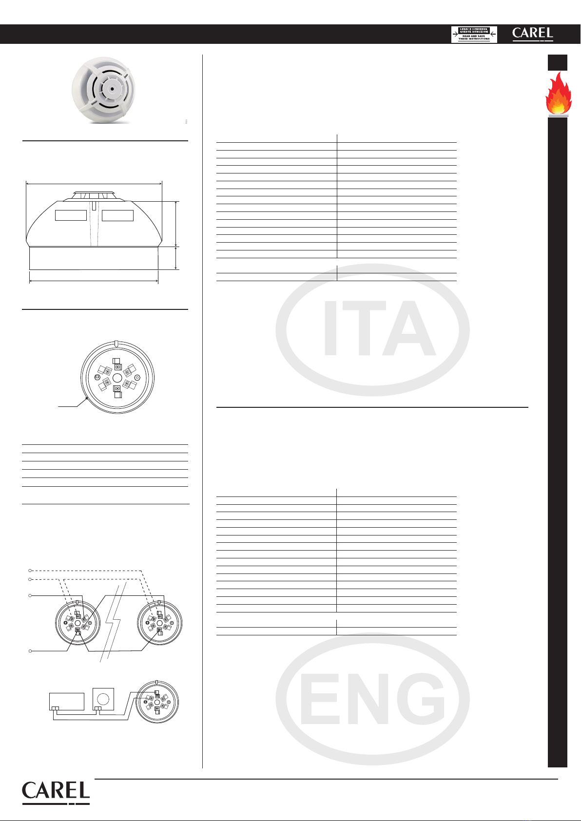
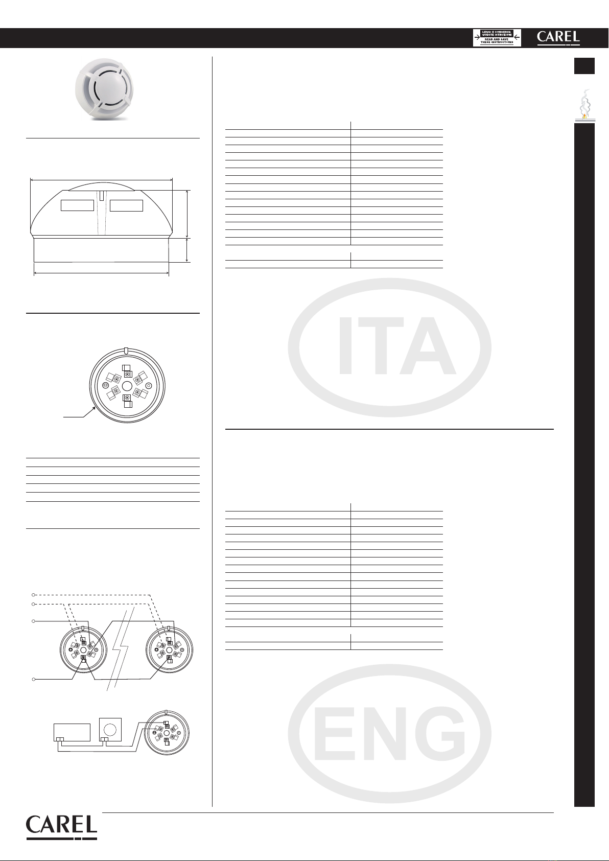
1/+ Ingresso linea positivo / Positive line input
2/R Relè / Relay
3/R Relè / Relay
4/SCR Uscita negativa rip. / Repeater neg. output
5/- Negativo linea / Negative line
6/+ Uscita linea positivo / Positive line output
Fig. 1
Dimensioni / Dimensions
Collegamento elettrico / Electrical connection
Fig. 2
Fig. 3
cod. +050000520 - rel. 1.6 - 27.11.2017
CAREL INDUSTRIES HQs
Via dell’Industria, 11 - 35020 Brugine - Padova (Italy)
Tel. (+39) 049 9716611 – Fax (+39) 049 9716600
Description
The optical smoke detector senses the presence of combustion byproducts (visible smoke). The operating
principle is based on the light scattering technique (Tyndall eect). The detector is used as an active compo-
nent in alarm systems requiring a re detection line. The device can be integrated into Carel controllers, and
is made in compliance with EN 54-7.
Technical specications
Plastic ABS
Colour White
Power supply 12...28 Vdc
Normal current 50µA a 24 Vdc
Alarm current 25mA a 24 Vdc
LED visibility 360° (double led)
Storage temperature -10…+70°C
Operating temperature -10…+70°C
Max. speed air 0,2 m/s
Relative humidity <93% not-condensing
Index of protection IP 20
Testing by magnet Yes
Relay max. 1A 30Vdc
Signal repeater 14mA a 24 Vdc
Sensor coverage: 40m2max
Shielded connection cable sez. min 0,5 mm2
Code Power supply
SFFS000000 12 to 24 Vdc
Tab. 1
Maintenance
For correct detector operation, periodical maintenance must be performed depending on the country disposal.
Periodical testing
Check correct detector operation using a smoke generator (making sure not to damage or dirty the sensor).
An alarm can also be simulated by activating the internal reed switch by magnet at the point marked “Reed”
on the wiring diagram. Note however that the reed test does not verify correct smoke detection.
Cleaning
Clean the detector periodically by blowing compressed air into the detection chamber. Remove the detector
by unscrewing the two screws and open the detection chamber. After cleaning reassemble the unit, paying
special attention to the position of the base (make sure the internal reed switch is aligned with number 4
stamped on the base). Close the detector using the two screws, without over-tightening.
Schemi elettrici di collegamento /
Wiring diagrams
1
2
3
4
5
6
1
2
3
4
5
6
TAMPER
+LINEA
-LINEA
Allacciamento alla LINEA / Connection LINE
Ripetitore / Repeater
1
2
3
4
5
6+-
1
2
3
4
5
6
+-
POWER
SUPPLY
+
-
Collegamento al Relè / Connection to Relay
1
2
3
4
5
6
1
2
3
4
5
6
TAMPER
+LINEA
-LINEA
Allacciamento alla LINEA / Connection LINE
Ripetitore / Repeater
1
2
3
4
5
6+-
1
2
3
4
5
6
+-
POWER
SUPPLY
+
-
Collegamento al Relè / Connection to Relay
100
20 39
106
1
2
3
4
5
6
Reed