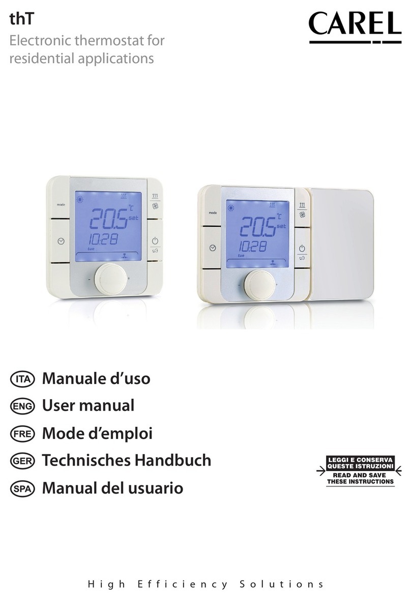
Carel thT THB000AAF0 User manual

Integrated Control Solutions For Energy Savings
thT
Electronic thermostat for
residential applications
Manuale d’uso
User manual


3“manuale”+03022**** - rel. 0.1 - 00.00.2014 - preliminary version
AVVERTENZE
Gli umidificatori CAREL S.p.A. sono prodotti avanzati, il cui funzionamento è
specificato nella documentazione tecnica fornita col prodotto o scaricabile,
anche anteriormente all’acquisto, dal sito internet www.carel.com. Ogni
prodotto CAREL S.p.A., in relazione al suo avanzato livello tecnologico,
necessita di una fase di qualifica/configurazione/programmazione affinché
possa funzionare al meglio per l’applicazione specifica. La mancanza di tale
fase di studio, come indicata nel manuale, può generare malfunzionamenti
nei prodotti finali di cui CAREL S.p.A. non potrà essere ritenuta responsabile.
Il cliente (costruttore, progettista o installatore dell’equipaggiamento finale)
si assume ogni responsabilità e rischio in relazione alla configurazione del
prodotto per il raggiungimento dei risultati previsti in relazione all’installazione
e/o equipaggiamento finale specifico. CAREL S.p.A. in questo caso, previ
accordi specifici, può intervenire come consulente per la buona riuscita della
installazione/start-up macchina/utilizzo, ma in nessun caso può essere ritenuta
responsabile per il buon funzionamento dell’umidificatore ed impianto finale
qualora non siano state seguite le avvertenze o raccomandazioni descritte
in questo manuale o in altra documentazione tecnica del prodotto. In
particolare, senza esclusione dell’obbligo di osservare le anzidette avvertenze
o raccomandazioni, per un uso corretto del prodotto si raccomanda di
prestare attenzione alle seguenti avvertenze:
• PERICOLO SCOSSE ELETTRICHE
• L’umidificatore contiene componenti sotto tensione elettrica. Togliere
l’alimentazione di rete prima di accedere a parti interne o in caso di
manutenzione e durante l’installazione;
• PERICOLO PERDITE D’ACQUA
• l’umidificatore carica/scarica automaticamente e costantemente quantità
d’acqua. Malfunzionamenti nei collegamenti o nell’umidificatore possono
causare perdite;
• Negli umidificatori isotermici: PERICOLO DI USTIONE
• L’umidificatore contiene componenti ad alta temperatura (100°C/212°F);
• Negli umidificatori isotermici a gas: PERICOLO FUGHE DI GAS
• L’umidificatore è allacciato alla rete del gas. Malfunzionamenti nei
collegamenti o nell’umidificatore possono causare perdite.
• L’installazione del prodotto deve obbligatoriamente comprendere una
connessione di terra, utilizzando l’apposito morsetto di colore giallo-verde
presente nell’umidificatore.
• Condizioni ambientali e tensione di alimentazione devono essere conformi
ai valori specificati nelle etichette‘dati di targa’ del prodotto.
• Il prodotto è progettato esclusivamente per umidificare ambienti in
modo diretto o mediante sistemi di distribuzione (condotte). Inoltre per
gli umidificatori-adiabatici-atomizzatori-ad-acqua-in-pressione è prevista
anche l’umidificazione attraverso il telaio di atomizzazione.
• Installazione, utilizzo e manutenzione devono essere eseguite da personale
qualificato, consapevole delle precauzioni necessarie e in grado di
effettuare correttamente le operazioni richieste.
• Per la produzione di vapore si deve utilizzare esclusivamente acqua con
caratteristiche indicate nel presente manuale.
• Attenzione, in caso di umidificatori-adiabatici-atomizzatori-ad-acqua-in-
pressione è obbligatorio utilizzare acqua potabile demineralizzata (come
specificato nel manuale). Inoltre, è necessario raccogliere le particelle
d’acqua non assorbite dall’aria, attraverso la vasca raccogligoccia (nella
parte di umidificazione) e il separatore di gocce (nella parte di fine
umidificazione).
• Tutte le operazioni sul prodotto devo essere eseguite secondo le istruzioni
contenute nel presente manuale e nelle etichette applicate al prodotto. Usi
e modifiche non autorizzati dal produttore sono da considerarsi impropri.
CAREL S.p.A. non si assume alcuna responsabilità per tali utilizzi non
autorizzati.
• Non tentare di aprire l’umidificatore in modi diversi da quelli indicati nel
manuale.
• Attenersi alle normative vigenti nel luogo in cui si installa l’umidificatore.
• Tenere l’umidificatore fuori dalla portata di bambini e animali.
• Non installare e utilizzare il prodotto nelle vicinanze di oggetti che possono
danneggiarsi a contatto con l’acqua (o condensa d’acqua). CAREL S.p.A.
declina ogni responsabilità per danni conseguiti o diretti a seguito di
perdite d’acqua dell’umidificatore.
• Non utilizzare prodotti chimici corrosivi, solventi o detergenti aggressivi
per pulire le parti Interne ed esterne dell’umidificatore, salvo non vi siano
indicazioni specifiche nei manuali d’uso.
• Non fare cadere, battere o scuotere l’umidificatore, poiché le parti interne e
di rivestimento potrebbero subire danni irreparabili.
• Per prodotti umidificatori-adiabatici-atomizzatori-ad-acqua-in-pressione:
la distribuzione dell’acqua atomizzata deve essere condotta attraverso
apposito‘rack’di atomizzazione o attraverso sistemi di distribuzione previsti
da CAREL S.p.A.
• Per i prodotti isotermici: sono progettati per produrre vapore a pressione
atmosferica, e non vapore in pressione. CAREL S.p.A. sconsiglia e declina
ogni responsabilità per l’uso di dispositivi di distribuzione diversi da quelli
previsti.
CAREL S.p.A. adotta una politica di continuo sviluppo. Pertanto si riserva il
diritto di effettuare modifiche e miglioramenti a qualsiasi prodotto descritto
nel presente documento senza preavviso. I dati tecnici presenti nel manuale
possono subire modifiche senza obbligo di preavviso.
La responsabilità di CAREL S.p.A. in relazione al proprio prodotto è regolata
dalle condizioni generali di contratto CAREL S.p.A. pubblicate nel sito www.
carel.com e/o da specifici accordi con i clienti; in particolare, nella misura
consentita dalla normativa applicabile, in nessun caso CAREL S.p.A., i suoi
dipendenti o le sue filiali/ affiliate saranno responsabili di eventuali mancati
guadagni o vendite, perdite di dati e di informazioni, costi di merci o servizi
sostitutivi, danni a cose o persone, interruzioni di attività, o eventuali danni
diretti, indiretti, incidentali, patrimoniali, di copertura, punitivi, speciali o
consequenziali in qualunque modo causati, siano essi contrattuali, extra
contrattuali o dovuti a negligenza o altra responsabilità derivanti dall’ utilizzo
del prodotto o dalla sua installazione, anche se CAREL S.p.A. o le sue filiali/
affiliate siano state avvisate della possibilità di danni.
SMALTIMENTO
L’umidificatore è composto da parti di metallo e parti di plastica. In riferimento
alla Direttiva 2002/96/CE del Parlamento Europeo e del Consiglio del 27
gennaio 2003 e alle relative normative nazionali di attuazione, Vi informiamo
che:
1. sussiste l’obbligo di non smaltire i RAEE come rifiuti urbani e di effettuare,
per detti rifiuti, una raccolta separata;
2. per lo smaltimento vanno utilizzati i sistemi di raccolta pubblici o privati
previsti dalla leggi locali. È inoltre possibile riconsegnare al distributore
l’apparecchiatura a fine vita in caso di acquisto di una nuova;
3. questa apparecchiatura può contenere sostanze pericolose: un uso
improprio o uno smaltimento non corretto potrebbe avere effetti negativi
sulla salute umana e sull’ambiente;
4. ilsimbolo (contenitoredi spazzaturasuruote barrato)riportato sulprodotto
o sulla confezione e sul foglio istruzioni indica che l’apparecchiatura è stata
immessa sul mercato dopo il 13 Agosto 2005 e che deve essere oggetto
di raccolta separata;
5. in caso di smaltimento abusivo dei rifiuti elettrici ed elettronici sono
previste sanzioni stabilite dalle vigenti normative locali in materia di
smaltimento.
Garanzia sui materiali: 2 anni (dalla data di produzione, escluse le parti di
consumo).
Omologazioni: la qualità e la sicurezza dei prodotti CAREL S.P.A. sono
garantite dal sistema di progettazione e produzione certificato ISO 9001,
nonché dai marchi (inserire marchi specifici del prodotto).
ENG

5“manuale”+03022**** - rel. 0.1 - 00.00.2014 - preliminary version
ENG
Content
1. GENERAL FEATURES 7
1.1 Models ......................................................................................................................7
1.2 Dimensioni.............................................................................................................7
1.3 Technical specifications...............................................................................13


7“manuale”+03022**** - rel. 0.1 - 00.00.2014 - preliminary version
ENG
1. GENERAL FEATURES
ThT Thermostat is the CAREL room thermostat that allows users to
control the temperature in residential or light commercial environments,
providing of simplified interface that is ideal for end users. Temperature
set is simple and intuitive, using the knob on the front panel. thT also
allows the user to make some settings, such as the operating mode and
time bands. Compact dimensions and elegant design make it suitable for
all types of rooms, as well as being ideal both as a simplified HMI (Human
Unit Interface) for heat pumps, rooftop units, AHUs, etc. and as zone
controller display for centralised systems.
The RS485 serial connection over Modbus® protocol means architecture
can be implemented in which multiple displays are connected to a
controller to create synergic control logic with programmable controllers.
It can works in stand–alone mode as ambient thermostat or connected
to programmable controllers as zone control in the radiator systems too.
Depending on the model, thT thermostat is fitted for Flush or Wall
mounting and power supply is 230 Vac.
A temperature sensor is available in all models in order to manage
the comfort in the residential ambient, and a Humidity sensor only on
specific models.
thT is compatible with the main flush mount distribution boxes available
on the market.
1.1 Models
Codes FLUSH MOUNTING:
THB000AAF0 tht thermostat temperature - flush mounting - neutral
version
THB000ACF0 tht thermostat temperature and humidity - flush
mounting - neutral version
Codes WALL MOUNTING:
THB000AAW0 tht thermostat temperature - wall mounting - neutral
version
THB000ACW0 tht thermostat temperature and humidity - wall
mounting - neutral version
1.2 Dimensioni
Dimension flush mounting
86
86
8 22,55 28
48
Dimensions of rear part (mm)
74
60
74
60
Dimension wall mounting
86
8 28
143
Dimensions of rear part (mm)
E
131
83,5
86
Installation warnings
• These thT thermostats have been designed for wall or flush mount
assembly, on distribution boxes compliant with the standards in force;
• before performing any operations on the thermostat, disconnect the
power supply from the device by switching the main switch on the
electrical panel OFF. Then remove the front part of the thermostat from
the rear to make the electrical connections;

8
“manuale”+03022**** - rel. 0.1 - 00.00.2014 - preliminary version
ENG
• for the serial connection use three-wire shielded cable, AWG 20-22. The
length of the network must not exceed 500 m. For extended networks
fit a 120 Ohm resistor between RX/TX+ and RX/TX- on the first and last
device, to avoid possible communication problems.
Assembly for the flush mounting
To fit the rear part of the terminal use a flush mount box with a min.
diameter of 65 mm and a minimum depth of 31 mm.
1. Detach the front from the rear of the thT thermostat using a
screwdriver;
2. Make the electrical connections according with the schematic;
3. Fasten the rear to the flush mount box using the 2 screws supplied:
4. Finally reposition the thT thermostat the original position and ensure
to fix it with clicks into place.
Dismantling
Wiring
GND
Rx+/Tx+
Rx–/Tx–
GND
A
B
N 230V~
L 50/60Hz
NO
NC
Com Relay
Power
supply
Serial connections
Exploded
click
4
5
6
click
4
5
6
Assembly for the wall mounting
1. Separate the front from the rear of the terminal using a screwdriver;
2. To remove cover A1, unscrew screw A2 and press the point of
attachment; access terminal block A3;
3. Drill the holes in the wall (dia. 5 mm); then insert the plugs and screws
supplied, making sure that the electrical wires pass through hole E;
4. Make the electrical connections according with the schematic;
5. Close cover A1, completing the same operations as described above
in reverse;
6. Finally reposition the thT thermostat the original position and ensure
to fix it with clicks into place.
Dismantling
b
Cover dismantling
A1
A2
A3
A3
E
POWER
SUPPLY
Serial connection
RelayA B
Rx+Tx+
Rx-Tx-
GND
NC
Com
NO
N 250 V~
L 50/60 Hz
Is It Possible to change the rotation of the display moving the base in the
other three possible positions:
1. remove the screw;
2. remove the base;
3. turn the base and place it in the right position;
4. tighten the screw;

9“manuale”+03022**** - rel. 0.1 - 00.00.2014 - preliminary version
ENG
Dismantling
Insert a screwdriver into the clot at the top and press downwards to
detach the display.
General notes
Avoid installing the terminal in environments with the following
characteristics:
• relative humidity greater than the value specified;
• strong vibrations or knocks;
• exposure to water sprays;
• exposure to aggressive and polluting atmospheres (e.g.: sulphur and
ammonia fumes, saline mist, smoke) so as to avoid corrosion and/or
oxidation;
• strong magnetic and/or radio frequency interference (for example,
near transmitting antenna);
• exposure to direct sunlight or the elements in general;
• large and rapid fluctuations in the room temperature;
• environments where explosives or mixes of flammable gases are
present;
• exposure to dust (formation of corrosive patina with possible oxidation
and reduction of insulation).
Electrical connections
L
N
N
thT
thT - ID51
L
AC85~ 250 V 50/60 Hz
Power line
NO
COM Digital
output
NC
GND
B(-)
A(+)
Serial
connection
L
N
N L
AC85~ 250 V 50/60 Hz
Power line
NO
COM
NC
GND
B(-)
A(+)
Load
thT - ID52
L
N Power line
NO
COM
NC
GND
B(-)
A(+)
Load
thT - ID82
L
N Power line
NO
COM
NC
GND
B(-)
A(+)
A (Rx+/Tx+)
B (Rx-/Tx-)
GND
Load
120Ω120Ω
Serial connection
RS485 Modbus
A+ B- Gnd NC Com NO N L
Example of network connections
L
N
N
thT
thT - ID51
L
AC85~ 250 V 50/60 Hz
Power line
NO
COM Digital
output
NC
GND
B(-)
A(+)
Serial
connection
L
N
N L
AC85~ 250 V 50/60 Hz
Power line
NO
COM
NC
GND
B(-)
A(+)
Load
thT - ID52
L
N Power line
NO
COM
NC
GND
B(-)
A(+)
Load
thT - ID82
L
N Power line
NO
COM
NC
GND
B(-)
A(+)
A (Rx+/Tx+)
B (Rx-/Tx-)
GND
Load
120Ω120Ω
Serial connection
RS485 Modbus

10
“manuale”+03022**** - rel. 0.1 - 00.00.2014 - preliminary version
ENG
Display
1
7
10
13
11
12
8
9
14
15
2
3
4
5
6
Key:
1. Operating mode
2. Main field
3. Time Band active
4. Secondary field
5. Day of week
6. Alarm
7. Fan/Heating function
8. Fan speed/Forced heating time
9. Temperature unit
10. Key locked
11. Set point
12. Humidity
13. Current time band
14. Valve on
15. Forced heating
Key Function
Key Description Function
Select mode Press shortly, you can select different
mode you need.
Check
humidity
Press for 3 seconds, you can check
the current humidity with the display
“XX%rH”, if there is no humidity sensor,
the display will show“no H”
Fan If it is Fan key, you can select different fan
speed by pressing it.
Heating If it is Heating key, you can select force
heating time by pressing it.
Clock Press shortly, you can enable time band,
Eco or Party, and cancel them.
Press for 3 seconds, you can select clock
setting, time band setting, Eco set point
or Party set point.
On/Off key Press shortly, you can turn on/off the
thermostat.
Lock key Press 3 seconds, you can lock/unlock all
the keys.
Knob By rotating the knob, you can adjust the
parameter or set point.
Key Description Function
+ Parameter
setting
If you want to set parameter, you can
operate as following
a. turn off the thermostat
b. press and hold“ + “ for 5
seconds
c. rotate the knob, set the password to 22
d. select parameter and change its value
by rotating and press the knob.
Exit form menu:
• Waiting 20s without any operation;
• Confirm with any of the 4 key pressed;
Humidity Check
Turn on the thermostat (model with humidity version), press and hold
“mode” for 3 seconds, the LCD will display “%rH value”, if thT is only
temperature sensor (no humidity), the display will show“no H”.
Key Fan/Heating
The key “ “ is configured as Fan ( ) or Heating ( ) mode
according with parameter FH (Fan – Heating).
• FH = 00 -> Fan
• FH = 01 -> Heating
This information is sent by modbus (Coil 53).
When“FH”= 0
Pressing the button , we can select the desired speed (min, med,
max) or automatic (Auto) and send this information through Modbus
RTU (Register 7)
Min speed fan
Medium speed fan
Maximum speed fan
Auto speed fan
When“FH”= 1
The button is configured for managing heating device, pressing it we can
select the time where the unit will be forced 100% (20, 40 or 60 min). This
information is sent by Modbus RTU (Register 8)
Pressing the button, we can set the desired time of heating forced. Every
press of the button, increment the time to: 20, 40, 60 min, and on the
display will be shown.
+ = 20 min
+ = 40 min
+ = 60 min
When relay is active the icon is shown.
• If “FS” parameter is = 0 (thermostat control), the fan / heating button
status is decided by thermostat.
• If “FS” parameter is = 1 (supervisor control) and “FH” = 0, the button is
configured as “fan speed button” and status is decided by supervisor
(Registers 70).
• If “FS” parameter is = 1 (supervisor control) and “FH” = 1, the button
is configured as “heating button” and status is decided by supervisor
(Registers 71).

11 “manuale”+03022**** - rel. 0.1 - 00.00.2014 - preliminary version
ENG
Clock Setting
Turn on the thermostat, press and hold“ “ for 5 seconds, the secondary
field display“hh:mm”, now , press“ “ ,
• hh blinking, rotate the knob to adjust the hour and press it to confirm,
• then the mm blinking, rotate the knob to adjust the minute and press
it to confirm,
• then the day of week blinking, rotate the knob to adjust the day and
press it to confirm.
Time Band Setting
Turn on the thermostat, press and hold “ “ for 5 seconds, rotate the
knob, when the secondary field display “F5-2”, press it. Now, you can set
the time band as following:
• Select workday or weekend by rotating the knob and confirm by
pressing it.
1 1
5 days 2 days
1.“encoder” rotation
• Select one time band by rotating the knob and confirm by pressing it.
• Adjust the start time by rotating the knob and confirm by pressing it.
• Adjust the set point by rotating the knob and confirm by pressing it.
The default value in the thermostat is following:
time 1 time 2 time 3 time 4
working day/
weekend
Start/St Start/St Start/St Start/St
Working (mon-friday) 7:00/15.0 17:00/22.0 21:00/20.0 22:00/18.0
Weekend (sat-sun) 7:00/22.0 09:00/20.0 17:00/22.0 22:00/18.0
Note: the sequence of time bands is fixed and it is possible to view
and finish it only following this sequence (i.e. to go back it’s necessary
to keep rotating the encoder to start again and repeat from the beginning.
Push of
“ENCODER”
1
1
2
4
3
1push of“encoder”
2 select one of 4 “time bands”
or“esc”
3 set point
4 start time of time band
selected
Push of
“ENCODER”
1
1
2
4
3
Note: information “hh”,“mm” and“week” is sent by modbus RS485:
• hh - Register 6
• mm - Register 7
• day - Register 8
Time band/Eco/Party function selection
Turn on the thermostat, press the“ ”, you can select the function. What
functions are availably depends on the value of“tE”.
Eco Setting
Activating this function it is possible have a different, predefined
temperature lower than set point in save energy mode.
Turn on the thermostat, press and hold “ “ for 5 seconds, rotate the
knob, when the secondary field display “F Lo”, press it. Now, you can set
the Eco set point by rotating the knob and confirm by pressing it.
Eco set point is -3°C in winter and +3°C in summer time.
“eco setpoint”information is sent by modbus RS485 (Register 52)
Party Setting
Activating this function it is possible have a different, predefined
temperature higher than set point to activate in extraordinary situation.
Turn on the thermostat, press and hold “ ” for 5 seconds, rotate the
knob, when the secondary field display “F Hi”, press it. Now, you can set
the Party set point by rotating the knob and confirm by pressing it.
Set point
Turn on the thermostat, turn right the knob, increase the set point, turn
left the knob, reduce the set point in step of 0.5 °C.
Differential
To enable this operation, enter in the dF (differential) menu and select the
new value with step 0,5. (0,5 – 1,0 – 1,5 – 2,0 °C).
Output Control
The control mode is available in both cooling and heating mode and it
is managed by user.
• Winner set point (icon on LCD display “ ” )
• Summer Set point (icon on LCD“ ” )
dF (differential) is a parameter to set in the parameter set menu and it is a
relay differential in cooling/heating mode.
Regulation is based on embedded temperature sensor. The set points
need to be defined.
Output
dF dF
R1 R1
heating
Temp.
set point
Output
cooling
Temp.
set point
Parameter Setting
Turn off the thermostat, press and hold “ + ” for 5 seconds,
insert the password and press the knob to confirm. The parameter list is
following.

12
“manuale”+03022**** - rel. 0.1 - 00.00.2014 - preliminary version
ENG
LCD
display
Description Default
value
Note
PS Password 00 Password is: 22
FH FAN/HEATING configuration 00 • 00:FAN
• 01:HEATING
Co Configuration“mode”button 3 Range 1 to 511
tC Temperature sensor
calibration
0.0 °C -5.0 to 5.0 °C
HC Humidity sensor calibration 0.0% rH -10.0% to 10.0% rH
FE Frost mode enable 01 • 00:Disable
• 01:Enable
Ft Frost temperature 5.0 °C 5 to 17 °C
Id BMS address 51 51 to 82
Br Baud rate 00 • 00:19200
• 01:9600
• 02:4800
bE Buzzer Enable 01 • 00:Disable
• 01:Enable
dF Differential 0.5 °C • 0.5 °C
• 1.0 °C
• 1.5 °C
• 2.0 °C
LE Key Lock Enable 0 • 00:Disable
• 01:Enable
rC Relay management 00 • 00:Automayic
• 01:Manual
Ar Auto recovery 01 fixed
tE Configuration clock button 07 01 to 07
tM ON/OFF button by 00 • 00:Thermostat
• 01:RS485
IE Number of variables to show
on display
00 00 to 05
dS Mode button by 00 • 00:Thermostat
• 01:RS485
FS FAN/HEATING button by 00 • 00:Thermostat
• 01:RS485
Temperature sensor calibration
To adjust the temperature calibration, enter in the TC (Temperature
Calibration) menu. The minimum temperature sensor variations by
rotary encoder is ± 0,1 K from -5 to +5 °C;
Humidity sensor calibration
Available only for the models with humidity sensor. To adjust the
humidity calibration, enter in the HC (Humidity Calibration) menu.
The minimum humidity sensor variations by rotary encoder is ± 0,1 rH%
from -10 to +10 rH%;
Frost mode
If enable the frost function (FE - Frost Enable set to 01), when the
thermostat is turned off, and the temperature is lower than “Ft”, the
output will switch on the relay, and the LCD display “ ”; when the
temperature is up to “Ft+2” °C, the output will switch off the relay with
the“ ”disappear.
Frost temperature
To enable this operation, enter in the Ft (Frost temperature) menu and
select the new value from 5,0 to 17,0 °C.
Buzzer enable
To enable this operation, enter in the BE (Buzzer Enable) menu and
confirm:
• 0= Disable;
• 1= Enable;
Key Lock
To enable this operation, enter in the LE (Lock Enable) menu and confirm
the new value
• 0 = Disable;
• 1 = Enable;
Auto recovery
For internal use. It is fix to 1;
Key Clock
To select the sequence of icons to show on display, enter in the
Parameters Menu and configure the parameter “tE” and with rotary
encoder select the new value turning right or left, then press “ ”
to confirm.
The symbols can be turn on separately or in pairs and the sequence is
defined setting to“1” the different bits of configuration parameter.
Bit
Number
Value Symbol Action
00 0 / 1 + Act time band icon Enable Time Band
01 0 / 1 Eco set point enable
02 0 / 1 Party set point enable
Example:
If bits 00, 01 and 02 are set to “1” the configuration variable value = 7
(converted binary code to decimal code) and the sequence pressing
“clock”button is:
No Time Band -> -> ->
(no icon shown) and act band icon
Pressing the button, we can select the desired time band.
The logic is to change the different time bands pressing the button and
the related cycle can manage 4 different choices :
1. No Time Band (no icons shown)
2. Time Band (icons activated are “ ” and the icon related to actual
time band)
3. Eco (icon activated is“ ” )
4. Party (icon activated is “ ” )
ON/OFF the thermostat
The thermostat on-off is managed by thermostat or by supervisor. The
choice is decided in parameters menu (parameter“tm”).
If “tM”parameter is = 0 (thermostat control)
Press “ ” to turn on, press “ ” again to turn off thermostat and its
output.
If “tM”parameter is= 1 (supervisor control) -> Coil 58
The thermostat on-off is decided by supervisor (Coil 50).
The On-off status is sent by RS485 (Coil 8).
Alarm
When there is one of the follow alarm, display will show the error code
on LCD will buzzer switch on (in accord with the parameter bE - Buzzer
enable). And relay output will be closed with“ ”appear.
LCD abbreviation Alarm
E1 Sensor short circuit alarm
E2 Sensor open circuit alarm
EE eeprom fault
HI Temperature higher than 55 °C
LO Temperature lower than 0 °C
AC Clock alarm
cn message on display
After power on, the first 30 s once data traffic is detected, this thermostat
will be recognized as network mode. When communication drops off
or cable is cut or disconnected and is 30s timeout in the second field of
the display it will blink between “CN”message and clock (10 seconds for
clock and 2 seconds for CN).

13 “manuale”+03022**** - rel. 0.1 - 00.00.2014 - preliminary version
ENG
1.3 Technical specifications
Power supply From 85 to 260 Vac, 50/60 Hz
Power consumption 2 VA
Operating Conditions 0 up to +45 °C
5% up to 90% rH
Storage conditions -10 up to +55 °C
5% up to 90% rH
Index of protection IP 20
Display LCD (white backlight)
Temperature value displayed -10 ÷ 60 °C -> ± 0,1 K
Precision of temperature
measurement
0 up to 45 °C -> ± 0,5 K
Precision of humidity measurement 20 to 80% rH: ±5% rH
Current load relay Max 5 A (Resistive) / 2 A (Inductive)
Norm according to EN60730 – Category II
REACH Compliant
RoHS Compliant
Data stored 3 years
Type of relay SPDT (N.O / N.C.)
Voltage relay 230 Vac
RS485 Connections
RS485 serial: AWG 20 to 22, shielded cable, Lmax=500 m
Power supply: Cross-section of the wires: 0.5 mm2 to 1.5 mm2
Comunication mode
Protocol type: RTU
Data bit: 8
Stop bit: 2
Parity: None
BMS Baud rate
To enable this operation, enter in the Br (Baud rate) menu and confirm
the Baud rate:
• 0= 19200 (default)
• 1= 9600
• 2= 4800
RS485 Address Set
To enable this operation, select the Id (Identify device) parameter to
confirm the thermostat RS485 address.
It is possible connect up to 32 thermostats. The serial address defined in
the range 51 to 82 (Default 51).
Summary table of operating parameters
Coils List
Address Type R or R/W Variable Description Data interpretation
1 Coil R Probe - Short circuit 0 normal、1 fault
2 Coil R Probe - Open circuit 0 normal、1 fault
3 Coil R E² Fault 0 normal、1 fault
4 Coil R High temperature
alarm
0 normal、1 fault
5 Coil R Low temperature
alarm
0 normal、1 fault
6 Coil R Alarm Status 0: No Alarms
1: Alarm
7 Coil R On/Off Status 0: Off
1: On
8 Coil R Thermostat On/Off
Status
0: Off
1: On
50 Coil R / W Thermostat on-off
control
0: Off
1: On
51 Coil R / W Relay management
configuration
0:automatic (default)
1:manual
52 Coil R / W Relay regulation in
manual mode
0: Off
1: On
53 Coil R / W Fan / Heating button
configuration
0: Fan
1: Heating
54 Coil R / W Frost mode enable 0: Off
1: Enabled
55 Coil R / W Keys lock function
enable
0: Off
1: Enabled
Address Type R or R/W Variable Description Data interpretation
56 Coil R / W Buzzer enable 0: Off
1: Enabled
57 Coil R / W Time band enable 0: Off
1: Enabled
58 Coil R / W Thermostat on-off
selection
0: Off
1: On
59 Coil R / W Mode button selection 0: by Thermostat
1: by Serial line RS485
60 Coil R / W Fan / Heating - button
selection
0: by Thermostat
1: by Serial line RS485
Holding registers / Input registers Commands
Address Type R or
R/W
Variable Description Data
interpretation
1 Register R Machine code Fixed to 314
2 Register R Hardware and Firmware
revision
01.01
3 Register R Firmware release Depends on
firmware release
(e.g.:10 for firmware
1.0)
4 Register R Room Temperature Temperature value
(0T60 °C)
5 Register R Room Humidity
6 Register R Mode Status Variable value
7 Register R Fan mode 00 High
01 Med
02 Low
03 Auto
8 Register R Heating mode 00 Disabled
01 20 minutes
02 40 minutes
03 60 minutes
9 Register R / W Hour (setting) From 0 to 23
10 Register R / W Minute (setting) From 00 to 59
11 Register R / W Day of the week (setting) 0= Sunday
…
6= Saturday
51 Register R / W Temperature Set point Temperature value
(5,0…35,0 °C)
52 Register R / W Eco Set point Temperature value
(from 5,0 to 35,0 °C)
53 Register R / W Party Set point Temperature value
(from 5,0 to 35.0 °C)
54 Register R / W Mode button
Configuration
Integer value
55 Register R / W Clock button
Configuration
Integer value
56 Register R / W Temperature sensor
calibration
Temperature value
(from -5.0 to +5,0
°C)
57 Register R / W Humidity sensor
calibration
Humidity value
(from -10,0 to +10,0
rH%)
58 Register R / W Differential 0,5-1,0-1,5-2,0 °C
59 Register R / W Frost temperature From 5 to 17 °C
60 Register R / W Information menu
setting
From 0 to 5
61 Register R / W Information menu –
variable 1 value
62 Register R / W Information menu –
variable 2 value
63 Register R / W Information menu –
variable 3 value
64 Register R / W Information menu –
variable 4 value
65 Register R / W Information menu –
variable 5 value
69 Register R / W Mode button setting
70 Register R / W Fan button setting 00 High
01 Med
02 Low
03 Auto

14
“manuale”+03022**** - rel. 0.1 - 00.00.2014 - preliminary version
ENG
Address Type R or
R/W
Variable Description Data
interpretation
71 Register R / W Heating button setting 00 Disabled
01 20 minutes
02 40 minutes
03 60 minutes
101 Register R / W hh Time 1 Monday-Friday 00 - 24
102 Register R / W mm Time 1 Monday-
Friday
00 - 59
103 Register R / W Set point Time 1
Monday-Friday
5,0 – 35,0
104 Register R / W hh Time 2 Monday-Friday 00 - 24
105 Register R / W mm Time 2 Monday-
Friday
00 - 59
106 Register R / W Set point Time 2
Monday-Friday
5,0 – 35,0
107 Register R / W hh Time 3 Monday-Friday 00 - 24
108 Register R / W mm Time 3 Monday-
Friday
00 - 59
109 Register R / W Set point Time 3
Monday-Friday
5,0 – 35,0
110 Register R / W hh Time 4 Monday-Friday 00 - 24
111 Register R / W mm Time 4 Monday-
Friday
00 - 59
112 Register R / W Set point Time 4
Monday-Friday
5,0 – 35,0
113 Register R / W hh Time 1 Saturday-
Sunday
00 - 24
114 Register R / W mm Time 1 Saturday-
Sunday
00 - 59
115 Register R / W Set point Time 1
Saturday- Sunday
5,0 – 35,0
116 Register R / W hh Time 2 Saturday-
Sunday
00 - 24
117 Register R / W mm Time 2 Saturday-
Sunday
00 - 59
118 Register R / W Set point Time 2
Saturday- Sunday
5,0 – 35,0
119 Register R / W hh Time 3 Saturday-
Sunday
00 - 24
120 Register R / W mm Time 3 Saturday-
Sunday
00 - 59
121 Register R / W Set point Time 3
Saturday- Sunday
5,0 – 35,0
122 Register R / W hh Time 4 Saturday-
Sunday
00 - 24
123 Register R / W mm Time 4 Saturday-
Sunday
00 - 59
124 Register R / W Set point Time 4
Saturday- Sunday
5,0 – 35,0


CAREL S.p.A.
Via dell’Industria, 11 - 35020 Brugine - Padova (Italy)
Tel. (+39) 049.9716611 - Fax (+39) 049.9716600
Agenzia / Agency:
+03022**** rel. 0.0 - 00.00.2014 - preliminary version
This manual suits for next models
3
Table of contents
Other Carel Thermostat manuals

Carel
Carel easy User manual

Carel
Carel easy User manual

Carel
Carel IR33S User manual

Carel
Carel plug-in PJ32S User manual

Carel
Carel ir33 smart User manual

Carel
Carel plug-in User manual

Carel
Carel UltraCella Instruction Manual

Carel
Carel UltraCella Instruction Manual

Carel
Carel Clima User manual

Carel
Carel thT User manual
Popular Thermostat manuals by other brands

Honeywell
Honeywell FocusPRO TH6220D installation guide

Salus
Salus VS35W Full user manual

White Rodgers
White Rodgers TYPE 151 installation instructions

Honeywell
Honeywell TRADELINE T874 Product data

White Rodgers
White Rodgers 1F89-211 Installation and operation instructions

Nexans
Nexans N-COMFORT TR+ user manual