Caresono PadScan HD 5 User manual

i
PadScan HD 5
Bladder Scanner
Service Manual

ii
Caresono Technology Co., Ltd.All rights reserved.
Product Information:
Product Name:Bladder Scanner Model:HD 5
Issued Date of this manual:2012-05
Version:1.1

iii
Intellectual Property Statement
Caresono Technology CO., LTD. (hereinafter called Caresono) owns the intellectual
property rights to this Caresono product and this manual. This manual may refer to
information protected by copyrights or patents and does not convey any license under
the patent rights of Caresono, nor the rights of others. Caresono does not assume any
liability arising out of any infringements of patents or other rights of third parties.
Caresono intends to maintain the contents of this manual as confidential information.
It is strictly prohibited to disclosure of the information in this manual in any manner
without the written permission of Caresono .
Release, amendment, reproduction, distribution, rent, adaptation and translation of
this manual in any manner whatsoever without the written permission of Caresono is
strictly prohibited.
is the registered trademarks or trademarks owned by Caresono in China
and other countries. All other trademarks that appear in this manual are used only for
editorial purposes without the intention of improperly using them. They are the
property of their respective owners.

iv
Responsibility on the Manufacturer Party
Contents of this manual are subject to changes without prior notice.
All information contained in this manual is believed to be correct. Caresono shall not
be liable for errors contained herein nor for incidental or consequential damages in
connection with the furnishing, performance, or use of this manual.
Caresono is responsible for safety, reliability and performance of this product only in
the condition that:
• all installation operations, expansions, changes, modifications and repairs of this
product are conducted by Caresono authorized personnel;
• the electrical installation of the relevant room complies with the applicable national
and local requirements;
• the product is used in accordance with the instructions for use.
WARNING: It is important for the hospital or organization that employs
this equipment to carry out a reasonable service/maintenance plan. Neglect of this
may result in machine breakdown or injury of human health.

v
Warranty
THIS WARRANTY IS EXCLUSIVE AND IS IN LIEU OF ALL OTHER
WARRANTIES, EXPRESSED OR IMPLIED, INCLUDING WARRANTIES OF
MERCHANTABILITY OR FITNESS FOR ANY PARTICULAR PURPOSE.
Exemptions
Caresono's obligation or liability under this warranty does not include any
transportation or other charges or liability for direct, indirect or consequential
damages or delay resulting from the improper use or application of the product or the
use of parts or accessories not approved by Caresono or repairs by people other than
Caresono authorized personnel.
This warranty shall not extend to:
Any Caresono product which has been subjected to misuse, negligence or
accident;
Any Caresono product from which Caresono's original serial number tag or
product identification markings have been altered or removed;
Any product of any other manufacturer.

vi
Return Policy
Return Procedure
In the event that it becomes necessary to return this product or part of this product to
Caresono, the following procedure should be followed:
1. Obtain return authorization: Contact the Caresono Service Department and obtain a
Customer Service Authorization (Caresono) number. The Caresono number must
appear on the outside of the shipping container. Returned shipments will not be
accepted if the Caresono number is not clearly visible. Please provide the model
number, serial number, and a brief description of the reason for return.
2. Freight policy: The customer is responsible for freight charges when this product is
shipped to Caresono for service (this includes customs charges).
3. Return address: Please send the part(s) or equipment to the address offered by
Customer Service department.
Company Contact
Manufacturer:Caresono Technology Co., Ltd
Address: 4th Floor, No.11 Building, Initiating Zone, Instruments and Meters
Industry Base, Dandong, Liaoning 118009, China
Tel:0415-6279782 Fax:0415-3191279
Global Sales Center : Caresono Technology Co., Ltd
Address: BF13 Nanshan Medical Equipments Park, No.1019 Nanhai Rd.
Nanshan, Shenzhen, China
Tel:+86 755 86367662 Fax:+86 755 86365909
EC-Representative:Bernhardt Kern
Address:Johann Hoerbigerg.6 1230 Vienna
Phone:0043-650 735 2005

vii
Safety Precautions
1. Meaning of Signal Words
Please read operation manual and this service manual before maintenance. In this
operation manual, the signal word “warning” is used regarding safety and other
important instructions. The signal words and their meanings are defined as follows.
Please understand their meanings clearly before reading this manual.
Signal word
Meaning
WARNING
Indicates a potentially hazardous situation which, if not avoided,
could result in death, serious injury, moderate injury or property
injury.
2. Meaning of Safety Symbols
Symbol
Description
Type B equipment
“Attention”indicates the points requiring attention. Be sure
to read the operation manual concerning these points before
using the equipment.
3. Safety Precautions
Please observe the following precautions to ensure patient and operator safety when
using this system.
Caution:1. When measuring volume, the better the techniques are taken and the better the
images are, the more accurate the results are.
2. Please refer to the operation manual when calibrating device.
3. Measurement must be taken after selecting the measurement object.
4. Refer to the Operation Manual (Fundamentals) for precautions regarding the
use of this system.

viii
Contents
CHAPTER1 GENERAL DESCRIPTION.....................................................................1
1.1 INTRODUCTION ...........................................................................................1
1.2 PREPARATION FOR REPAIR......................................................................3
1.3 SCHEMATIC DIAGRAM ..............................................................................4
CHAPTER2 STRUCTURE OF THE COMPLETE MACHINE & DISASSEMBLY.5
2.1 STRUCTURE OF THE COMPLETE MACHINE .........................................5
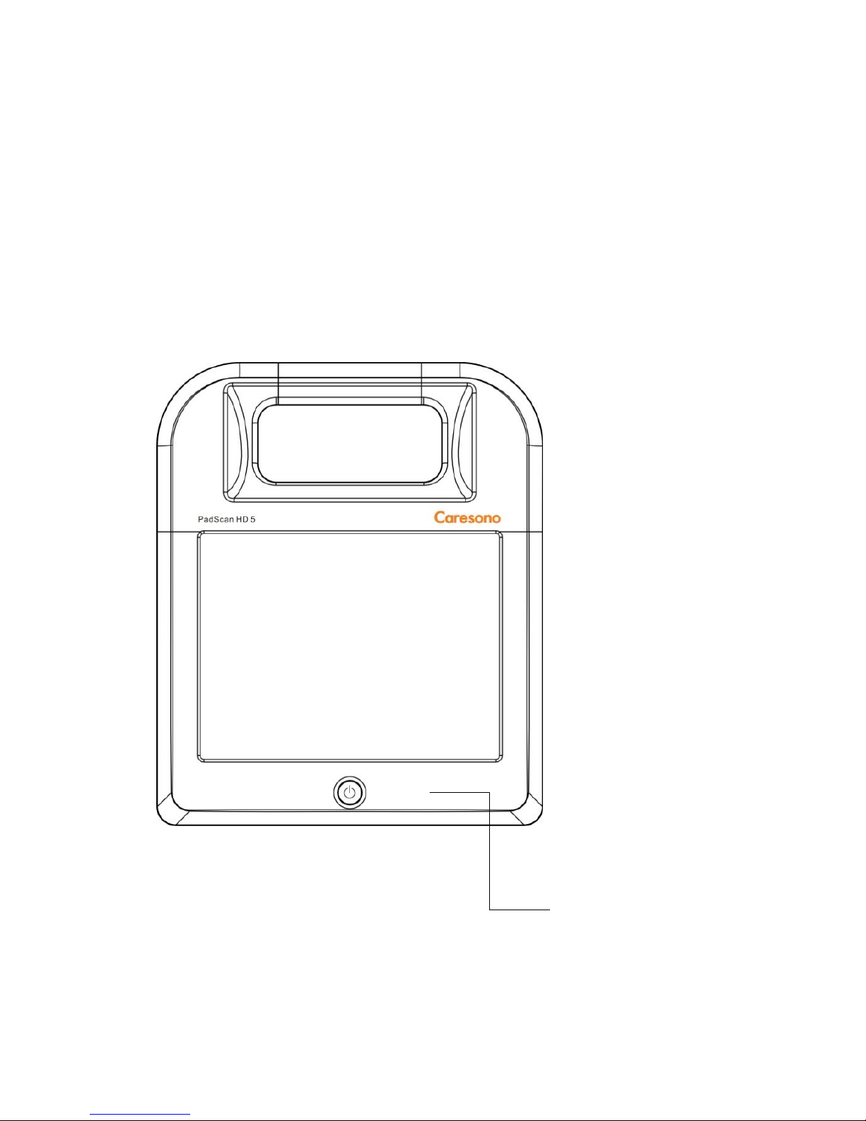
2.1.1 The appearance view of the main unit..................................................5
2.1.2The exploded drawing of the complete machine……………………...6
2.1.3 The base assembly ................................................................................7
2.2 DISASSEMBLY..............................................................................................7
2.2.1 Disassembly of the main unit................................................................7
2.2.2 Disassembly of the main board and the printer ....................................8
2.2.3Disassembly of the front coever part ....................................................9
2.2.4Disassembly of the base ......................................................................10
2.2.5 Disassembly of the power board.........................................................10
CHAPTER3 DESCRIPTION OF THE PRINCIPLE..................................................12
3.1 THE PRINCIPLE OF THE HARDWARE ...................................................11
3.1.1 The connection diagram between the main board and boards............12
3.1.2 The main board(HD-PG V-1.4).......................................................13
3.1.3 U disk interface board (HD-PG-JK1.0)…………………………18
3.1.4 Display screen signal switching driver board(HD-LED POWER V1.2)
......................................................................................................................19
3.1.5 Power switch key board(HD-DG-FJ-01A) ......................................19
3.1.6 Power socket board(HD-DG-FJ-02) ................................................19
3.1.7 Battery interface board(HD-DG-FJ-04A).....................................20
3.1.8 Touch screen driver interface board(SLT-TP05-RS232B).............20
3.1.9 Printer interface driver board(OEM SS205)..................................20
3.1.10 Display screen………………. ........................................................21
3.1.11 Touch screen......................................................................................21

ix
3.1.12 Probe.................................................................................................21
3.1.13 Printer................................................................................................21
3.1.14 Base...................................................................................................21
3.1.15 The description of the hardware .......................................................22
CHAPTER4 TROUBLESHOOTING .........................................................................28
4.1 Can not power on or power off…………………..…………………………28
4.2 No image display…………………………………………………………..29
4.3 No Response from the touch screen……………………………………….. 30
4.4 Can not measure the volume…......................................................................30
4.5Printer can not print ........................................................................................31
4.6 U disk can not work or data can not be uploaded..........................................31
CHAPTER5 MAINTENANCE AND CLEANING....................................................33
5.1 MAINTENANCE TO BE PERFORMED BY USER...................................33
5.1.1 Cleaning the system............................................................................33
5.2 MAINTENANCE TO BE PERFORMED BY SERVICE PERSONNEL ....33

1
Chapter1 General Description
1.1 Introduction
The Pad Scan HD 5 is a device that applies ultrasonic imaging and measure theory
and provides non-invasive volume measurement of the bladder. Pad scan adopt 3D
Mechanical sector scanning probe to proceed with ultrasonic scan of the bladder,
and translate the scanned information of the bladder into many 2D type B
ultrasonic images, acquired many cross-sectional area of the bladder after
complicated image processing and projected to be 3D image, finally figured out the
volume of the bladder by complicated calculation.
1. Front view
Power indicator
Power key
Figure1-1 Front view

2
2. Rear view
Figure 1-2 Rear view
3. Right view
power interface USB interface probe interface
Figure 1-3 right view

3
4. Bottom view
Charging interface air inlet
Figure 1-4 bottom view
1.2 Preparation for Repair
The needed tools and measurement devices are shown as followed:
Table 1-1 Tools and Devices for Repair
Tool
Model
Manufacturer
Spec./Standard
Screwdriver (various sizes and
types)
Unspecified
Welding iron and stand
Unspecified
Welding tool
Unspecified
Tweezers
Unspecified
Table 1-2 Consumable Material
Consumable Material
Model
Manufacturer
Spec./Standard
Insulation tape
Unspecified
Hishilite tube, Isolated tube
(various types)
Unspecified
Wires (various types)
Unspecified
Screws, nuts, washers
(various types)
Unspecified
Solder
Paper file (various types)
Ethanol for cleaning and

4
disinfection
1.3Schematic Diagram
Figure 1-5 Schematic Diagrams

5
Chapter2 Structure of the Complete Machine &
Disassembly
2.1 Structure of the Complete Machine
2.1.1 The appearance view of the main unit
Figure 2-1 the appearance view of the main unit
2.1.2 The exploded drawing of the complete machine
2.1.2.1 The exploded drawing of the complete machine

6
Figure 2-2 the exploded drawing of the complete machine
2.1.2.2 Parts of each assembly
1. Front cover
2. Touch screen
3. LCD SCREEN
4. LCD screen fixing board
5. Print driver board
6. touch screen driver board
7. the main board
8. printer fixing frame
9.printer
10.interface board
11. rear cover
12. probe cup
13.battery
14.battery buckle
15. LCD driver board
16.power key

7
2.1.3 The base assembly
2.1.3.1Assembly and outline drawing of the base
Figure 2-3 assembly drawing of base(1)
2.2 Disassembly
2.2.1 Disassembly of the main unit
1. Power on the mainframe

8
Figure 2-4 the disassembling drawing of the mainframe
A. Remove the six M3*15 fixing screws of the rear cover
B. Apart the front cover and rear cover, remove the associated lines,as figure 2-5
Figure 2-5 the disassembling drawing of the mainframe
2.2.2. Disassembly of the main board and printer
Figure 2-6 the disassembling drawing of the main board and printer
1.Two m3x5 self-tapping screws
1
2
3

9
2.Four m3x8 self-tapping screws
3.Two m3x8 self-tapping screws,two m2.5x8 self-tapping screws,two m3x8
mechanical screws
A. Before disassembling the main board, first remove the nuts outside the probe
connector, and then remove six screws as shown in the figure.
B. Remove the four m3x8 fixing screws, and then take out the printer and the printer
driver board.
2.2.3 Disassembly of the front cover
Figure 2-7 Disassembly of the front cover
A. Remove the four M3x8 fixing screws
B. Unplug the connection line between the touch screen driver board and touch screen,
unplug the connection line between the display conversion board and the LCD screen,
and then you can remove the display screen and the touch screen.
C. remove the two M3x8 screws, then remove the key board and the keys.
1
2

10
2.2.4 Disassembly of the base
Figure 2-8 the bottom of the base
A.Remove the four cushions, and then remove four m3x28 locking screws
2.2.5 Disassembly of the power board
Figure 2- Disassembly drawing of the power board

11
A. take out the power supply board by uplifting the PCB board from the side of power
input connector.
B. then weld the line of power supply board
Other manuals for PadScan HD 5
1
Table of contents
Other Caresono Scanner manuals