Carmanah E Series User manual

E / F / G Series
POLARA iNX/iDX RETROFIT GUIDE
Carmanah Technologies Corp. | 250 Bay St, Victoria, BC V9A 3K5, Canada | 1.250.380.0052 | customersupport@carmanah.com | carmanah.com
For all pedestrian pushbutton-activated E/F/G Series
and legacy R920 / SC315 RRFB systems
89525_RETROFIT-GUIDE_Polara-iNX-iDX_RevB

Carmanah Technologies Corp. | 250 Bay St, Victoria, BC V9A 3K5, Canada | 1.250.380.0052 | customersupport@carmanah.com | carmanah.com 2
POLARA INX/IDX RETROFIT GUIDE
Table of Contents
1.0 Warnings and Precautions ................................................................................................................................3
1.1 Warranty Disclaimer ...................................................................................................................................3
1.2 Standards ...................................................................................................................................................3
1.3 Safety and Usage Precautions ...................................................................................................................3
2.0 Introduction.........................................................................................................................................................5
2.1 About the Polara iNX ..................................................................................................................................5
2.2 Theory of Operation....................................................................................................................................5
3.0 Available Kits and Included Components........................................................................................................6
4.0 Supported Systems and Firmware Check .......................................................................................................7
4.1 General Notes.............................................................................................................................................8
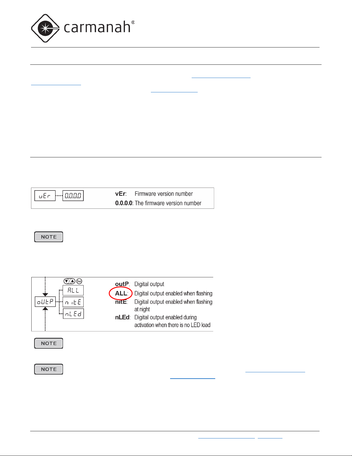
4.2 Onboard User Interface – Key Menu Items ................................................................................................8
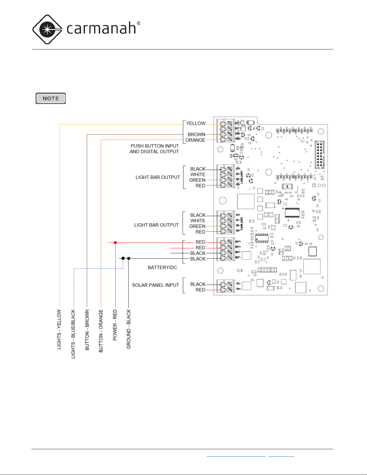
5.0 System Connectivity ..........................................................................................................................................9
6.0 Installation Procedure – Legacy Systems .................................................................................................... 11
6.1 Legacy R920 – Replacing Polara Bulldog Button ................................................................................... 11
6.2 Legacy SC315 – Replacing Polara Bulldog Button ................................................................................. 13
6.3 Legacy SC315 – Replacing Polara Model-X Button................................................................................ 16
7.0 Installation Procedure – R920-E Series......................................................................................................... 20
8.0 Installation Procedure – R920-F Series ......................................................................................................... 22
9.0 R920-F – Replacing Polara Model-X Button.................................................................................................. 24
10.0 Installation Procedure – G Series ................................................................................................................ 26
10.1 SC315-G – Replacing Polara Bulldog Button.......................................................................................... 26
10.2 SC315-G – Replacing Polara Model-X Button ........................................................................................ 28
Appendix – Basic Pushbutton Configuration..................................................................................................... 30

Carmanah Technologies Corp. | 250 Bay St, Victoria, BC V9A 3K5, Canada | 1.250.380.0052 | customersupport@carmanah.com | carmanah.com 3
POLARA INX/IDX RETROFIT GUIDE
1.0 Warnings and Precautions
The following symbols indicate important safety warnings and precautions throughout this guide:
WARNING indicates that serious bodily harm or death may result from failure to adhere to the
precautions.
CAUTION indicates that damage to equipment may result if the instructions are not followed.
NOTE suggests optimal conditions and provides additional information.
1.1 Warranty Disclaimer
This guide will familiarize you with the features and installation of the Polara iNX pedestrian pushbutton as a
retrofit into a compatible Carmanah system. Failure to comply with the use, storage, maintenance, installation or
placement instructions detailed in this guide could void the warranty.
1.2 Standards
Perform all installation, wiring, grounding and maintenance in conformance with local building and electrical
codes. Adherence to the National Electrical Code (NEC) is mandatory to comply with any certification markings.
Non-adherence to code may void the warranty.
1.3 Safety and Usage Precautions
Use extreme caution when handling the batteries as they can generate hazardous short-circuit
currents. Remove all jewelry (bracelets, metal-strap watches, etc.) before entering the cabinet.
Before lifting any heavy or bulky equipment, ensure the load is secured so moving parts do not
shift, and that it can be lifted as far as needed without back strain or loss of grip. Installation may
require more than one person.
Ensure the equipment is not powered during installation and wiring of the system.
Recheck all completed wiring for proper polarity prior to energizing the system.

Carmanah Technologies Corp. | 250 Bay St, Victoria, BC V9A 3K5, Canada | 1.250.380.0052 | customersupport@carmanah.com | carmanah.com 4
POLARA INX/IDX RETROFIT GUIDE
Changes or modifications to Carmanah equipment not expressly approved by Carmanah could
void both the user's authority to operate the equipment and the warranty.
All Carmanah traffic products use a constant-current LED output circuit. Not all traffic beacons
are compatible with this output. Please contact Carmanah for additional information and guidance
when adding or replacing beacons or other hardware.
Visit support.carmanah.com to download the complete product user manual for your specific
system.
Circuit boards are sensitive to electrostatic discharges (ESD). Care should be taken when
handling electronics to prevent discharges. Use of an ESD wrist strap and connection to cabinet
ground is recommended.
This guide is specific to retrofitting the Polara iNX/iDX with an applicable crosswalk system and is not a
replacement for the complete E/F/G Series product user manuals.

Carmanah Technologies Corp. | 250 Bay St, Victoria, BC V9A 3K5, Canada | 1.250.380.0052 | customersupport@carmanah.com | carmanah.com 5
POLARA INX/IDX RETROFIT GUIDE
2.0 Introduction
2.1 About the Polara iNX
iNX is the next generation of crosswalk accessibility, wireless connectivity and communication. iNX is designed
for rectangular rapid flashing beacons (RRFB) and other approved flashing pedestrian crosswalk systems. It
replaces Model-X and sets a new standard for pedestrian crosswalks with more features such as Bluetooth® 5
providing more speed, range and app capabilities.
The iNX provides an instructional sign, a pushbutton with directional arrow for activating the flashing lights, a
voice message, and a yellow LED which flashes upon actuation and continues to flash while the beacons are
active.
2.2 Theory of Operation
Polara APS products for use on mid-block RRFB crosswalks use a control signal provided by the flash controller
to trigger the voice message. For Carmanah systems using the older “Model-X” series products, this control signal
was provided by the LED driver output. On newer Carmanah systems, using the new iNX/iDX products, this
control signal is provided by a dedicated digital output from the flash controller (EMS). Older Carmanah
controllers did not have this dedicated output and are not compatible with the iNX/iDX series pushbuttons. This
document describes the process for changing out the Carmanah controller to the new version across several
Carmanah product models.

Carmanah Technologies Corp. | 250 Bay St, Victoria, BC V9A 3K5, Canada | 1.250.380.0052 | customersupport@carmanah.com | carmanah.com 6
POLARA INX/IDX RETROFIT GUIDE
3.0 Available Kits and Included Components
The R920 Polara iNX with EMS* retrofit kit includes:
•EMS (control board) with aluminum cover (1)
•Cable ties (4)
The R920-E/F Polara iNX retrofit kit includes:
•EMS (control board)
•Cable ties (4)
The SC315 Polara iNX with EMS retrofit kit includes:
•EMS (control board) (1)
•Security bit (1)
•#8-32 stainless steel nut (4)
•Coaxial cable extension (1)
•12” Red 18AWG wire (1)
•Cable ties (4)
The SC315-G Polara iNX retrofit kit includes:
•EMS (control board) (1)
•Cable ties (4)
*EMS = Energy Management System – System controller PCBA

Carmanah Technologies Corp. | 250 Bay St, Victoria, BC V9A 3K5, Canada | 1.250.380.0052 | customersupport@carmanah.com | carmanah.com 7
POLARA INX/IDX RETROFIT GUIDE
4.0 Supported Systems and Firmware Check
This guide details how to install the Polara iNX retrofit kit into one of the following compatible Carmanah systems:
System Model1
Product
Image
Existing
Pushbutton
Minimum EMS
Firmware Required
2
New Pushbutton
Harness Needed
R920
Polara Bulldog 1.1.5.0 Yes
SC3153
(Single EMS only)
Polara Bulldog
Polara Model X 1.1.5.0 Yes
R920-E
Polara Bulldog 1.1.5.0 Yes
R920-F
Polara Bulldog
Polara Model X 1.1.5.0 Yes
SC315-G4
Polara Bulldog
Polara Model X 1.1.5.0 Yes
1Not all legacy systems or configurations may be compatible.
2There is a wide range of firmware versions that have been deployed over several hardware releases.
Version 1.1.5.0 is for systems that are able to change the input type, “INPT”, between these options: NO, NC, BTTN.
3Single EMS version only, AC or solar powered.
4Single or dual EMS version, AC or solar powered.
•EMS = Energy Management System (circuit board assembly).
•EMS firmware is not field upgradable.

Carmanah Technologies Corp. | 250 Bay St, Victoria, BC V9A 3K5, Canada | 1.250.380.0052 | customersupport@carmanah.com | carmanah.com 8
POLARA INX/IDX RETROFIT GUIDE
4.1 General Notes
Refer to the applicable product user manual for more details at support.carmanah.com. Prior to installation, a
Solar Power Report must be provided to verify system sustainability with the addition of the iNX pushbutton. If you
have not received a solar power report, please contact Carmanah.
If your existing Energy Management System (EMS) is not running the firmware version 1.1.5.0 or greater, you will
require a new EMS as part of your retrofit kit.
Refer to the appropriate installation section based on your existing system model and pushbutton configuration.
Model iNX is equivalent to iDX in all aspects. Anywhere iNX is used in this manual, will apply to iDX also. Refer to
the respective full user manuals for additional user settings that may apply.
4.2 Onboard User Interface – Key Menu Items
Firmware Version:
Use the up/down arrows to navigate to the indicated menu item.
The Firmware Version menu item provides the current version of firmware in the EMS.
Firmware versions cannot be updated in the field.
Digital Output:
Use the up/down arrows to navigate to the indicated menu item. Hold Set to edit.
The Digital Output on the Energy Management System (EMS) must be set to ALL when used
with the iNX pushbutton on standard systems.
For systems with no installed fixture, the Digital Output must be set to nLED. This function
requires the EMS to have firmware version 1.1.5.0 or newer. Check 4.0 Supported Systems for
instructions on how to check the EMS Firmware Version.

Carmanah Technologies Corp. | 250 Bay St, Victoria, BC V9A 3K5, Canada | 1.250.380.0052 | customersupport@carmanah.com | carmanah.com 9
POLARA INX/IDX RETROFIT GUIDE
5.0 System Connectivity
1. Connectivity Overview – Standard Pushbutton:
The following diagram illustrates standard connectivity for an RRFB product configuration using a standard (non-
APS) 2-conductor pushbutton.
For AC configurations or single battery systems, only a single RED/BLACK DC power
connection will be present.
Energy Management System (EMS) PCBA

Carmanah Technologies Corp. | 250 Bay St, Victoria, BC V9A 3K5, Canada | 1.250.380.0052 | customersupport@carmanah.com | carmanah.com 10
POLARA INX/IDX RETROFIT GUIDE
2. Connectivity Overview – iNX or iDX Configuration:
The following diagram illustrates connectivity for an RRFB product configuration using an iNX or iDX 6-conductor
APS.
For AC configurations or single battery systems, only a single RED/BLACK DC power
connection will be present.
Energy Management System (EMS) PCBA

Carmanah Technologies Corp. | 250 Bay St, Victoria, BC V9A 3K5, Canada | 1.250.380.0052 | customersupport@carmanah.com | carmanah.com 11
POLARA INX/IDX RETROFIT GUIDE
6.0 Installation Procedure – Legacy Systems
6.1 Legacy R920 – Replacing Polara Bulldog Button
1. De-energize system by disconnecting both system fuses.
2. Remove 4 screws securing EMS cover.
3. Rotate EMS cover to expose EMS PCBA and wiring. Remove cable ties as required.
4. Remove the RF connector at the SMA connector on the radio module. A 5/16" open end wrench may be
required.
5. Disconnect existing pushbutton, light bar(s), beacons, or LED signs, batteries and solar panel.
Photograph or take careful note of all existing connections on EMS.
6. Remove existing EMS PCBA.
The light pipe at the top off the PCB assembly can be damaged during the removal of the EMS.
Lift the EMS gently from the bottom edge and slide down before lifting up and out of enclosure.
7. Install replacement EMS PCBA with aluminum cover provided with retrofit kit.
8. Reconnect antenna lead.
9. Route iNX cable through the large opening on the lower front edge of the EMS cover.
10. Splice Battery (+) and Battery (-) along with the BLUE/BLACK conductor into the connectors on the iNX
harness.
11. Insert the ORANGE, BROWN and YELLOW conductors as shown below:

Carmanah Technologies Corp. | 250 Bay St, Victoria, BC V9A 3K5, Canada | 1.250.380.0052 | customersupport@carmanah.com | carmanah.com 12
POLARA INX/IDX RETROFIT GUIDE
12. Reconnect light bar(s) or other LED fixtures, and solar panel.
13. Reinstall EMS cover.
14. Land iNX conductors in the appropriate locations on the pushbutton.
15. Re-energize the system.
16. Configure the pushbutton.
Pushbutton configuration can only be performed using the Polara Field Service App.
The Polara Field Service App is available for Android™ and iOS®and can be downloaded free-of-charge from the
Google Play Store or Apple App Store.
*See appendix for information on pushbutton configuration.

Carmanah Technologies Corp. | 250 Bay St, Victoria, BC V9A 3K5, Canada | 1.250.380.0052 | customersupport@carmanah.com | carmanah.com 13
POLARA INX/IDX RETROFIT GUIDE
6.2 Legacy SC315 – Replacing Polara Bulldog Button
The following section applies to legacy SC315 systems with either DIN rail mounted terminal blocks, or screw-
type terminal blocks and equipped with a pre-existing Polar Bulldog pushbutton.
DIN rail version Screw-type terminal blocks
1. Confirm power is removed from the system. Remove fuses or turn AC breaker off. Shield solar panel with
an opaque covering to effectively de-energize the panel.
2. Remove four screws with included pin-in-hex adapter from the back of the cabinet that secure the EMS
mounting plate.
The screws can start to spin easily. Apply pressure to the front of the EMS opposite the screw
being removed. This will help prevent the stand-off part inside the cabinet from spinning.
A nut driver can be used for lower screws. Apply pressure on the front of the EMS for upper
screws.
3. Carefully flip the EMS mounting plate around, cutting cable ties securing the radio module in place.
4. Remove the RF connector at the SMA connector on the radio module. A 5/16" open end wrench may be
required.
5. Disconnect existing pushbutton, light bar(s), beacons, or LED signs, batteries and solar panel (if
applicable).

Carmanah Technologies Corp. | 250 Bay St, Victoria, BC V9A 3K5, Canada | 1.250.380.0052 | customersupport@carmanah.com | carmanah.com 14
POLARA INX/IDX RETROFIT GUIDE
Photograph or take careful note of all existing connections on EMS.
6. Install replacement EMS PCBA provided with retrofit kit.
7. Reconnect antenna lead.
8. Route iNX conductors through the large opening on the lower front edge of the EMS cover.
9. Insert the RED wire from the iNX harness into the 4-postion terminal block (see image below).
10. Using the WAGO connector provided, splice the iNX BLACK wire and BLUE/BLACK wires.
11. Use a short length of BLACK wire to make the connection between the WAGO connector and the 4-
position terminal block on the circuit board (see image below).
12. Insert the ORANGE, BROWN and YELLOW conductors as shown below.
13. Reconnect the light bar(s) or other LED fixtures and solar panel (if applicable).
Completed internal iNX connections (solar panel connection not shown)
14. Reinstall the EMS chassis into the cabinet.

Carmanah Technologies Corp. | 250 Bay St, Victoria, BC V9A 3K5, Canada | 1.250.380.0052 | customersupport@carmanah.com | carmanah.com 15
POLARA INX/IDX RETROFIT GUIDE
15. Use a cable tie to secure the iNX cable jacket to the EMS cover.
16. Land iNX conductors in the appropriate locations on the pushbutton.
17. Re-energize the system.
18. Configure the pushbutton.
Pushbutton configuration can only be performed using the Polara Field Service App.
The Polara Field Service App is available for Android and iOS and can be downloaded free-of-charge from the
Google Play Store or Apple App Store.
*See appendix for information on pushbutton configuration.

Carmanah Technologies Corp. | 250 Bay St, Victoria, BC V9A 3K5, Canada | 1.250.380.0052 | customersupport@carmanah.com | carmanah.com 16
POLARA INX/IDX RETROFIT GUIDE
6.3 Legacy SC315 – Replacing Polara Model-X Button
Overview
For systems using the Polara Model-X pushbuttons and the separate XAV control board, the control signal for
activating the voice message is provided by a voltage on the RRFB light bar circuit. For systems using the
iNX/iDX, this control signal now is produced by a digital output on the Carmanah EMS, labelled “EXT 2” on the
EMS circuit board (see schematic in Section 5.0).
The following section applies to legacy SC315 systems with either DIN rail mounted terminal blocks, or screw-
type terminal blocks and equipped with a pre-existing Polara Model X pushbutton and XAV pushbutton control
board.
Model X with DIN rail terminal blocks Model X with screw-type terminal blocks
1. Confirm power is removed from the system. Remove fuses or turn AC breaker off. Shield solar panel with
an opaque covering to effectively de-energize the panel.
Removal of existing XAV control board is optional; however, all connections to the XAV control
board to the system should be removed, including DC power.
2. Remove the 4 screws securing the XAV controller from the outside left of the cabinet. Use included pin-in-
hex bit and save the screws to be re-installed.
Ensure the O-ring washers stay in place on the 4 sealing screws.
3. Remove the XAV controller from the inside left of cabinet. Remove cable ties to remove harness.

Carmanah Technologies Corp. | 250 Bay St, Victoria, BC V9A 3K5, Canada | 1.250.380.0052 | customersupport@carmanah.com | carmanah.com 17
POLARA INX/IDX RETROFIT GUIDE
4. Re-install 4 screws that held the XAV controller in place on the side of the cabinet. Use four 8-32 lock
nuts provided. Nuts should be installed inside cabinet.
5. Remove four screws with included pin-in-hex adapter from the back of the cabinet that secure the EMS
mounting plate.
The screws can start to spin easily. Apply pressure to the front of the EMS opposite the screw
being removed. This will help prevent the stand-off part inside the cabinet from spinning.
A nut driver can be used for lower screws. Apply pressure on the front of the EMS for upper
screws.
6. Carefully flip the EMS mounting plate around, cutting cable ties securing the radio module in place.
7. Remove the RF connector at the SMA connector on the radio module. A 5/16" open end wrench may be
required.
8. Disconnect existing pushbutton, light bar(s), beacons, or LED signs, batteries and solar panel (if
applicable).
Leave existing connections at the terminal blocks on the outside of the EMS cover. This applies
to both DIN rail and screw-type terminal block configurations.
XAV Controller

Carmanah Technologies Corp. | 250 Bay St, Victoria, BC V9A 3K5, Canada | 1.250.380.0052 | customersupport@carmanah.com | carmanah.com 18
POLARA INX/IDX RETROFIT GUIDE
Photograph or take careful note of all existing connections on EMS.
For this product configuration, the pre-existing connection that uses the YELLOW wire to
connect the light bar output to the XAV control board will not be reused. This applies to both DIN
rail and screw-type terminal block configurations.
9. Install replacement EMS PCBA provided with retrofit kit.
10. Reconnect antenna lead.
11. Route iNX conductors through the large opening on the lower front edge of the EMS cover.
12. Insert the RED wire from the iNX harness into the 4-postion terminal block (see image below).
13. Using the WAGO connector provided, splice the iNX BLACK wire and BLUE/BLACK wires.
14. Use a short length of BLACK wire to make the connection between the WAGO connector and the 4-
position terminal block on the circuit board (see image below).
15. Insert the ORANGE, BROWN and YELLOW conductors as shown below.
16. Use a short length of RED wire to replace the missing light bar conductor (previously YELLOW).
17. Reconnect the light bars or other LED fixtures and solar panel (if applicable).
Completed internal iNX connections (solar panel connection not shown)
18. Reinstall the EMS chassis into the cabinet.

Carmanah Technologies Corp. | 250 Bay St, Victoria, BC V9A 3K5, Canada | 1.250.380.0052 | customersupport@carmanah.com | carmanah.com 19
POLARA INX/IDX RETROFIT GUIDE
19. Use a cable tie to secure the iNX cable jacket to the EMS cover.
20. Land iNX conductors in the appropriate locations on the pushbutton.
21. Re-energize the system.
22. Configure the pushbutton.
Pushbutton configuration can only be performed using the Polara Field Service App.
The Polara Field Service App is available for Android and iOS and can be downloaded free-of-charge from the
Google Play Store or Apple App Store.
*See appendix for information on pushbutton configuration.

Carmanah Technologies Corp. | 250 Bay St, Victoria, BC V9A 3K5, Canada | 1.250.380.0052 | customersupport@carmanah.com | carmanah.com 20
POLARA INX/IDX RETROFIT GUIDE
7.0 Installation Procedure – R920-E Series
1. De-energize system by disconnecting both system fuses.
2. Remove 4 screws securing EMS cover.
3. Rotate EMS cover to expose EMS PCBA and wiring. Remove cable ties as required.
For systems that have firmware version 1.1.5.0 already installed, replacement of the PCBA is
not required. Skip to step number 9 in this section.
4. Remove the RF connector at the SMA connector on the radio module. A 5/16" open end wrench may be
required.
5. Disconnect existing pushbutton, light bar(s), beacons, or LED signs, batteries and solar panel.
Photograph or take careful note of all existing connections on EMS
6. Remove existing EMS PCBA.
The light pipe at the top off the PCB assembly can be damaged during the removal of the EMS.
Lift the EMS gently from the bottom edge and slide down before lifting up and out of enclosure.
7. Install replacement EMS PCBA provided with retrofit kit.
8. Reconnect antenna lead.
9. Route iNX cable through the large opening on the lower front edge of the EMS cover.
10. Splice Battery (+) and Battery (-) along with the BLUE/BLACK conductor into the connectors on the iNX
harness.
Other manuals for E Series
9
This manual suits for next models
4
Table of contents
Other Carmanah Safety Equipment manuals