Reliance Roto-Loc 44 Series User manual

INSTRUCTIONS FOR USE
44XXXXX Series Roto-Loc™
Self Retracting Lanyards
Phone : 281-930-8000
Toll Free : 888-362-2826
Fax : 281-930-8666
Complies with the current ANSI Z359.14-2014 and all
applicable OSHA regulations and requirements.
Reliance Industries
P.O. Box 2046
Deer Park, TX 77536

Page 2
Contents
DESCRIPTION 3 - 5
PRODUCT SPECIFICATIONS 6
APPLICATION 6
A. PURPOSE ....................................................................................................................6
1) PERSONAL FALL ARREST..................................................................................6
B. USE LIMITATIONS .......................................................................................................7
1) CAPACITY ...........................................................................................................7
2) FREE FALL ..........................................................................................................7
3) FALL CLEARANCE ...................................................................................... 8 - 10
4) SWING PENDULUM FALLS .............................................................................10
5) CHEMICAL HAZARDS .......................................................................................11
6) HEAT...................................................................................................................11
7) CORROSION......................................................................................................11
8) ELECTRICAL HAZARDS....................................................................................11
9) MOVING MACHINERY.......................................................................................11
10) SHARP EDGES AND ABRASIVE SURFACES ..................................................12
11) WEAR AND DETERIORATION...........................................................................12
12) IMPACT FORCES...............................................................................................12
SYSTEMS REQUIREMENTS 12
A. COMPATIBILITY OF SYSTEM PARTS......................................................................12
1) COMPATIBILITY OF COMPONENTS AND SUBSYSTEMS ................................12
2) COMPATIBILITY OF CONNECTORS...................................................................13
3) ANCHORAGES AND ANCHORAGE CONNECTORS..........................................13
INSTALLATION PROCEDURE 14
A. CONNECTING THE SRL TO AN ANCHOR POINT ..................................................14
B. CONNECTING THE SRL TO A HARNESS ..................................................... 14 - 15
C. PREPARATION FOR USE .......................................................................................15
D. INSPECT PRIOR TO USE .........................................................................................16
E. PLAN SCOPE OF WORK TO BE PERFORMED ANALYSIS) .......................... 16 - 18
CARE OF THE ROTO-LOC 18
INSPECTIONS 18
A. INSPECTION FREQUENCY ......................................................................................18
B. INSPECTION PROCEDURE.............................................................................. 19 - 20
TRAINING 20
RESCUE PLANNING 20 - 21
SERVICING 21
GUARDING AGAINST APPLICATION FAILURE 21
WARNINGS AND LIMITATIONS 22
LABELING 23 - 24
NOTES 25
INSPECTION RECORD 26
PART NUMBER LIST 27
WARRANTY STATEMENT 27

Instructions for Use
Page 3
User Instructions
Reliance Self Retracting Lanyards
User Instruction Manual - Self Retracting Lanyards
This manual is intended to meet the Manufacturer’s Instructions as required by
the current ANSI Z359.14-2014 ,and should used as part of an employee training
program as required by OSHA.
WARNING
This product is one part of a personal fall arrest, restraint, work positioning, personnel riding,
climbing, or rescue system. Without the other necessary components in such sub-systems
the Self Retracting Lanyard itself serves no useful purpose. The user must follow the manu-
facturer’s instructions for each component of the system. These instructions must be pro-
vided to the user before using this product and retained for ready reference by the user. The
user must read, understand (or have explained), and heed all instructions, labels, markings
and warnings supplied with this product and with those products intended for use in asso-
ciation with it before using this equipment. Manufacturer’s instructions must be followed for
proper use and maintenance of this equipment. National standards and state, provincial and
federal laws require the user to be trained before using this product. This manual can be used
as part of a such a user safety-training program that is appropriate for the user’s occupation.
IMPORTANT: Alterations or misuse of this product or failure to follow in-
structions may result in serious injury or death. If you have questions on the
use, care, or suitability of this equipment for your application, contact RELIANCE
Fall Protection for information.
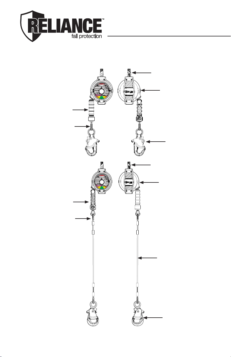
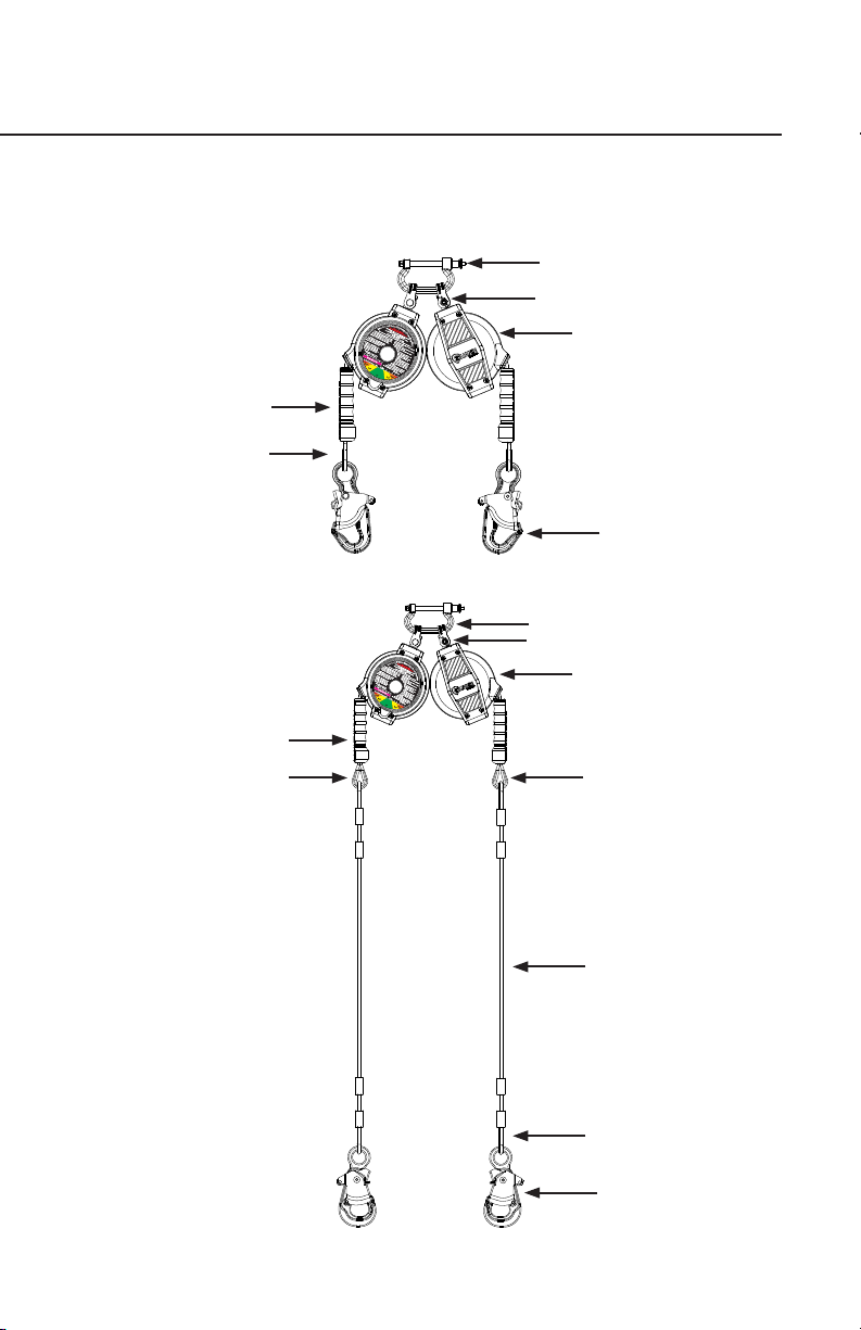
DESCRIPTION
The Roto-Loc™ Leading Edge Self Retracting Lanyard (SRL-LE) is designed to
be a component in a personal fall arrest systems (PFAS). It may be used in most
situations where a combination of worker mobility and fall protection is required
(i.e. inspection work, general construction, maintenance work, steel stick work,
etc.). The Roto-Loc™ SRL-LE is designed for use by a single person weighing
up to 310 lbs [141kg] (body weight plus tools) Roto- Loc™ Leading Edge Self Re-
tracting Lanyard features a cam-action Stop-Cap Pawl system ensuring positive
lock-up even in the most demanding environments. The SRL-LE’s are mounted
at the dorsal D-ring location of the users full body harness. Models are available
in both single and twin SRL- LE congurations which incorporate both Pelican™
and Rebar snap hooks. The unique hook body design’s prevent the accidental
“false engagement” to the anchorage structure or D-ring, while the case swivel
provides an easy to see load indicator showing whether the Roto-Loc™ Leading
Edge Self Retracting Lanyard has been exposed to a fall arrest load and needs
to be serviced.

Page 4
Identifying Components of Roto-Loc™
Leading Edge Single Self Retracting Lanyards
Figure 1 - Single
4485006-1, 4486006-1, 4487006-1, 4480006-1
Figure 1A -
Single Tie-Back
Housing
Load Indicating
Swivel
Snap Hook
EZ Grip Cable Pull
Thimble Eye
Housing
Load Indicating
Swivel
Snap Hook
EZ Grip Cable Pull
Thimble Eye
Blue Coated
Tie-Back Cable

Instructions for Use
Page 5
Figure 2 - Twin
4495006-1, 4496006-1, 4497006-1, 4490006-1
Load Indicating
Swivel
Identifying Components of Roto-Loc™
Leading Edge Twin Self Retracting Lanyards
Figure 2A -
Twin Tie-Back
3020 Connector Bracket
Housing
EZ Grip Cable Pull
Thimble Eye
Snap Hook
Load Indicating Swivel
3020 Connector Bracket
Housing
EZ Grip Cable Pull
Thimble Eye
Snap Hook
Thimble Eye
Thimble Eye
Blue Coated
Tie-Back Cable

Page 6
PRODUCT SPECIFICATIONS
Part # Working
Length Line Type Weight SRL Type Hook Type Housing
Type
Housing
Dimensions
4485006-1 6' (1.8m) 3/16" (4.5mm)
Galvanized 4.9 Single 3006WR Pelican
ZN Plate
Sanoprene over
ABS
8"Lx5"Wx3.5"H
(20.3cmX12.7cmX88.9cm)
4486006-1 6' (1.8m) 3/16" (4.5mm)
Galvanized 5.6 Single 3011WR Rebar
ZN Plate
Sanoprene over
ABS
8"Lx5"Wx3.5"H
(20.3cmX12.7cmX88.9cm)
4487006-1 6' (1.8m) 3/16" (4.5mm)
Galvanized 5.1 Single Tie-Back w/
Steelhead ZN Plate
Sanoprene over
ABS
8"Lx5"Wx3.5"H
(20.3cmX12.7cmX88.9cm)
4480006-1 6' (1.8m) 3/16" (4.5mm)
Galvanized 5.5 Single Pelican Swivel
ZN Plate
Sanoprene over
ABS
8"Lx5"Wx3.5"H
(20.3cmX12.7cmX88.9cm)
4495006-1 6' (1.8m) 3/16" (4.5mm)
Galvanized 10.1 Twin 3006WR Pelican
ZN Plate
Sanoprene over
ABS
8"Lx5"Wx3.5"H
(20.3cmX12.7cmX88.9cm)
4495006-Z 6' (1.8m) 3/16" (4.5mm)
Galvanized 10.1 Twin 3006WR Pelican
ZN Plate
Sanoprene over
ABS
8"Lx5"Wx3.5"H
(20.3cmX12.7cmX88.9cm)
4496006-1 6' (1.8m) 3/16" (4.5mm)
Galvanized 11.5 Twin 3011WR Rebar
ZN Plate
Sanoprene over
ABS
8"Lx5"Wx3.5"H
(20.3cmX12.7cmX88.9cm)
4496006-Z 6' (1.8m) 3/16" (4.5mm)
Galvanized 11.5 Twin 3011WR Rebar
ZN Plate
Sanoprene over
ABS
8"Lx5"Wx3.5"H
(20.3cmX12.7cmX88.9cm)
4497006-1 6' (1.8m) 3/16" (4.5mm)
Galvanized 10.5 Twin
Tie-Back w/
Steelhead ZN
Plate,
Sanoprene over
ABS
8"Lx5"Wx3.5"H
(20.3cmX12.7cmX88.9cm)
4490006-1 6' (1.8m) 3/16" (4.5mm)
Galvanized 11.3 Twin Pelican Swivel
ZN Plate
Sanoprene over
ABS
8"Lx5"Wx3.5"H
(20.3cmX12.7cmX88.9cm)
LEADING EDGE SELF RETRACTING LANYARD
APPLICATION
A. PURPOSE:
RELIANCE Leading Edge Self Retracting Lanyards (SRL-LE’s) are used as
one component in a personal fall arrest system (PFAS). The SRL-LE’s de-
scribed in this manual meet, ANSI Z359.14 and OSHA requirements. These
instructions, and markings borne by the SRL-LE’s, fulll the instruction and
marking requirements of those standards and regulations. This equipment is
specically designed to dissipate fall energy and limit the fall arrest forces that
are transferred to the body. The SRL-LE can only be mounted to the users
dorsal D-Ring for Leading Edge applications.
1) PERSONAL FALL ARREST:
The Self Retracting Lanyard is used as a component of a personal fall arrest
system. Personal fall arrest systems typically include a full body harness, a
The following specications apply to all Roto-Loc™ Leading Edge Self Retracting Lanyards
and meet the Class A & SRL-LE requirements of ANSI Z359.14-2014:
• MAXIMUM ARREST FORCE (MAF): ≤ 1,800 lbs (8kN)
• AVERAGE ARREST FORCE (AAF): ≤1350lbs(6kN)
• OVERHEAD ARREST DISTANCE (AD): ≤ 24” (.6m)
• LEADING EDGE ARREST DISTANCE: See Charts to follow
• 310 LB MAX. CAPACITY : 1 worker, max. combined tool & body weight ≤ 310 lbs
(140.6kg).

Instructions for Use
Page 7
connecting subsystem (energy absorbing device such as a shock absorbing
lanyard or Self Retracting Lanyard) and an anchorage connector. Average arresting
force must not exceed 1350 lbs (1kN) for ANSI Z359.14-2014 and 1,800 lbs MAF
(8kN) for OSHA.
B. USE LIMITATIONS:
Consider the following application limitations before using this equipment:
1) CAPACITY:
These SRL’s are designed for use by persons with a combined weight (clothing,
tools, etc.) of no more than 310 lb Max. Capacity: 1 worker.
ALLOWABLE ANGLE OF REDIRECTION
FIGURE 1
WARNING
Persons with muscular, skeletal, or other physical disorders should consult a physician before
using. Pregnant women and minors must never use this equipment. Increasing age and diminished
physical tness may reduce a person’s ability to withstand shock loads during fall arrest or prolonged
suspension. Consult a physician if there is any question about a users physical ability to safely use
this product to arrest a fall or remain suspended.
2) FREE FALL:
When anchored overhead, SRL-LE’s will limit the arrest distance to 2 ft. (61cm) or
less. To avoid increased fall distances, anchor the SRL-LE directly above the work
level. Avoid working where your lanyard may cross or tangle with that of another
worker. Avoid working where an object may fall and strike the lanyard; resulting in
loss of balance or damage to the lanyard. Do not allow the lanyard to pass under
arms or between legs. Never clamp, knot, or prevent the lanyard from retracting or
being taut. Avoid slack line. Do not lengthen SRL-LE by connecting a lanyard or
similar component.
WARNING
Do not allow the Lanyard to pass under arms or between legs. Never clamp, knot, or prevent the
Lanyard from retracting or being taut. Avoid slack line. Do not lengthen the SRL by connecting a
lanyard or other components without consulting Reliance.
WARNING
Use of this device while attached to a “foot-level” anchorage or while exposed to an unprotected
structural edge should be a LAST RESORT. Every effort should be made to attach to a properly rated
overhead anchorage in an effort to reduce the overall fall distance. DO NOT allow the retractable line
to come into contact with a sharp, jagged, serrated or abrasive edge. A “foot-level” or “leading-edge”
fall is likely to result in the injury of the user – the rst hazard in the fall path is and always will be the
structural edge, itself! Elevate your anchorage to the extent possible for the best outcome.

Page 8
3) FALL CLEARANCE:
Figures 2 through 2B & 3A through 3C illustrate Fall Clearance requirements.
Ensure adequate clearance exists in the fall path to prevent striking an object
during a fall. If a user is working at a position that is not directly below the SRL-
LE anchorage point, the clearance required and vertical fall distance increase.
Figure 3A and 3C provide the clearance requirements when using the SRL-LE
for leading edge applications.
Determine Fall Clearance Required: To determine the fall clearance required,
measure the distance from the user’s harness dorsal connection to the
anchorage for the SRL-LE. Both horizontal and vertical distances are required.
Use Figures 2 through 2B & 3Athrough 3B to determine the required clearance.
The lines in the gures represent 1 foot (0.3 m) increments from the user’s
harness dorsal connection to the anchorage. For example, 12 ft of clearance is
required when the SRL-LE unit is anchored 2 ft back and 0 ft to the side of the
user’s harness dorsal connection for users up to 310 lbs (141 kg).
6' 5' 4' 3' 2' 1' 01' 2' 3' 4' 5' 6'
6' 3.0
5' 4.0 3.0 3.0 3.0 3.0 3.0 4.0
4' 4.5 4.0 3.5 3.0 3.0 3.0 3.5 4.0 4.5
3' 5.5 4.5 4.0 3.5 3.5 3.5 3.5 3.5 4.0 4.5 5.5
2' 5.5 4.5 4.5 3.5 3.5 3.5 3.5 3.5 4.5 4.5 5.5
1' 6.0 5.0 4.5 4.0 4.0 3.5 4.0 4.0 4.5 5.0 6.0
Bac k D-Ring 06.0 5.0 4.5 4.0 4.0 4.0 4.0 4.0 4.5 5.0 6.0
1' 7.0 6.5 5.5 5.5 5.0 5.0 5.0 5.5 5.5 6.5 7.0
2' 8.5 7.5 6.5 6.5 6.5 6.0 6.5 6.5 6.5 7.5 8.5
3' 9.5 8.5 8.0 7.5 7.5 7.5 7.5 7.5 8.0 8.5 9.5
4' 10.0 9.0 9.0 8.5 8.5 8.5 9.0 9.0 10.0
5' 10.0 10.0 10.0 10.0 10.0 10.0 10.0
6' 12.0
Clearance (Feet) Be twee n Worki ng Surface and Nearest Obstruction (Inc ludes SRL
Exte nsion, Fre e Fal l , 2 Foot Safety Fac tor)
Anchorage Offset From Bac k D-Ring
FI GURE 2
Anchorage Level Below
Bac k D-Ring
Anchorage Level Above
Bac k D-Ring
WARNING
The clearances provided here assume the fall occurs from a standing position. If the worker is
kneeling or crouching an additional 3 ft (0.9m) clearance is needed. Failure to heed this warning may
result in serious injury or death.
WARNING
The allowable angle of redirection of the Lanyard at the edge over which a fall might occur, measured
by the two sides formed by the redirected Lanyard must be at least 90 degrees. In other words,
working above the level at which the SRL-LE is anchored and being exposed to an edge hazard is
dangerous because this will cause the Lanyard to ‘redirect’ at a sharper angle if a fall occurs and may
cut or damage the Lanyard. In addition, do not work on the far side of an opening, opposite the SRL-
LE anchorage point. Failure to heed these warnings may result in serious injury or death.

Instructions for Use
Page 9
Tie-Back Conguration
Tie-Back Snap Hook to cable
around anchor
Tie-Back Conguration
Tie-Back Snap Hook to anchor,
direct connection
6' 5' 4' 3' 2' 1' 01' 2' 3' 4' 5' 6'
8' 3.0
7' 4.0 3.0 3.0 3.0 3.0 3.0 4.0
6' 4.5 4.0 3.5 3.0 3.0 3.0 3.5 4.0 4.5
5' 5.5 4.5 4.0 3.5 3.5 3.5 3.5 3.5 4.0 4.5 5.5
4' 5.5 4.5 4.5 3.5 3.5 3.5 3.5 3.5 4.5 4.5 5.5
3' 6.0 5.0 4.5 4.0 4.0 3.5 4.0 4.0 4.5 5.0 6.0
2' 6.0 5.0 4.5 4.0 4.0 4.0 4.0 4.0 4.5 5.0 6.0
1' 7.0 6.5 5.5 5.5 5.0 5.0 5.0 5.5 5.5 6.5 7.0
Bac k D-Ri ng 08.5 7.5 6.5 6.5 6.5 6.0 6.5 6.5 6.5 7.5 8.5
1' 9.5 8.5 8.0 7.5 7.5 7.5 7.5 7.5 8.0 8.5 9.5
2' 10.0 9.0 9.0 8.5 8.5 8.5 9.0 9.0 10.0
3' 10.0 10.0 10.0 10.0 10.0 10.0 10.0
4' 12.0
5'
6'
Clearance (Fe et) Between Working Surfac e and Nearest Obst ruction. (Includes
SRL Extension, Fre e Fall , 2 Foot Safe ty Factor)
Anchorage Offset From Bac k D-Ri ng
FI GURE 2A Tie-Bac k
Direct Connection
Anchorage Leve l Below
Bac k D-Ri ng
Anchorage Leve l Above
Bac k D-Ri ng
6' 5' 4' 3' 2' 1' 01' 2' 3' 4' 5' 6'
6' 3.0
5' 4.0 3.0 3.0 3.0 3.0 3.0 4.0
4' 4.5 4.0 3.5 3.0 3.0 3.0 3.5 4.0 4.5
3' 5.5 4.5 4.0 3.5 3.5 3.5 3.5 3.5 4.0 4.5 5.5
2' 5.5 4.5 4.5 3.5 3.5 3.5 3.5 3.5 4.5 4.5 5.5
1' 6.0 5.0 4.5 4.0 4.0 3.5 4.0 4.0 4.5 5.0 6.0
Bac k D-Ring 06.0 5.0 4.5 4.0 4.0 4.0 4.0 4.0 4.5 5.0 6.0
1' 7.0 6.5 5.5 5.5 5.0 5.0 5.0 5.5 5.5 6.5 7.0
2' 8.5 7.5 6.5 6.5 6.5 6.0 6.5 6.5 6.5 7.5 8.5
3' 9.5 8.5 8.0 7.5 7.5 7.5 7.5 7.5 8.0 8.5 9.5
4' 10.0 9.0 9.0 8.5 8.5 8.5 9.0 9.0 10.0
5' 10.0 10.0 10.0 10.0 10.0 10.0 10.0
6' 12.0
Clearance (Feet) Be twee n Worki ng Surfac e and Nearest Obstructi on (Inc l ude s
SRL Extension, Free Fal l , 2 Foot Safety Fac tor)
FIGURE 2B Tie-Ba c k
Snap Hook to Cable
around Anchor
Anchorage Offset From Bac k D-Ring
Anchorage level Above
Bac k D-Ring
Tie-Back Configuration
Tie-Back Snap Hook to Cable
around anchor
Anchorage Level Below
Bac k D-Ring

Page 10
4) SWING PENDULUM FALLS:
Swing falls occur when the anchorage point is not directly above the point
where a fall occurs (see Figure 4). The force of striking an object in a swing
fall may cause serious injury. In a swing fall, the total vertical fall distance will
be greater than if the user had fallen directly below the anchorage point, thus
increasing fall clearance required to safely arrest the user. Use Figures 2 and
3A through 3B to determine the fall clearance for your application. Minimize
swing falls by working as directly below the anchorage point as possible. Never
permit a swing fall if injury could occur.
WARNING
Do not work on the far side of an opening, opposite the SRL-LE anchorage point. Failure to heed this
warning may result in serious injury or death.
FIGURE 3B Clearance Required (A) When Falling Over an Edge
Distance Along Edge (B), ft
0 1 2 3 4 5
1 12.0 12.5 13.5 14.5 15.5
2 12.0 12.5 13.0 13.5
3 12.0 12.5 13.0 13.5
4+ 12.0 12.5
Setback
Distance (C)
WARNING!
DO NOT RIG YOUR
DEVICE IN THIS ZONE.
MAY RESULT IN INJURY OR DEATH.
FIGURE 3C
Tie-Back
Direct Connection
Clearance Required (A) When Falling Over an Edge
Distance Along Edge (B), ft
0 1 2 3 4 5
2 13.0 13.5 14.5 15.5 16.5
3 13.0 13.5 14.0 14.5
4 13.0 13.5 14.0 14.5
5+ 13.0 13.5
Setback
Distance (C)
WARNING!
DO NOT RIG YOUR
DEVICE IN THIS ZONE.
MAY RESULT IN INJURY OR DEATH.
FIGURE 3A

Instructions for Use
Page 11
FIGURE 4
RIGHT WRONG
5) CHEMICAL HAZARDS:
Acidic, alkaline, or other environments with harsh substances may
damage the webbing (if equipped) and hardware elements of this SRL.
Polyester webbing is more resistant to attack by acids, but is subject
to degradation by alkaline or neutral pH environments. If working in a
chemically aggressive environment, an SRL that uses a cable Lanyard
is generally recommended. When working in the presence of chemicals,
more frequent inspection of the SRL is required.
6) HEAT:
Do not use SRL’s that utilize a web Lanyard in environments with
temperatures greater than 185°F (85°C). Protect the lanyard when used
near welding, metal cutting, or other heat producing activities. Sparks may
damage the lanyard cable and reduce its strength.
IMPORTANT: When working with tools, materials, or in high temperature environments,
ensure that associated fall protection equipment can withstand high temperatures, or
provide protection for those items.
7) CORROSION:
Do not expose the device to corrosive environments for prolonged periods.
Organic substances and salt water are particularly corrosive to metal
parts. When working in a corrosive environment more frequent inspection,
cleaning, and drying of the SRL-LE is required. See Care and Inspection
sections for cleaning and inspection details.
8) ELECTRICAL HAZARDS:
Use extreme caution when working near energized electrical sources.
Metal hardware on the SRL, the Lanyard itself, and on other components
connected to it will conduct electric current. Maintain a safe working
distance [preferably at least 10’ (3m)] from electrical hazards.
9) MOVING MACHINERY:
When working near moving machinery parts (e.g. conveyors, rotating
shafts, presses, etc.), make sure that loose equipment is secured. Maintain

Page 12
a safe working distance from machinery that could entangle clothing, the
Lanyard, the harness, or other components connected to it.
10) SHARP EDGES AND ABRASIVE SURFACES:
Do not expose lanyards to sharp edges or abrasive surfaces that could cut,
tear, abrade, or damage the wire rope. If working around sharp edges and
abrasive surfaces is unavoidable use heavy padding or other protective
barriers to prevent direct contact. Contact Reliance before using an in-line
energy absorbing component or lanyard with an SRL.
11) WEAR AND DETERIORATION:
Any SRL-LE which shows signs of excessive wear, deterioration or aging,
must be removed from use and marked “UNUSABLE” until destroyed. See
detailed inspection procedures.
12) IMPACT FORCES:
Any SRL-LE that has been subjected to the forces of arresting a fall must
SYSTEMS REQUIREMENTS
A. COMPATIBILITY OF SYSTEM PARTS
1) COMPATIBILITY OF COMPONENTS AND SUBSYSTEMS:
RELIANCE SRL-LE’s are designed to be used with RELIANCE approved
components and connecting subsystems. Use of the SRL-LE with products
made by others should be evaluated by a competent person to ensure
compatibility of components and hardware. Connecting subsystems must
be suitable for use in the application (e.g. fall arrest or restraint). RELIANCE
manufactures a line of connecting subsystems for most applications. Contact
RELIANCE for further information. Refer to the manufacturer’s instructions
supplied with the component or connecting subsystem to determine suitability.
Contact RELIANCE with any questions regarding compatibility of equipment
used with the SRL.
NOTE
On Leading Edge SRL: Although this model provides additional protection from falls occurring over
edges, protection against cutting must be provided when working near extremely sharp edges
such as sheared, cold rolled, or ame cut steel, or rough cast edge concrete. Edge protection is not
required over edges such as hot rolled steel, steel decking, chamfered concrete, or wood.
be immediately removed from service and marked as “UNUSABLE” until
recertied or replaced. RELIANCE SRL-LE’s have impact load indicators
built into either the hooks or the anchorage component on top of the SRL-
LE that facilitate inspection for fall loading.
13) WATER SUBMERSION:
If the SRL-LE is submersed in water for more than 4 hours, the unit must
be removed from use and marked ‘UNUSABLE’ until destroyed. See
detailed inspection procedures. If the unit has been submersed for less
than 4 hours it must be completely dried before use. To dry, pull entire
length of cable out of unit and hang from load-indicating swivel for 72
hours in a low-humidity environment.

Instructions for Use
Page 13
2) COMPATIBILITY OF CONNECTORS
Connectors, such as D-rings, snap hooks, and carabiners, must be rated at
5,000 lb. (22 kN) minimum breaking strength and comply with ANSI Z359.12.
RELIANCE connectors meet these requirements. Connecting hardware
must be compatible in size, shape, and strength. Non-compatible connectors
may accidentally disengage (“rollout”) or false engage. Always verify that the
connecting snap hook or carabiner and the D-ring on the harness or anchorage
connector is compatible. Some harness models have web loop connection
points. Do not use snap hooks to connect to web loops unless the snap hook
complies with ANSI Z359.12. A self-locking carabiner may also be used to
connect to a web loop. Ensure the carabiner cannot cross-gate load (load
against the gate rather than along the backbone of the carabiner). Connecting
subsystems (Self Retracting Lanyard, lanyard, rope grab and Lanyard, cable
grab, etc.) must be suitable for your application.
EXAMPLES OF INAPPROPRIATE CONNECTIONS :
A. To a D-ring to which another connector is attached
B. In a manner that would result in a load on the gate.
C. In a false engagement, where features that protrude from the snap hook
or carabiner catch on the anchor and seem to be fully engaged to the anchor
point.(Reliance has designed the width of the head and gates of Reliance snap
hooks to prevent this issue in most D-rings.)
D. To each other.
E. Directly to webbing or rope lanyard or tie-back.
F. To any object shaped such that the snap hook or carabiner will not close and
lock, or that could cause roll-out should a fall occur.
3) ANCHORAGES AND ANCHORAGE CONNECTORS
Anchorages for personal fall arrest systems must have a strength capable of
supporting a static load, applied in directions permitted by the system, of at
least: (a) 3,600 lb. (16 kN) when certication exists, or (b) 5,000 lb. (22.2 kN) in
the absence of certication. When more than one personal fall arrest system
is attached to an anchorage, the anchorage strengths set forth in (a) and (b)
must be multiplied by the number of systems attached to the anchorage. This
requirement is consistent with OSHA requirements under 29 CFR 1910 & 1926.
Anchorage connectors must be selected carefully. Eyebolts should not be
used if they will be loaded at an angle to their axis, unless the loads fall within
design parameters for such use. Weld-on lugs should not be less than 1/2 in
(12.7mm) in width and should not be made of steel with less than 50,000-PSI
yield strength. The proper stress areas and weld areas must be calculated to
assure proper safety. If in question, consult Reliance Industries Engineering for
proper design requirements.

Page 14
INSTALLATION PROCEDURE
A. CONNECTING THE SRL-LE TO AN ANCHOR POINT
NOTE: Approved fall protection must be worn during Skyloc™ Self-
Retracting Lanyard installation at all times. Do not use the SRL as a method
of personal fall protection until the system has been completely installed,
inspected, and approved for use by a Qualied Person.
1. Installation of the Roto-Loc™ Leading Edge Self-Retracting Lanyard
begins with the identication of a suitable anchor point. The anchor
point must be capable of supporting a 3,600 lb (16kN) load where
certication of load carrying ability exists, or 5,000 lb (22.2kN) where
certication does not exist. NOTE: These strengths must be multiplied
by the number of persons that will be connecting to the anchorage
point at any one time.
2. Pass a large carabiner or bow shackle (or other Reliance approved
connecting means) through the swivel eye or handle at the top of
the Roto-Loc™. This carabiner or bow shackle must be rated with a
minimum breaking strength of at least 5,000 lb (22.2kN) and must be
used for connecting to only 1 SRL at a time.
3.Secure the bow shackle or carabiner to the anchor point. If using bow
shackle, verify that it is a safety shackle and that the nut of the shackle
has been fully captured using a clevis pin or lock ring to prevent
accidentally disengagement. When using a carabiner make sure that
the gate has fully closed and rotated into a locked position.
B. HARNESS MOUNTING THE SRL-LE WITH 3020
44XXXXX Series ROTO-LOC™ SRL-LE’S can be connected directly to
the harness webbing at the back D-Ring location utilizing the 3020 Con-
nector (Figure 5).
1. Depress the lock button, and pull open the locking pin. (Fig 6)
2. Insert the open end of the frame through the clevis connector of the rst
SRD, and through the clevis connector of the second SRD (if present).
(Fig 7 & 8)
3. Pull both webbing shoulder straps in the back D-Ring into a loop away
from the black back plaque. Pull enough slack to create a loop large enough
WARNING
Do Not connect the Tie-Back Snap Hook
above the EZ-Grip Cable Pull. Do NOT
connect to any thimble. Failure to connect
only to Tie-Back Blue Vinyl Cable of the
SRL may result in serious injury or death.

Instructions for Use
Page 15
Figure 5
Figure 6 Figure 7 Figure 8
Figure 9
Frame
Lock Button
Figure 10 Figure 11
to allow the insertion of the locking pin through the webbing. (Fig 9)
4. Pass the locking pin behind the webbing loop. Both shoulder strap webs
MUST be captured by the locking pin. (Fig 10)
5. When properly closed and locked, the locking balls will be locked outside
of the frame, and the red lock indicator will not be showing on the inside of
the frame. Pull the locking pin without pushing the lock button to conrm the
connector is closed and locked. (Fig 11)
Removal is the opposite if installation. Contact Reliance to help identify
specic installation methods for your situation.
! WARNING !
THE LOCKING BALLS MUST BE LOCKED OUTSIDE OF THE FRAME AND THE RED LOCK
INDICATOR MUST NOT BE VISIBLE INSIDE THE FRAME. FAILURE TO VERIFY PROPER
CLOSURE AND LOCKED CONNECTOR MAY RESULT IN SERIOUS INJURY OR DEATH.
Locking Pin
Ball Locks
Red Lock Indicator
Locking Balls MUST
lock outside of frame
Red Lock Indicator must
NOT be visible

Page 16
C. PREPARATION FOR USE
1. Once the Roto-Loc™ has been secured into position, extract a few
feet of cable slowly to verify that there is tension on the line and the
retraction spring is functioning correctly.
2. Give the cable a quick, sharp tug causing the unit to lock-up
proving that the braking mechanism is operating correctly. Slowly
allow the cable to be retracted back into the unit under the power of
the retraction spring.
D. INSPECT PRIOR TO USE:
Before the use of this SRL-LE, inspect the SRL-LE and all components of
the PFAS:
1) Inspect the SRL to verify that it is in serviceable condition. Examine
every inch of the lanyard or cable for severe wear, cuts, burns, frayed
edges, abrasion, or other damage. Examine stitching for any pulled,
loose, or torn stitches. See Inspection section for details.
E. PLAN SCOPE OF WORK TO BE PERFORMED (JOB
SAFETY TASK ANALYSIS)
Plan procedures to safely perform tasks when using any components
of a PFAS. Some considerations are listed below (see APPLICATIONS,
item B. USE LIMITATIONS section for additional details)
WARNING: Use of this device while attached to a “foot-level” anchorage or while exposed to an
unprotected structural edge should be a LAST RESORT. Every effort should be made to attach
to a properly rated overhead anchorage in an effort to reduce the overall fall distance. DO NOT
allow the retractable line to come into contact with a sharp, jagged, serrated or abrasive edge.
A “foot-level” or “leading-edge” fall is likely to result in the injury of the user – the rst hazard in
the fall path is and always will be the structural edge, itself! Elevate your anchorage to the extent
possible for the best outcome.
1) Anchorage Selection. In addition to strength considerations, the
anchorage should be rigged to prevent a fall onto the structure when
considering 2) and 4) below.
2) Swing pendulum fall
3) Rough surfaces or unprotected sharp edges that could cut or abrade
WARNING
Do not use if inspection reveals an unsafe condition. Always err on the side of safety.
WARNING
Use of this device while attached to a “foot-level” anchorage or while exposed to an unprotected
structural edge should be a LAST RESORT. Every effort should be made to attach to a properly rated
overhead anchorage in an effort to reduce the overall fall distance. DO NOT allow the retractable line
to come into contact with a sharp, jagged, serrated or abrasive edge. A “foot-level” or “leading-edge”
fall is likely to result in the injury of the user – the rst hazard in the fall path is and always will be the
structural edge, itself! Elevate your anchorage to the extent possible for the best outcome.

Instructions for Use
Page 17
the equipment if unprotected.
4) Workplace geometry
a) Free fall distance - Personal fall arrest systems used with this
equipment should be mounted overhead in such a way as to
eliminate the possibility of a free fall.
b) Deceleration distance - See Clearance Charts for fall clearances
c) Total fall distance - See Clearance Charts for fall clearances
d) A careful examination must be made of the workplace by a Com-
petent Person before the selection or installation of Roto-Loc™
anchorage points. Consideration must be given both to the move-
ment of materials (Will cranes be used to “y” equipment or parts
in?) and workers around the workplace to ensure that potentially
hazardous situations are avoided.
e) Areas where overhead cranes or gantries are used must be ex-
amined to verify that neither the moving loads or lifting wires can
interfere or snag the extended wire rope line of a ROTO-LOC™
SRL-LE causing a worker to be dislodged.
f) Overhead lighting and electrical cables must also be identied to
insure that installation of the SRL-LE is sufciently far enough
away so that the cable can never contact the wire creating an
electrocution hazard.
g) Consideration of obstacles present in the work area must include
ALL locations that COULD be reached if the entire length of wire
rope / web were extracted from the SRL-LE. Obstacles that pose
no threat when a worker is on a platform, for example, may be
exposed to a dangerous situation should he climb downwards or
moves laterally towards another work surface.
h) Although this model provides additional protection from falls oc-
curring over edges, protection against cutting must be provided
when working near extremely sharp edges such as sheared, cold
rolled, ame cut steel, or rough cast edge concrete. Edge protec-
tion is not required over edges such as hot rolled steel, steel deck-
ing, chamfered concrete, or wood.
i) Avoid installations where debris, contaminants, & other objects fall-
ing from above could damage the Roto-Loc™ and/or its cable line.
j) Extreme caution must also be exercised when considering the
use of the Roto-Loc™ SRL-LE as a means of fall protection in ar-
eas where a user is working on a sloped surface such as a pitched
roof or tank bottom, or on piles of loose material (such as grain or
sand) that may shift or slide. If the user falls or begins to slide on
such a surface, the ROTO-LOC™ SRL-LE may not be extracted

Page 18
fast enough for the device to lock-up (typically, the line must be
extracted around 5-6ft/sec. for the unit to lock-up,) and arrest the
sliding fall. The user might continue to slide over a roof edge, or
into some other hazardous zone causing injury or death. The use
of a travel restriction system or a work-positioning system may
be more appropriate for such locations and should be considered
rst. Contact Reliance Engineering for help in selecting equipment
for these applications.
5) Rescue and Evacuation - The user and employer must have a
rescue plan in place, training in its use, and the means to implement
it at hand. The employer must have the ability to perform a rescue
quickly and safely. Do not plan to rely on others for rescue because
prolonged suspension can cause bodily injury or death.
CARE OF THE ROTO-LOC™SRL-LE
A. Clean exterior by wiping away excess dirt, grease, or other materials
that might interfere with operation of the unit. Dry hardware with a
clean, dry cloth, and hang to air dry. Do not attempt to disassemble
the unit. A buildup of dirt, solvents, paint, etc. on the Lanyard may
prevent the SRL-LE from working properly, and should be removed
from service. More information on cleaning is available from
RELIANCE. If you have questions concerning the condition of your
SRL-LE, or have any doubt about putting it into service contact
RELIANCE.
B. Store SRL’s in a cool, dry, clean environment. Avoid areas where
heat, oil, chemicals or their vapors may exist. Thoroughly inspect
after extended storage. Good safety practice requires separate
storage of unusable product from usable product.
INSPECTIONS
A. INSPECTION FREQUENCY
1) The SRL-LE must be fully inspected by the user prior to each use.
2) A competent person other than the user must inspect the SRL in
accordance with ANSI Z359.14-2014 as specied in the following
inspection schedule.
Record the results of each formal inspection in the inspection and

Instructions for Use
Page 19
maintenance log as described.
B. INSPECTION PROCEDURE
1) Prior to each use, the worker must inspect the Roto-Loc™ Leading
Edge Self-Retracting Lanyard for any physical damage, wear,
corrosion, or malfunctioning parts. Verify that the load indicator is
not visible by looking to see if the red button at the top of the swivel
post on the anchor shackle is exposed (Figure 12). Once the load
indicator has been deployed, the SRL-LE must be removed from
ANSI Z359.14 Inspection Schedule
Type of Use Application
Examples Conditions of Use Inspection
Frequency
Frequent to Light
Rescue and
Conned Space,
Factory Maintenance
Good Storage Condi-
tions, Indoor or Infre-
quent Outdoor Use,
Room Temperature,
Clean Environments
Annually
Moderate to Heavy
Transportation,
Residential
Construction, Utilities,
Warehouse
Fair Storage Condi-
tions, Indoor and
Extended Outdoor
Use, All Temperatures,
Clean or Dusty
Environments
Semi-Annually to
Annually
Severe to Continuous
Commercial
Construction,
Oil & Gas, Mining
Harsh Storage Condi-
tions, Prolonged or
Continuous Outdoor
Use, All Temperatures,
Dirty Environments
Quarterly to
Semi-Annually
Deployed Load
Indicator
Figure 12

Page 20
service as the SRL-LE is not repairable.
2) The worker should also verify that conditions around the SRL-LE location
have not changed that may affect its’ ability to arrest a fall, such as
obstacles or equipment directly below the anchorage point which might
create a swing fall.
3) Before every use, the worker should extract all of the cable line and
examine it for defects that would affect its overall strength. These defects
would include but are not limited to weld strikes or burns, kinks, bends,
“bird-caging”, bulge spots, outer diameter thinning, broken or snagged
wire strands, etc. If the cable line is showing evidence of any of these
defects, the unit should be removed from service immediately as this unit
is not serviceable. The ferrules of the cable, by the snaphook should also
be examined for cracks, or deformation.
4) After the wire rope has been allowed to retract into the unit, the snaphook
should be pulled sharply to verify proper lockup of the unit. If unit fails to
lockup when pulled quickly, or if the cable fails to retract properly after
lockup, the unit must be removed from service until repaired.
5) Carefully inspect the plastic housing for cracks or fractures. Evidence of
cracks or fractures requires factory-authorized inspection. Scufng and
minor indentations that do not inhibit the retraction of the unit are cosmetic
issues.
TRAINING
It is the responsibility of the employer to train all workers prior to using this
system (per OSHA 1926.503 (a)(1)). The employer shall provide a train-
ing program for each employee who might be exposed to fall hazards. The
program shall enable each employee to recognize the hazards of falling
and shall train each employee in the procedures to be followed in order
to minimize these hazards. The employer shall assure that, as necessary,
each employee has been trained by a competent person qualied in the
following areas:
1) OSHA regulations governing the use of horizontal Lanyards.
2) Ability to recognize potential fall and workplace hazards.
3) Method of inspection of safety equipment.
4) Rescue procedures.
5) Installation and removal techniques.
RESCUE PLANNING
This manual suits for next models
10
Table of contents
Other Reliance Safety Equipment manuals

Reliance
Reliance 500 Series User manual

Reliance
Reliance 3092 User manual

Reliance
Reliance 2260 User manual

Reliance
Reliance RMC-8 User manual

Reliance
Reliance Skyloc 4 Series User manual

Reliance
Reliance 7260 Series User manual

Reliance
Reliance 4810 User manual

Reliance
Reliance 68 Series User manual

Reliance
Reliance 3062-36TL Owner's manual

Reliance
Reliance 4120 User manual