Carrier-Sanyo LJ User manual

Absorption Chiller
INSTALLATION MANUAL
LJ Model

Notes to Users
Thank you for purchasing Carrire/SANYO Absorption Chiller.
Refer to read this manual and Exhibit LA before Absorption Chiller installation.
Before operating the Chiller, please read this manual thoroughly.
It contains instruction for the operation and maintenance of the Chiller.
Please utilize the Chiller to its optimum performance by following recommended daily
maintenance and handling, and periodic service.
If you need any information about maintenance contract or any other inquiries,
please contact Carrier/SANYO service agent.
814-6-0502-958-00-0
Note: The contents of this manual are subject to change without notice.

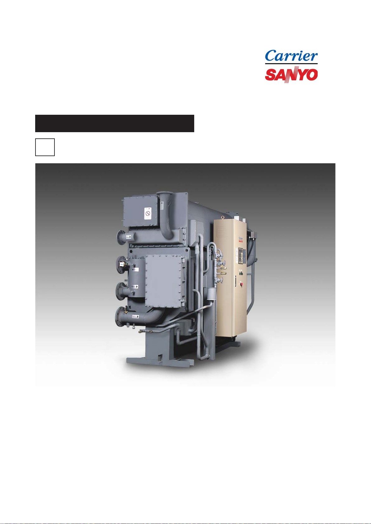
Absorption Chiller Installation Manual
<Hot water fired type>
Table of Contents
1. INSTALLATION
1-1. USE ENVIRONMENT ................................................................................................................... 1
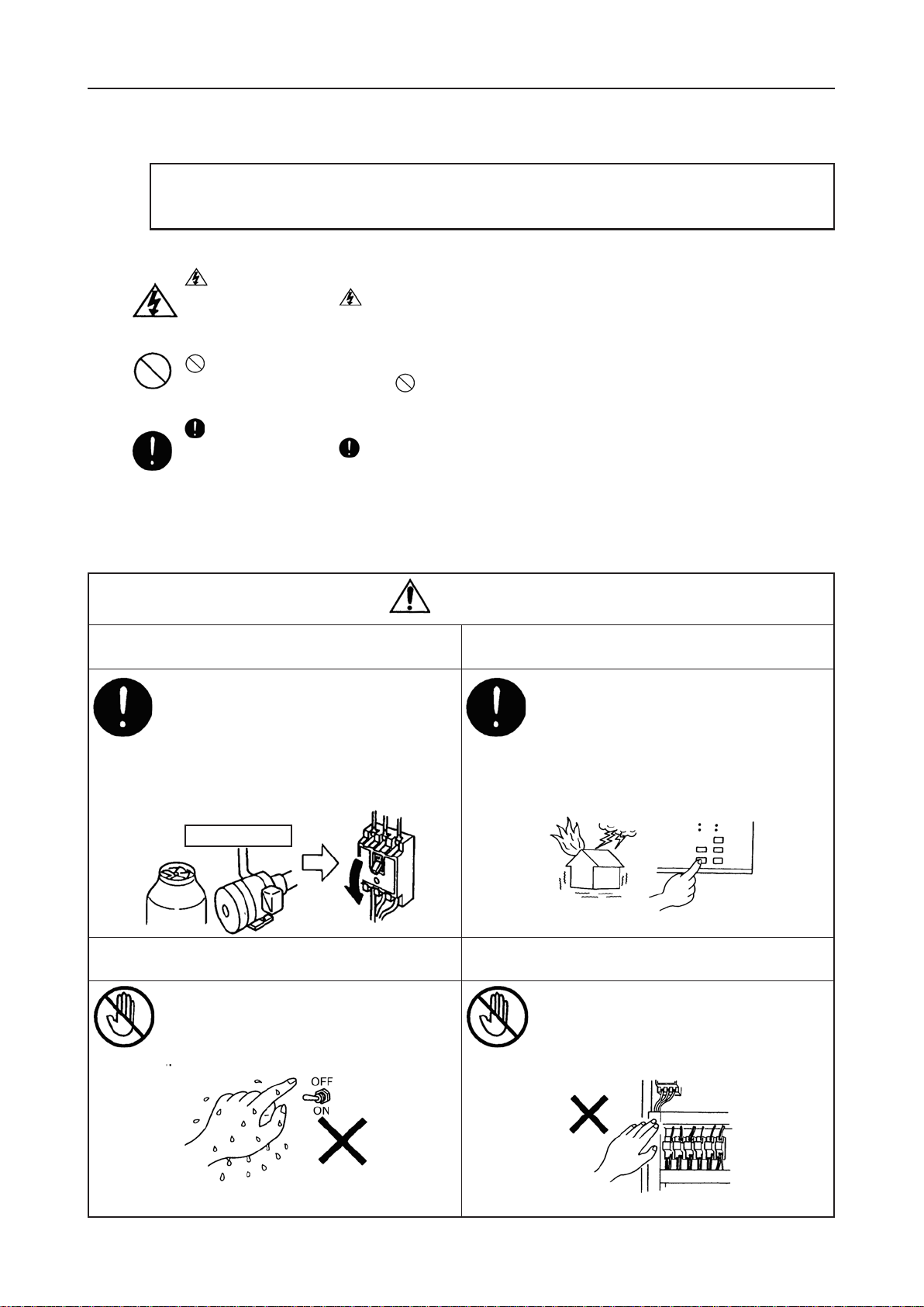
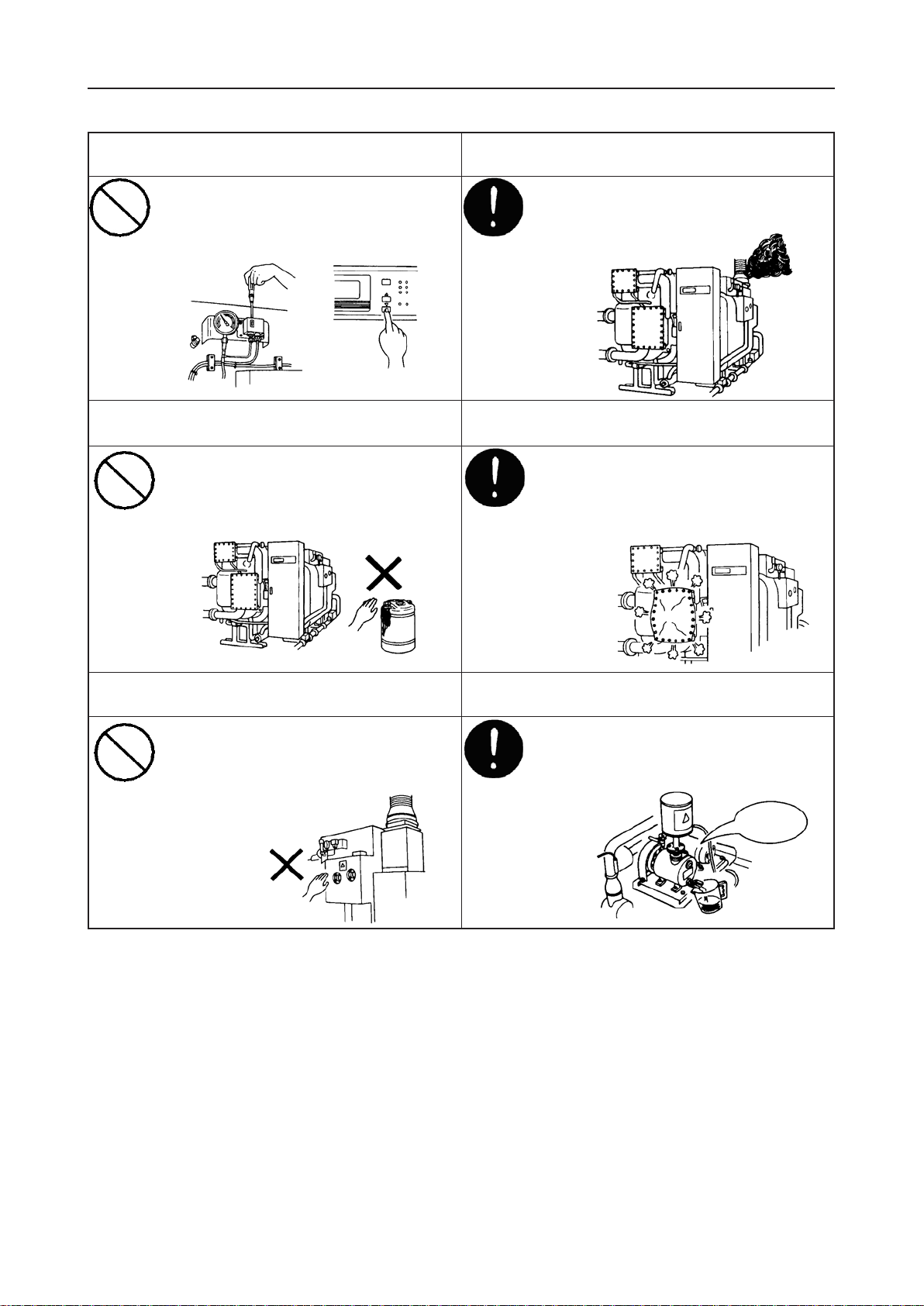
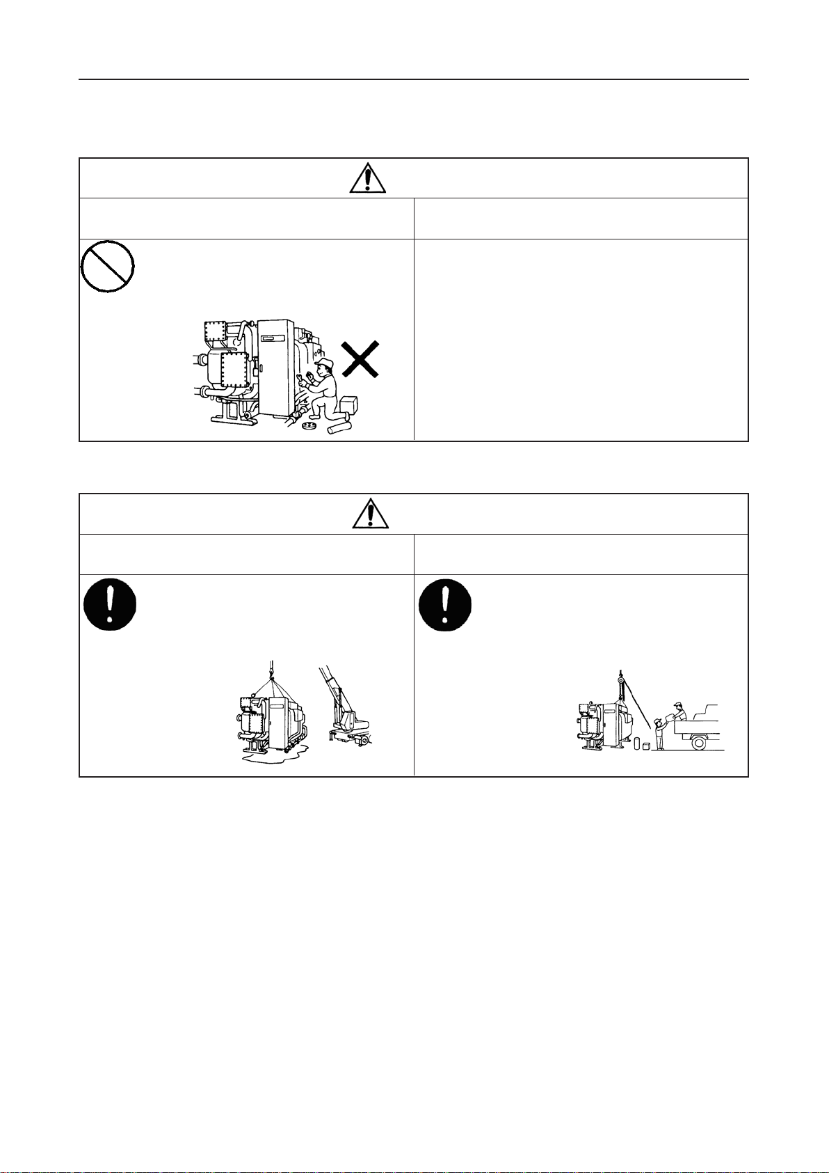
1-2. SAFETY INSTALLATION .............................................................................................................. 7
1-3. DELIVERY INSPECTION ............................................................................................................. 7
1-4. RIGGING ...................................................................................................................................... 9
1-5. SLIDING........................................................................................................................................ 9
1-6. SETTING ON THE FOUNDATION ............................................................................................... 9
1-7. LEVELING................................................................................................................................... 10
1-8. LEAK TEST, METHODOF CHARGING/DISCHARGING NITROGEN GAS ............................... 12
1-9. PIPING........................................................................................................................................ 18
1-10. FIELD WIRING ......................................................................................................................... 19
1-11. PURGING ................................................................................................................................. 20
1-12. INSULATION............................................................................................................................. 24
2. TEST OPERATION
2-1. EXTERNAL VISUAL INSPECTION............................................................................................. 25
2-2. ELECTRICAL CHECK ................................................................................................................ 26
2-3. INITIAL SETTING FOR OPERATION BOARD ........................................................................... 28
2-4. DAMPER SETTINGAND VALVE POSITION.............................................................................. 28
2-5. PURGING ................................................................................................................................... 28
2-6. FUNCTION TEST ....................................................................................................................... 29
2-7. OPERATION ............................................................................................................................... 32
CHECK LIST ........................................................................................................................................... 35
ExhibitLA........Precautions for use/Precautions for installation/FLOW DIAGRAM
ExhibitLB........Shipping dimensions
ExhibitLC........Foundation
ExhibitLE........Typical piping diagram/DIMENSIONS/RUPTURE DISK
ExhibitLF ........Field electric wiring/Wire size /ELEC WIRING DIAG/PARTS LIST
ExhibitLG .......Insulation
ExhibitLH........LiBr solution material safety data sheet
ExhibitLI .........Operation board operating instructions for confirmation of operation board parameters
ExhibitLJ ........DAMPER OPENING&VALVE POSTION

SAFETY PRECAUTIONS
1. INSTALLATION
1-1. USE ENVIRONMENT
1-1-1. Machine room
Absorption Chiller is indoor use ONLY.
IP number ofAbsorption Chiller is IP40.
Please keep the machine room temperature between 5°C and 40°C for protection of the solution
crystallization during chiller shut down. Please keep the humidity in the machine room within 90%.
1-1-2. Field wiring
For CE, please connect to power source by overvoltage category III, and to other wiring by
overvoltage category II.
1-1-3. Altitude
Please installAbsorption Chiller at a height of less than 1000m above sea level.
If the location is higher than 1000m above sea level, please contact Carrier/SANYO agent.
1

SAFETY PRECAUTIONS
1-1-4. SAFETY PRECAUTIONS
* Before operating this chiller, you should first thoroughly read the following instructions.
*All precautions are classified into either WARNING or CAUTION.
WARNING: Failure to observe this instruction may result in serious injury or death.
CAUTION : Failure to observe this instruction may cause an injury or failure of chiller/heater.
Depending on circumstances, this may result in serious injury or death.
< Example >
symbol denotes danger, warning or caution.
The illustration in the symbol shows the specific description of such item.
(The illustration to the left indicates that a special care must be taken to avoid electric shocks.)
symbol prohibits an action.
The illustration in or near the symbol shows the specific description of such item.
symbol instructs an action to be done.
The illustration in the symbol shows the specific description of such item.
(The illustration to the left indicates that it should be grounded.)
*After reading this manual, it should be kept in fixed place to be available for any user at any time.
TURN OFF THE BREAKER BEFORE CLEANING
AND CHECKING
Always turn off the breaker before cleaning
and checking the cooling tower fan,
chilled water pump, or others linking the
chiller, to provide protection from
electric shocks or possible injury by the
Must be observed rotating fan.
DO NOT TOUCH THE CONTROL PANEL
SWITCH WITH WET HANDS
Do not touch the switch inside the control
panel with wet hands to avoid electric
shocks.
Do not touch SWITCH
(1). For safety usage
WARNING
STOP THE OPERATION IN CASE OF AFIRE,
EARTHQUAKE OR POSSIBLE THUNDERBOLT
Stop the operation in case of a fire or
earthquake or when there is likely to be a
thunderbolt, to prevent a fire or electric
Must be observed shocks.
DO NOT TOUCH THE WIRINGS INSIDE THE
CONTROL PANEL
Do not touch the wirings inside the control
panel to avoid electric shocks.
Do not touch
INSPECTION
2

SAFETY PRECAUTIONS
DO NOT TOUCH HIGH VOLTAGE LEAD WIRE
Do not touch high voltage lead wire to
prevent electric shocks.
Do not touch
KEEP FLAMMABLES AWAY FROM THE
CHILLER
Do not place any flammables (gasoline,
thinner, etc.) close to the chiller,
flue, chimney and oil tank to prevent a fire.
Prohibited
DO NOT OPERATE THE CHILLER WHEN
GAS SMELLS
Do not operate the chiller when gas smells.
Do not turn on/off any switch to prevent a
fire.
Prohibited
DO NOT TOUCHANY ROTATING PART OF
FANS Keep away your fingers from any rotating
part of fans or pumps to avoid possible
injury.
Prohibited
3

SAFETY PRECAUTIONS
What
voltage?
CAUTION
DO NOT PLACE HEAVY OBJECTS ON THE
CHILLER• OR CONTROLPANEL
Do not place heavy objects on the
chiller or control panel to avoid
possible injury by falling.
Prohibited
CALL SPECIALISTS FOR SERVICE OR
MAINTENANCE
Call specialists for service or maintenance.
Wrong service /maintenance may cause
electric shocks, a fire or burns.
Must be observed
DO NOT POUR WATER OVER THE
CHILLER OR CONTROL PANEL
Do not pour water over the chiller or
control panel to avoid electric shocks.
Prohibited
USE THE CORRECT POWER SUPPLY
This is indicated on the name plate of the
chiller. Use of the power other
than specified here may cause a fire or
electric shocks.
Prohibited
SOLVE ALLTHE PROBLEMS BEFORE
RESTARTING THE CHILLER
Solve all the problems before restarting the
chiller/heater when the safety device or
security device operates, to prevent a fire.
Must be observed
DO NOT CLIMB UP THE CHILLER
Do not climb up the chiller to avoid
falling down.
Prohibited
AUTHORIZED PERSONNEL ONLY
A notice, “For Authorized Personnel Only”
must be affixed to the chiller to keep away
unauthorized personnel from
Prohibited touching it. If this is anticipated, enclose
the chiller with
a protective fence.
Misuse of the
chiller may
cause injury.
4

SAFETY PRECAUTIONS
STOP THE OPERATION WHEN BLACK SMOKE
RISES Stop the operation when black smoke
rises and call service agent, to prevent
a fire by poor combustion.
Must be observed
OBSERVE THE SPECIFIED PRESSURE OF
WATER The specified pressure of chilled/hot water
and cooling water must strictly beobserved.
Incorrect pressure may cause spout or
leak which may cause a short circuit or
burns.
Must be observed
STOP THE PURGE PUMP TO REPLACE OIL
Please stop the purge pump when
replacing oil to avoid possible injury by
fuel scatter.
Must be observed
NEVER CHANGE THE SET VALUE
Never change the set value of the safety
and/or protective devices. Wrong setting
may damage the chiller/heater or cause a
fire.
Prohibited
DO NOT TOUCH THE ABSORBENT
Do not touch the spare or leaked
absorbent which may cause corrosion of
metal areas or cause skin diseases.
Prohibited
DO NOT TOUCH THE HIGH TEMPERATURE
AREAS Do not touch the high temperature areas.
These areas are indicated by caution
label. Please avoid touching
such areas to prevent burns.
Prohibited STOP
5

SAFETY PRECAUTIONS
WARNING
ONLYAUTHORIZED PERSONNEL SHOULD
OVERHAUL THE CHILLER
Only those who are authorized should
overhaul the chiller.
Incomplete service could result in electric
shocks or a fire.
Prohibited
CAUTION
ONLYAUTHORIZED PERSONNEL SHOULD
DISPOSE OF THE CHILLER
To dispose of the chiller, contact the
local specialists.Any defecitive disposal
may cause corrosion of metal areas or skin
diseases by absorbent leak.
Must be observed
(2). Safety precautions for repair, moving or rejection
ONLYAUTHORIZED PERSONNEL SHOULD
REMOVE OR REPAIR THE CHILLER
Any relocation or moving of the
chiller should be done by authorized
personnel only. Incomplete work could
result in water leak, electric shocks or a fire.
Must be observed
6

1-2. SAFETY INSTALLATION
Aproper skilled installer should carry out the equipment installation.
Take safety measures during installation works.
Take measures to prevent unauthorized people from entering installation site
during installation work.
1-3. DELIVERY INSPECTION
Upon delivery of the Carrier/Sanyo Chiller to the job site, the owner or his designated
representative should carefully inspect the Chiller for the following items:
1-3-1. The Chiller is filled with nitrogen gas of 20kPa, when it is shipped from factory.
Open SV7. Connect the vacuum gauge to SV2. Open SV2 and SV3 Check the pressure of
the vacuum gauge. If the pressure becomes to 0kPa, the Chiller has leak. In this case,
please check the leak point by pressurized nitrogen gas at 50kPa. Close the cap of SV7 with
sealant. Refer to Exibit LA and 1-8-1.
1-3-2. Check for physical damage to the Chiller
(1) Main shell
(2) Valves
(3) Control panel
(4) Wiring and connection
(5)Accessory
(6) Solution
1-3-3. Check the shipping or packing slip sent with the Chiller and note any missing items.
1-3-4. Check any separate boxes or crates shipping with the Chiller for any missing items.
NOTE 1. Isolation pads are not required for most installations.
NOTE 2. Inform Carrier/Sanyo within 24 hours of any damage or missing items.
7

SOLUTION VOLUME
Model Name Absorbent Refrigerant Alcohol Inhibitor
kg lbs kg lbs cc gal cc gal
LJ-11E 430 900 60 130 780 0.21 250 0.07
LJ-12E 430 900 60 130 780 0.21 250 0.07
LJ-13E 560 1,200 100 220 1,020 0.27 330 0.09
LJ-14E 620 1,400 90 200 1,120 0.30 360 0.10
LJ-21E 750 1,700 110 240 1,360 0.36 440 0.12
LJ-22E 810 1,800 120 260 1,480 0.40 480 0.13
LJ-23E 980 2,200 150 330 1,780 0.48 570 0.16
LJ-24E 1,070 2,400 140 310 1,940 0.52 620 0.17
LJ-31E 1,230 2,700 190 420 2,240 0.60 720 0.20
LJ-32E 1,340 3,000 170 370 2,440 0.65 780 0.21
LJ-41E 1,560 3,400 250 550 2,840 0.76 910 0.25
LJ-42E 1,680 3,700 230 510 3,060 0.81 980 0.26
LJ-51E 1,950 4,300 260 570 3,540 0.94 1,130 0.30
LJ-52E 2,170 4,800 290 640 3,940 1.05 1,260 0.34
LJ-53E 2,420 5,300 310 680 4,400 1.17 1,400 0.37
NOTE Absorbent: LiBr 50wt%
Inhibitor : Li2MoO420wt%
300ppm (Total Concentration)
Alcohol : Octyle Alcohol CH3(CH2)5CH(OH)CH3
8

1-4. RIGGING
In case that a chiller is lifted up, check first weight of the chiller by referring its contract
specifications and then choose and use suitable lifting wires and shackles. Since 4 holes are
provided on the conners of lower tube sheet, use the holes to lift the chiller. Note that the
angle of wires shall be within 60 deg. as shown in the figure below. Please refer to Exhibit LB.
1-5. SLIDING
In case that sliding of the chiller is required, using tiltdozers (trail-builders) is recommended.
If a wire to slide the chiller is used, the wire shall be connected as shown in the figure below.
1-6. SETTING ON THE FOUNDATION
Please refer the foundation to Exhibit LC.
Please set the Chiller on the foundation bolt position.
9

1-7. LEVELING
1-7-1. Fill a clear vinyl hose with water, checking that there are no air bubbles in the hose.
1-7-2. Using point A as the reference point, measure the difference in the water level at the other
points (B, C and D).
AB
(Evaporator side)
(Absorber side)
CD
ABCD
0 mm mm mm mm
1-7-3. Leveling calculation as shown.
A-B C-D A-D B-C A-C B-D
L L L L WW
Tolerance < L : Chiller length
W : Chiller width
1-7-4. Note that there are four leveling check points on the chiller labeledA, B, C and D
in the sketch below. These check points are designated by three punch markers
on the tube sheet or shell of the lower shell.
2
1000
10

1-7-5. If tolerance are not met, shim the appropriation points by inserting a metal shim between
the frame and foundation.
Metal shim size is approximately 50mm width and 80mm length. Prepare the shim of some
different thickness (0.6mm to 9mm).
1-7-6. Fix the anchor bolts
a) Weld the washers on the chiller's frame.
b) Tight up the nuts.
11

1-8. LEAK TEST, METHOD OF CHARGING/DISCHARGING NITROGEN GAS
If the chiller has some leaks, please work this items.
1-8-1. Instruction for leak test
This instruction describes the procedure of leak test for the Chiller
by means of pressurizing with nitrogen gas (hereinafter called N2gas).
(1) Equipment use
a) Nitrogen gas cylinder
b) Pressure regulator
c) Pressure proof hose
d) Flashlight
e) Soapy water
f) Adjustable wrench
g) Hose band
h) Vacuum gauge (0-100kPa)
(2) Standard
Pressurize the Chiller up to 50 kPa with the nitrogen gas, then confirm that any bubble
shall not be observed by the soapy water and any oozy liquid shall not be visually observed.
(3) Sequence of this test
----
Refer to 1-8-2
Check leakages.
OK NG
(Note) The repair welding can be done after discharging N2gas.
Refer to 1-8-3.
Discharge N2gas
Air purging
Charge N2gas
Perform recheck.
Check at 50kPa
Perform tightening up.
Discharge N2gas and repair. Charge N2gas up to
12

(4) Procedure
a) Confirm that V1, V2, V3, B valve, SV1, SV2 are fully closed.
b) Confirm that each isolation valve for absorbent and refrigerant pumps are fully opened.
c) Connect the vacuum gauge to SV2. and open SV2.
d) Charge N2gas (Refer to 1-8-2).
e) Pressurize the Chiller up to 50 kPa with N2 gas. The pressure inside the Chiller can be checked by
the vacuum gauge.
f) When the pressure reaches 50 kPa, close the service valve and the valve of the N2gas cylinder.
g) Check the following positions with the soapy water.
g-1) All field welded portions (One shipping machine is not needed.)
g-2) Sight glass
g-3) Flare nut joints of service valves.
g-4) Flange connections ( the absorbent pumps, refrigerant pump, etc.)
g-5) Diaphragm valves
13

h) If any leakages are observed at above g-2) - g-5), tighten them without discharge of the N2gas.
i) If there are any leakages at the welded portions, discharge the N2gas and then repair them.
j) Repeat c) - g).
k) If no-leakage is confirmed at 50kPa of the pressure, keep the Chiller under the pressurizing condition
with 50kPa for 24 hours, and then check the pressure again.
l) After completion of the test, discharge the N2gas, and remove the vacuum gauge.
( Refer to 1-8-3.)
m)Close SV2.
Note
In case of discharging the N2gas, perform ventilation sufficiently.
14

1-8-2. Method of charging nitrogen gas
This instruction describes the procedure to charge nitrogen gas (hereinafter called N2gas) to the
Chiller.
(1) Equipment use
a) N2gas : Required volume
Content volume
b) Pressure regulator
c) Pressure proof hose
d) Adjustable wrench
e) Valve key for N2gas cylinder
f) Vacuum gauge (0-100kPa)
(2) Standard
The pressure in the Chiller is charged until 50kPa at generator pressure gauge.
(3) Precautions
a) Since the N2gas cylinders are pressurized up to 15MPa, pay attention to handle them.
b) Do not suddenly raise the primary or secondary pressure of the pressure regulator.
c) Fix the N2gas cylinder so that it does not fall over.
d) Be sure not to open V1, V2 during this work.
Model Volume Model Volume
LJ- (litter) LJ- (litter)
11E 1,640 31E 5,030
12E 1,580 32E 4,830
13E 2,510 41E 6,150
14E 2,380 42E 5,910
21E 3,150 51E 8,240
22E 3,010 52E 9,350
23E 4,210 53E 10,350
24E 4,020
15

(4) Procedure
a) Prepare N2gas cylinders and attach a pressure regulator to a N2gas cylinder.
b) Connect the vacuum gauge to SV2. Open SV2.
c) Connect a pressure proof hose to the outlet of the pressure regulator, then slightly open
a valve on the top of the cylinder in order to purge air being in the hose.After purging,
close the valve.
d) Connect the other end of the hose to SV1 and fix it with a hose band.
e) Check that V1, V2, V3, B, SV1, are fully closed.
f) Open the V3, B valve and then open SV1.
Note: B valve shall be closed after solution charge in the Chiller.
g) Using the pressure regulator, charge a small amount of N2gas into the Chiller.
h) Watch the vacuum gauge during charging of N2gas. When the pressure inside the Chiller
reaches to required pressure, close SV1, V3, and B valve, and then close the valve of the
cylinder.
i) Remove the hose from SV1 and place a cap of the service valve to the service valve.
j) Remove the pressure regulator, and vacuum gauge.
k) Close SV2.
16

1-8-3. Method of discharging nitrogen gas
This instruction describes the procedure to discharge N2gas form the Chiller.
(1) Equipment use
a) Adjustable wrench
(2) Standard
The pressure in the Chiller is discharged until atmospheric pressure.
(3) Precautions
1) Be sure not to open V1, V2 during this work.
2) During this work, adequately ventilate a machine room.
(4) Procedure
a) Check that the V1, V2, V3, SV1, SV2 are fully closed.
b) Open V3.
c) Remove a cap and a flare nut of SV1, and open it.
d) When the reading of the generator pressure gauge becomes atmospheric pressure,
close SV1and V3.
17
This manual suits for next models
15
Table of contents
Other Carrier-Sanyo Chiller manuals