2
FAN COIL CONTROLLER — To read the current fan
speed:
To enter fan speed selection, press the FAN button. The
present fan position will be read in from the attached device. If
the fan is Off, then the “Fan” icon with no curved lines will be
displayed. If the fan is On, then the graphic will show one set
of curved lines around the fan to represent Low Speed, two
lines for Medium Speed, and three lines for High Speed. See
Fig. 2.
To change Fan mode when User Control mode is enabled:
1. Press the INC or DEC buttons to cycle through the vari-
ous Fan modes until reaching the desired fan setting. The
modes will be displayed in the following wraparound
order — Off, Low, Medium, High, and Auto. Auto mode
will be indicated by a blinking “fan” icon with no curved
lines. Auto mode can be set by the T58 sensor, but when
reading the Fan mode, only the current fan speed or Off
will be displayed.
2. Press the FAN button again to terminate the operation and
send the new Fan mode value to the attached device. The
selected “fan” icon will also disappear from view denot-
ing the end of the operation.
NOTE: Some fans may only be single-speed (Off/On) or
two-speed (Low/High). In either of those cases, if the de-
sired fan selection is higher than the top selection, the fan
will be driven to its highest setting. As an example, if a
one-speed fan is commanded to go to Medium or High
Speed, then that command will be interpreted to turn on
the fan. If a two-speed fan is commanded to go to Medi-
um or High Speed, then that command will be interpreted
to drive the fan to its highest possible speed setting.
AIR TERMINAL CONTROLLER AND ROOFTOP
CONTROLLER — To read the current fan speed:
To enter fan speed selection, press the FAN button. The present
Fan mode is read in from the attached device. If the fan is OFF,
then the “fan” icon without curved lines will be displayed. If
the fan is On the fan graphic and the first set of bars will be
displayed.
To change Fan mode when User Control mode is enabled:
1. Press the INC or DEC button to cycle between Fan On,
Fan Off, or Auto. A blinking “fan” icon indicates Auto
mode (Fan only — no curved lines).
2. Press the FAN button again to complete the operation and
send the new Fan mode to the attached device. If Auto
mode is selected, an auto command for the fan will be
sent to the attached device. The selected FAN icon
will also disappear from view denoting the end of the
operation.
NOTE: If no button is pushed for 10 seconds after initiat-
ing FAN mode, the “fan” icon will disappear and no
change will be enacted on the fan speed.
NOTE: If there is no attached device then an error code of
“E2” will be displayed in the numeric portion of the LCD
area.
Read/Modify Current Set Point Value —
The INC and DEC buttons are used to read or modify the con-
figured occupied set points of the attached device. This feature
is the same for all controllers.
TO READ CURRENT SET POINTVALUE — Press the INC
or DEC button once. This will display the set point that will be
adjusted. Pressing INC will make the space warmer and press-
ing DEC will make it cooler. See Table 4.
TO MODIFY CURRENT SET POINT VALUE (If User
Control Mode is Enabled) — Once INC or DEC is pressed
the “temperature bulb” icon will appear. This indicates the
onset of “Modify Set Point” mode. The Inc or Dec button can
be used to adjust the displayed set point. The heat set point will
have an allowable range of 40 F to the heat set point Hi Limit
configured in installer option 9. The cool set point range goes
from the cool set point to the limit configured in installer
option (range 10 to 99 F). If the read set point exceeds the con-
figured limit, it will be used as the limit. Wraparound is not
enabled for this function. A difference of at least 2 F will be
maintained between the occupied heating and cooling set
points. If one set point is adjusted to within less than 2 F of the
other, the other set point will also be adjusted to maintain the
2 F separation. The appropriate icon for heat (“sunshine” icon)
or cool (“snowflake” icon) will blink while adjusting the set
point.
• When the desired set point is reached, press the MODE
button to cause the new set point value to be saved in the
attached device. At the same time, the LCD display will
return to the default Space Temperature display, and the
“set point” icon will disappear.
• If the attached device is unoccupied, the T58 will also
send a command to initiate a Time Schedule Override in
the attached device. This will allow the modified (occu-
pied) set point(s) to take effect immediately. The “over-
ride” icon (clock) will be displayed while the override is
in effect.
• While in Modify Set Point mode, after ten seconds of
being idle the LCD will return to the default Space Tem-
perature display and the “set point” icon (thermometer)
will disappear. The last displayed set point will be sent to
the attached device.
NOTE: If there is not a device attached or if the attached
device is not a supported CCN type, an error code of “E2” will
be displayed in the numeric portion of the LCD area. See
Table 5.
NOTE: Refer to Tables 1-3 for ICON definitions.
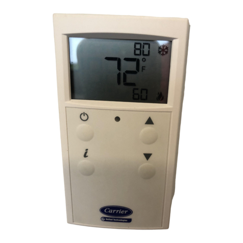
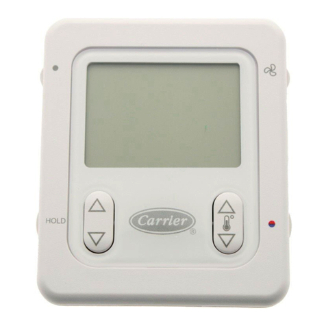
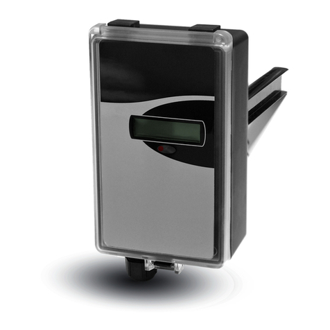
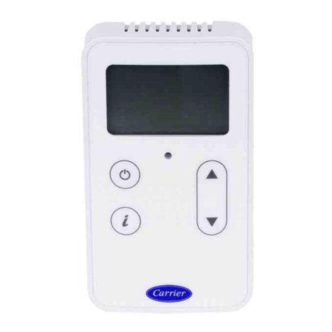
Fig. 2 — T58 Sensor Display Icons
