Carrier 09PE Manual

Translation of the original document
INSTALLATION, OPERATION AND
MAINTENANCE INSTRUCTIONS
Drycooler and air-cooled condenser
09PE

CONTENTS
1 - RECEIVING THE UNIT.................................................................................................................................................................... 4
1.1 - General checks ........................................................................................................................................................................... 4
1.2 - Unloading .................................................................................................................................................................................... 4
2 - SAFETY INSTRUCTIONS ............................................................................................................................................................... 4
2.1 - In an emergency.......................................................................................................................................................................... 4
2.2 - The 4 main risks.......................................................................................................................................................................... 4
3 - GENERAL INFORMATION.............................................................................................................................................................. 4
3.1 - Unit functions............................................................................................................................................................................... 4
3.2 - Standards.................................................................................................................................................................................... 4
3.3 - Warranty...................................................................................................................................................................................... 4
4 - NAME PLATE .................................................................................................................................................................................. 5
4.1 - Description .................................................................................................................................................................................. 5
5 - INSTRUCTIONS FOR LIFTING AND PLACING THE FEET IN THE OPERATING POSITION AND FOR SHIPPING.................. 6
5.1 - Lifting HORIZONTAL units .......................................................................................................................................................... 6
5.2 - Lifting VERTICAL units................................................................................................................................................................ 6
5.3 - Lifting CLUSTER units ................................................................................................................................................................ 7
5.4 - Instructions for placing the feet in the operating position ............................................................................................................ 7
5.5 - Shipping ...................................................................................................................................................................................... 8
6 - STORAGE........................................................................................................................................................................................ 8
7 - INSTALLATION ............................................................................................................................................................................... 8
7.1 - Maximum permitted wind speed.................................................................................................................................................. 8
7.2 - Air intake height........................................................................................................................................................................... 9
8 - INSTALLATION RECOMMENDATIONS ....................................................................................................................................... 10
9 - CONNECTIONS............................................................................................................................................................................. 10
9.1 - Electrical connection ................................................................................................................................................................. 10
9.2 - Fluid connection ........................................................................................................................................................................ 10
9.3 - Connecting a speed regulator ................................................................................................................................................... 10
10 - OPERATION ................................................................................................................................................................................ 11
10.1 - First commissioning..................................................................................................................................................................11
10.2 - In the event of faults ................................................................................................................................................................11
10.3 - Recommendations for use .......................................................................................................................................................11
11 - AC FAN MOTOR ASSEMBLIES.................................................................................................................................................. 11
11.1 - AC motor protection..................................................................................................................................................................11
11.2 - Fan with AC motor (3-ph 230 V/400 V 50 Hz) ..........................................................................................................................11
11.3 - Fan with AC motor 3-ph 208 V and 3-ph/400 V to 480 V 60 Hz...............................................................................................11
12 - EC FAN MOTOR ASSEMBLIES.................................................................................................................................................. 12
12.1 - EC motor protection ................................................................................................................................................................ 12
12.2 - Fan with EC motor (3-ph 380 V to 480 V 50/60 Hz)................................................................................................................ 12
The illustrations in this document are for illustrative purposes only and not part of any offer for sale or contract. The manufacturer reserves the right to change the design
at any time without notice.
2

TRANSLATION OF THE ORIGINAL TEXT: ENGLISH VERSION
CONTENTS
13 - ATEX (STANDARD) FAN MOTOR ASSEMBLIES ...................................................................................................................... 12
14 - MAINTENANCE........................................................................................................................................................................... 13
14.1 - Recommendations for maintenance........................................................................................................................................ 13
14.2 - Maintenance frequency........................................................................................................................................................... 13
14.3 - Information relating to condensers.......................................................................................................................................... 13
14.4 - Cleaning the coils.................................................................................................................................................................... 14
14.5 - Removing and retting a fan ................................................................................................................................................... 14
15 - MAINTENANCE SWITCHES OPTION........................................................................................................................................ 16
16 - PROTECTION CABINET OPTION.............................................................................................................................................. 16
17 - CONTROL CABINET WITH ELECTRONIC BOARD OPTION................................................................................................... 17
18 - ELECTRICS BOX OPTION ......................................................................................................................................................... 18
19 - STAGING FOR CONTROL CABINET OPTION .......................................................................................................................... 19
20 - OPTION FOR CONTROL CABINET CONTROLLED BY THE CHILLER (AUX1) ..................................................................... 20
21 - STAGING FOR THE CONTROL CABINET CONTROLLED BY THE CHILLER OPTION (AUX1). ........................................... 21
22 - EXPANSION VESSEL OPTION .................................................................................................................................................. 22
23 - SPECIAL INFORMATION FOR ATEX AREAS ........................................................................................................................... 23
23.1 - General information................................................................................................................................................................. 23
23.2 - Periodic inspections/checks .................................................................................................................................................... 24
23.3 - Using tools in an explosive atmosphere.................................................................................................................................. 25
23.4 - Appendix.................................................................................................................................................................................. 25
24 - DESTRUCTION OF THE UNIT.................................................................................................................................................... 26
3

1 - RECEIVING THE UNIT
1.1 - General checks
■ Each unit has a data plate bearing an identication number.
This number must be included in all correspondence. Ensure
that it is the correct unit by checking the purchase order.
■After unpacking the unit, please inspect it for any damage.
■If any items are missing or in case of damage, specify this on
the delivery slip and inform the carrier by registered letter within
3 days of delivery of the unit.
1.2 - Unloading
■The recipient shall be responsible for unloading the equipment and providing the necessary handling equipment (see the section
entitled "LIFTING INSTRUCTIONS").
2 - SAFETY INSTRUCTIONS
■ Any operation must be carried out by qualied personnel using the appropriate Personal Protective Equipment (PPE).
■Before any operation, read this guide carefully and keep it in a safe place. Safety information must be adhered to.
■The units must not be run under operating conditions which are more restrictive than those it was designed for (pressure,
temperature, type and circulation of uids).
■For units installed in European Community countries, ensure that the entire installation complies with the directives and legislation in force.
■Respect the instructions for using slings (see the labels on the unit).
■To prevent any risk of accident, prohibit public access by clearly marking the work area.
2.1 - In an emergency
■Switch off the electrical supply.
■The process should not be jeopardised if the emergency stop devices are activated.
■Switch off the fans.
2.2 - The 4 main risks
■Lifting or positioning = Accident
■Contact with the piping = Burns
■Opening the electrics box = Electrocution
■Removing the grilles = Injury
3 - GENERAL INFORMATION
3.1 - Unit functions
■Drycooler: Device in which a uid in liquid state is cooled by heat exchange with the ambient air, without direct contact between
the ambient air and the uid.
■Condenser (or air-cooled condenser): Device in which a gas is condensed by heat exchange with the ambient air.
■Misting option: System for cooling air by misting of water droplets under high pressure.
■ These devices must only be used for the purpose for which they are intended. In particular, it is formally prohibited to use any uid
other than that specied in the order documents.
3.2 - Standards
■Every unit meets standards EN 60-204 and EN 14 276-1 as well as the following European directives:
-Machinery 2006/42 EC
-EMC 2014/30/EU
-PED 2014/68/EU
■Technicians who install, commission, operate and service the unit must understand the instructions given in this manual and be
familiar with the specic technical characteristics of the installation site.
3.3 - Warranty
■See general terms and conditions of sale.
■Check the compatibility of the fluid with the equipment being used.
■To find out the limits of use, refer to the name plate.
4

4 - NAME PLATE
■Désignation\Description: See "Description".
■An (Year): Year of manufacture.
■N° série/Serial Nbr: number to be quoted in all
correspondence.
■DIR 2014/68/EU (DN): Category and determining value
(DN for "PIPES", Capacity for "CONTAINERS").
■Fluid CIRC. 1: type of uid in circuit 1.
■Fluid CIRC. 2: identical to Fluid CIRC 1, only for units
with 2 circuits.
■Voltage: Power supply.
■Volume: Capacity of the circuit.
■P.Abs/P.Input: Power input.
■P.serv.\ Working P (PS) : Working pressure. (Maximum allowable pressure set out in European Directive 2014/68/EU).
■Current (+/-10%): Maximum current.
■Max. temperature: Maximum permitted temperature.
■Poids/Weight: Maximum empty weight including options and accessories.
4.1 - Description
E.g.: DLN 8083-2 SHI A 690A8B 12A1
D: Function: D = Drycooler, C = Condenser
L : Module size: S = short,
M = medium,
L = long
N or X: Type of design: N = standard, X = special
8: Impeller diameter (dm): 8 or 9
08: Number of fans: 01 to 14
3: Number of rows of nned tubes: 2, 3, 4 or 5
2: Number of fan lines: 1 or 2
S: Coil specication: S = single coil,
D = double coil,
T = 2 refrig. circuits
Z = drainable coil
H: Unit position: H = horizontal, V = vertical
I: Draught: I = induced,
F = forced
690: Rotation speed (rpm)
A8B: Motor type: A9A/A9B/A9C/A9D = Ø 910 mm AC motors (3-ph/400 V/50 Hz),
A8A/A8B/A8C = Ø 800 mm AC motors (3-ph/400 V/50 Hz),
B9A/B9B/B9C = Ø 910 mm AC motors (other voltages),
B8A/B8B/B8C/B8D = Ø 800 mm AC motors (other voltages),
E9A/E9B = EC motors Ø 910 mm,
E8A/E8B/E8C = Ø 800 mm EC motors,
X9A/X8A = ATEX motors,
M8 = 1 stage with Ø 800 mm EC motor fans
M9 = 1 stage with EC motor fans Ø 910 mm
12A1: Fin type: 09A1 = Tube Ø 9.52 mm
12A1 = Tube Ø 12.7 mm
16B2 = Tube Ø 16/15.87 mm
Designation/Description
Ref. produit\Item Ref.
An(Year) N. Serie/Serial Nbr PED 2014/68/UE (DN)
Fluid CIRC. 1 Fluid CIRC. 2 Voltage
P. abs \ P. inputVolume
P.serv.\ Working P (PS) Courant (+/-10%)
Poids-WeightMax. Temperature
2011 00089442/003
7278227.159 DMN 8083-2 SHI 690A 12A1
EAUTRI 400 50HZ
13800 W438L
1.00 (10.0) BARS
110 °C
27 A
ART4.3-LIQ-GR2 (DN: 150)
2270 KG
5

5 - INSTRUCTIONS FOR LIFTING AND PLACING THE FEET IN THE OPERATING
POSITION AND FOR SHIPPING
■The weights are given on the data plates.
■Attach the slings to the sling points indicated by the yellow labels.
■We recommend fitting protection between the casing and the hooks to prevent damage to the paintwork.
■Never lift horizontal units by the feet.
5.1 - Lifting HORIZONTAL units
■The horizontal units marked in the table below with a (!) symbol must be lifted using a spreader beam.
Lifting using a spreader beam
Lifting using a crane
A A A
B
B B
A = B
< 60°
> 60°
E
E
E
E
E
E
1067 1067 1067
HH
H
1023
5.2 - Lifting VERTICAL units
Lifting using a spreader beam Lifting using a crane
E
E
E
1067 1067 1067
H
H
H
1023
FMA
line number
FMA
number A = B HE
S module (950 mm) M module (1600 mm) L module (1900 mm)
1
1
1180 1375
950 (!) 1600 (!) 1900
2 1900 3200 3800 (!)
3 2850 4800 (!) 5700 (!)
4 3800 (!) 3200 3800 (!)
5 2850 4800 (!) 5700 (!)
6 1900 - -
2
4
2300 2495
1900 (!) 3200 (!) 3800
6 2850 (!) 4800 5700
8 3800 3200 (!) 3800
10 2850 (!) 4800 5700
12 1900 (!) 3200 (!) 3800
14 2850 (!) 4800 -
6

5.3 - Lifting CLUSTER units
NEVER LIFT BOTH UNITS TOGETHER
Separate the two units by removing the bolts connecting the feet
Remove the upper unit
Remove the second unit
(The plastic shims and bolts will be recycled)
5.4 - Instructions for placing the feet in the operating position
■The feet are in the "transport" position (A) when the unit is delivered.
■ When the unit is nally installed, the feet must be moved to the "use" position (B).
To do this:
Lift the upper unit using the lifting rings. Keep the unit raised throughout the procedure.
Unscrew the 4 mounting bolts on each foot. The other bolts must never be unscrewed. Pull out the foot to reposition it
one notch lower, in its nal position.
Retighten the 4 bolts on each foot, then reposition the unit on the ground.
AB
2
1
3
For the "Skid container" and/or raised feet option, see the additional instructions enclosed with the unit.
2
1
5 - INSTRUCTIONS FOR LIFTING AND PLACING THE FEET IN THE OPERATING
POSITION AND FOR SHIPPING
7

5.5 - Shipping
■Follow the handling instructions affixed to the packages
■Do not stand on the packages
■Do not place anything on top of the packages
■Strap the packages onto the deck of the truck
■Only textile straps are authorised (lifting and coupling)
■Use an open top for container shipping single-line machines, but use the option intended for this purpose for other machines.
6 - STORAGE
■Store the units at a temperature of between -40 and +60°C (temperature range for standard units). For options, see the relevant
description.
■Protect the units against impacts and ensure that they only support their own weight.
■Place the units on firm, flat and level ground. For storage in very windy areas, affix the unit to the ground using straps or cables.
■Leave the blanking trim for the pipes in place before connecting the unit.
■For long-term storage (over 3 months), fill the exchanger with an inert gas and seal the pipes using caps. This is necessary to
prevent the formation of condensation and oxidation. Warning: do not exceed the maximum operating pressure indicated on the
data plate.
■For long-term storage, it is recommended to place the units in an area protected from adverse weather conditions.
7 - INSTALLATION
■Contact us for projects with a "special" seismic risk.
■Before setting up the unit in its intended location, the installer must check the following points:
-The unit must be installed outdoors in an area protected from flooding. Ensure that all conditions have been taken into account
(negative outdoor temperatures, corrosive atmosphere, altitude, etc.)
-The ground surface or structure must be level and strong enough to bear the unit's weight.
-Raise the unit if it is installed in a snowy area, in order to ensure a sufficient air intake height.
-At the design stage, check that the installation location is compatible with the unit's sound level.
-For vertical units, the flow of air crossing the unit must not be parallel to the prevailing wind.
-Protect the unit from sandstorms using the appropriate infrastructure.
-Waste from vegetation is a major factor contributing to the clogging of the coil; avoid installing the unit close to deciduous trees.
-Do not install the unit near hot air extraction duct outlets.
7.1 - Maximum permitted wind speed
■Maximum permitted speed: 100 Km/h.
■For speeds > 100 Km/h, contact us.
5 - INSTRUCTIONS FOR LIFTING AND PLACING THE FEET IN THE OPERATING
POSITION AND FOR SHIPPING
8

7.2 - Air intake height
■The installer must take all necessary precautions to limit the recycling of hot air and ensure a good air supply to the unit.
■Determining the NPSH (H) for the following cases:
S = Floor surface area
P = Air intake perimeter
-Several units are placed side by side to prevent the risk of air recycling (air intake on 4 sides)
-only 1 unit placed against a wall (air intake on 3 sides)
-only 1 unit placed against 2 walls (air intake on 2 sides)
-only 1 unit placed against 3 walls (air intake on only 1 side)
■For other scenarios, please contact us.
H > 0.8 —
S
PH
A
B
A
B
S = A x B
P = 2 (A
+ B)
S = A x B
P = A + 2B
S = A x B
P = A + B
S = A x B
P = A
A
B
A
B
7 - INSTALLATION
9

8 - INSTALLATION RECOMMENDATIONS
■Ensure sufficient devices are provided to guarantee the protection of persons and property, and to enable maintenance operations
to be carried out in complete safety.
■If a malfunction would have significant human, environmental or financial consequences, take appropriate steps to limit the effects.
■Ensure that the installation complies with the legal texts and codes in force in the country of operation, and that it complies with the
safety rules applicable to the site where it is being used (explosive atmosphere, for example).
■If necessary, affix to the machine the hazard symbol corresponding to the fluid in accordance with current standards.
■Install burn hazard signs wherever the internal temperature of pipes exceeds 65°C.
■Fit safety devices to prevent the fluid temperature or pressure from exceeding the values indicated in the order. Approval for operation
at higher conditions must be obtained from us.
■The unit must be fitted with an immediately accessible emergency stop device; this visible device must allow the electrical supply
to the unit and its accessories to be cut completely.
■Ensure that cutting off the electrical supply, whether intentionally or accidentally, does not jeopardise the process.
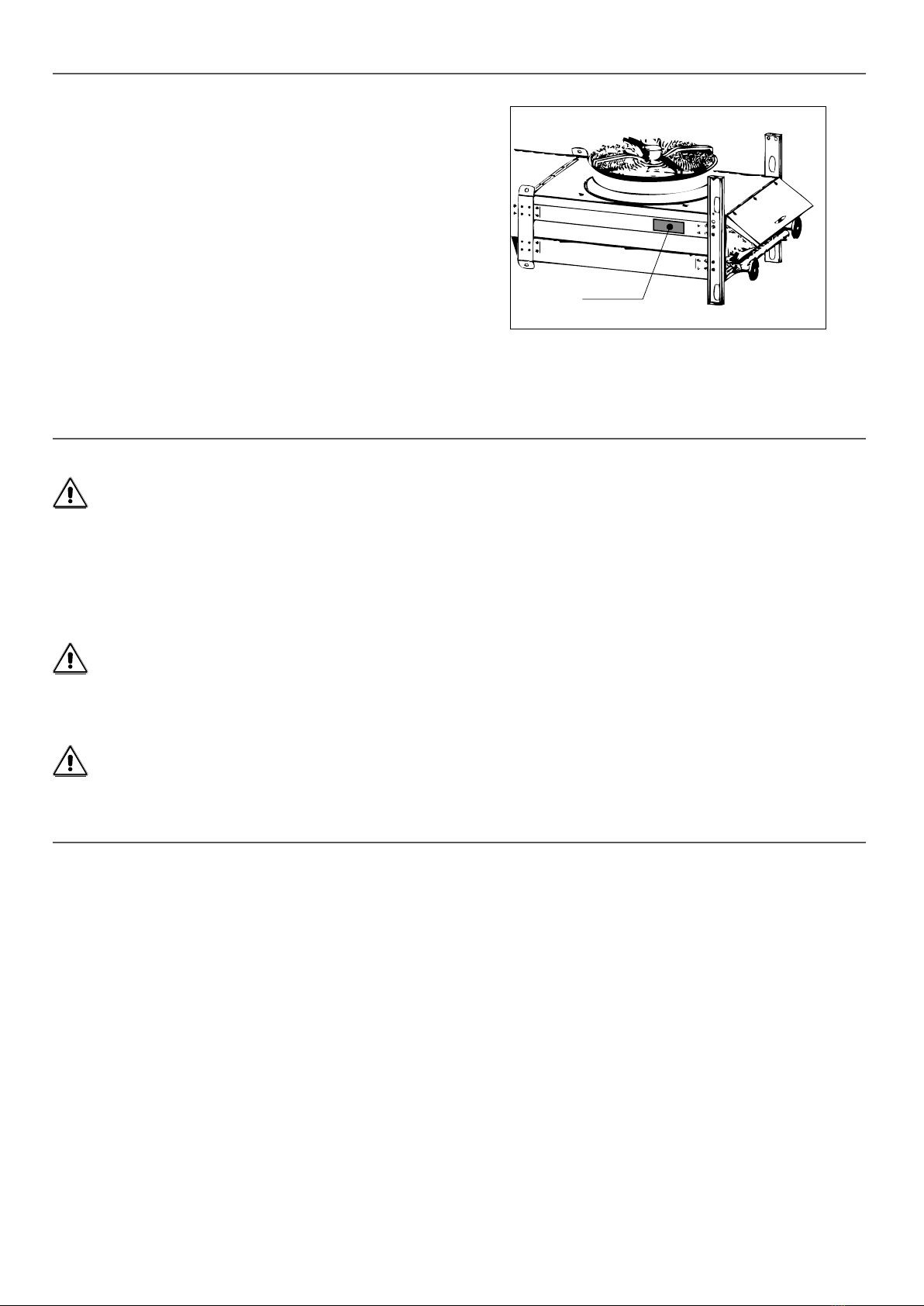
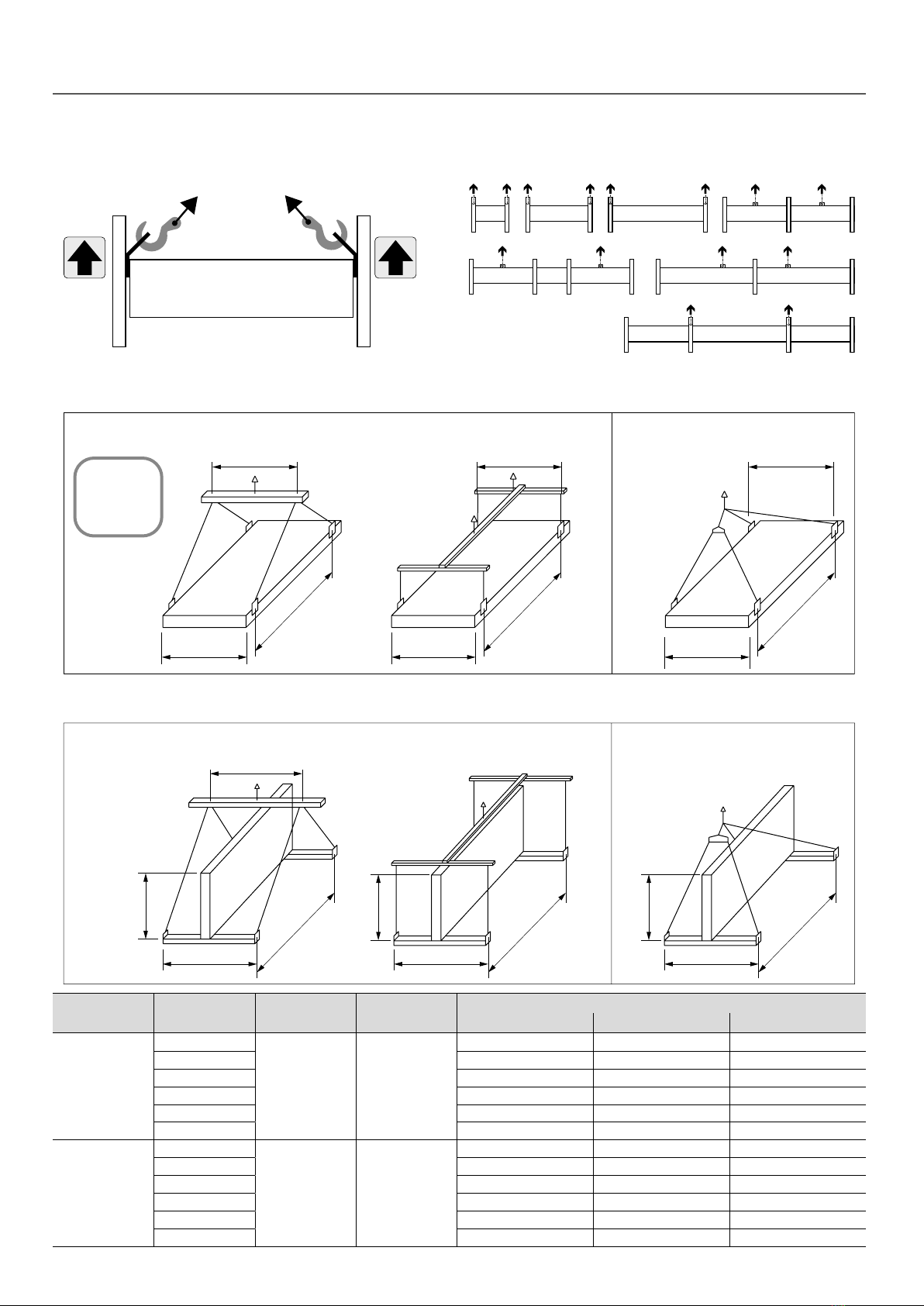
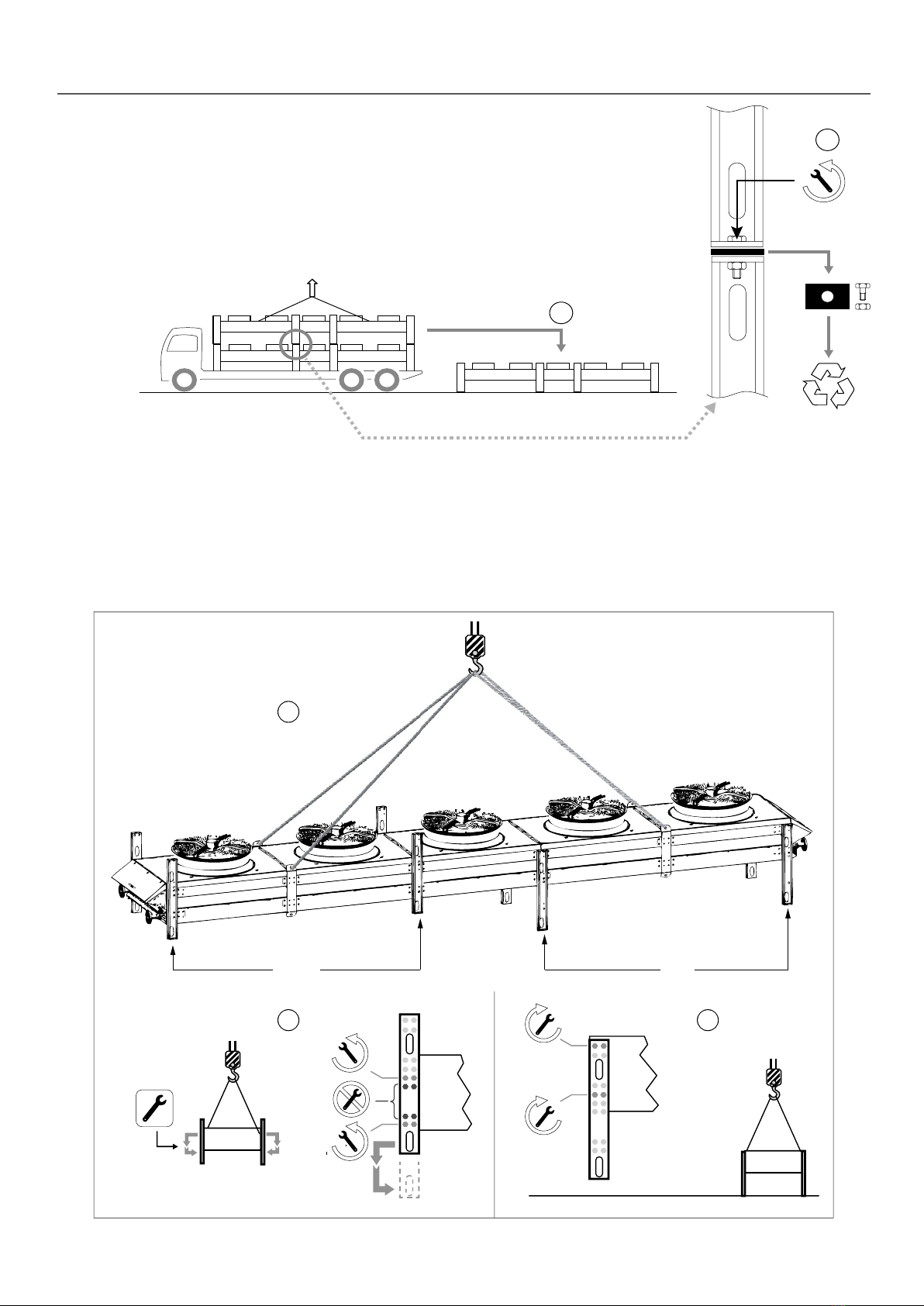
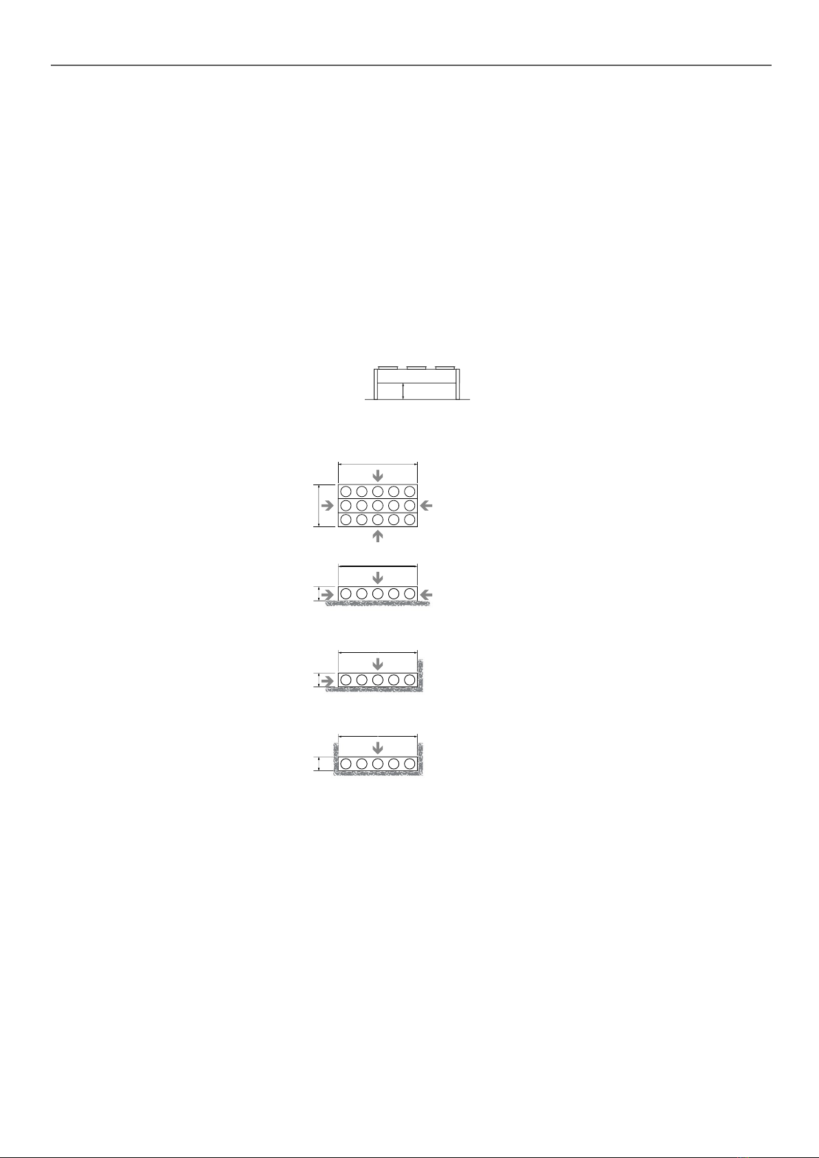
■Use the mounting holes and, if necessary, reinforce the anchoring system according to the wind conditions (particularly for vertical units).
■If the unit needs to be installed on a framework, this structure must be calculated based on the weight of the unit during operation
(full), equipped with all its accessories.
■If using rubber mounts, use a rigid frame which locks the feet together.
■If objects or hail fall on the unit, there is a risk that the finned components may be damaged (horizontal forced-draught units). Take
appropriate steps to protect it, by adding a protective screen, for example.
■If there is a risk of freezing while the system is operating, use a device designed to prevent this.
■Install venting and draining devices and shut-off valves.
■Connect the piping to earth in accordance with an overall study of the installation.
■For any accessories, refer to the specific guides.
9 - CONNECTIONS
9.1 - Electrical connection
■All wiring must be connected in accordance with the regulations that apply to the installation site (e.g. NF C 15100 in France).
■In all cases, refer to the "ELECTRICAL CONNECTIONS" document or wiring diagram attached to the unit.
■ Follow the electrical supply specications indicated on the data plate.
■The phase unbalance must not exceed ±2% for voltage.
If any of the above requirements are not met, immediately contact your energy supplier and make sure the unit is not switched on until
the necessary corrective actions have been taken. Failure to do so will automatically void the warranty.
It is your responsibility to protect the unit from mains voltage spikes and voltage spikes caused by lightning. Depending on the geographic
location and the type of mains network (buried or overhead), local regulations may require that a lightning rod be installed. Failure
to comply with the requirements of standards in force in the country of installation (e.g. NF C 15100 in France) will void the warranty.
-Before making any connection, check that the power supply cable is not powered on.
The terminal boxes on the motors for units without the terminal box or electrical cabinet option must be directly connected taking all
the necessary precautions in order to avoid:
-electrical connection errors which can damage the motors or impair performance
-water ingress in the terminal boxes (e.g. if the cover is not closed properly) which damages the motors
-people falling from a height when making electrical connections for units installed high up
Fluid connection
■Never introduce foreign bodies into the circuit.
■The connection pipes and the regulation or insulation equipment must be set up and supported so as to ensure they do not exert
any force on the coil piping (pressure, torsion or exion). It is recommended to use exible connectors on the connections to prevent
water hammer.
■Positioning of pipes: connect all piping on the unit (see dimensional drawing)
■If brazed/welded connections are used, take appropriate precautions to ensure that welding residues do not enter the circuit.
Special note for condensers:
■Refrigerant connections: The refrigerant connections between the condenser and the internal machine, as well as the leak tests,
must be carried out by a specialist using a method in accordance with best current practices and applicable standards and
regulations. Units are delivered pre-charged with nitrogen at 0.5 bar with piping blanked.
-Blanking with brazed plugs: remove the plugs by heating them with a blowtorch
-Blanking with pressed metal: use a pipe cutter to cut off the end of the pipe no more than 10 mm from the end.
■Inlet/outlet according to stickers afxed to the manifold close to the orice.
■On grounds of hygiene, SAWING AND GRINDING ARE FORBIDDEN. Use a pipe cutter.
9.2 - Connecting a speed regulator
■ A regulator must be commissioned by a specialist, as an incorrect choice/conguration could cause electromagnetic interference
and damage to the motors. Minimum precautions:
-Use a shielded cable upstream and downstream of the regulator.
-The frequency must be between 25 and 50 Hz.
-Fit a DU/DT filter between the speed regulator and the fans.
10

10 - OPERATION
10.1 - First commissioning
■Read the guides for commissioning any accessories very carefully and follow all advice.
■Check that the supply voltage corresponds to that given on the data plate.
■Retighten the connections of the electrics box.
■Switch the unit on and check that all the fans are turning in the correct direction (direction of rotation shown on the labels).
In the event of abnormal noise coming from the fan motor assemblies, immediately switch off the power supply and contact us.
■Ensure that the hydraulic circuit(s) are clean.
■Start charging by bleeding the air remaining in the circuit using the vents provided in the top section.
■Start increasing the pressure, then check that the pipe connections are fully sealed.
10.2 - In the event of faults
Please contact us if you require any help. Before contacting your CIAT agency, please check the following points:
-Are all fans turning in the correct direction? (check this against the labels)
-Is the supply voltage correct?
-Are the motors running at the correct speed? (check the input current)
-Has the uid direction been reversed during connection of the coil?
-Are the ns of the coil clogged?
-Are there any issues relating to air recycling or a poor air supply?
10.3 - Recommendations for use
Scaling and corrosion have a very negative effect on the operation and service life of the units. Therefore, only use treated
water or authorised fluids (check the compatibility of any additives with the drycooler's materials).
11 - AC FAN MOTOR ASSEMBLIES
11.1 - AC motor protection
■All the motors are equipped with a thermal cut-out, which is available in the motor terminal box. Wiring for the thermal cut-out is
optional
11.2 - Fan with AC motor (3-ph 230 V/400 V 50 Hz)
■ On a 3-ph/400 V/50 Hz network, the motors have 2 rotation speeds, via star (Y) or delta connection (Δ).
-Low speed with Y connection
-High speed with Δ connection
■ On a 3-ph/230 V/50 Hz electrical network, the motors have 1 rotation speed via delta connection (Δ):
-Low speed with Δ connection
11.3 - Fan with AC motor 3-ph 208 V and 3-ph/400 V to 480 V 60 Hz
■ On a 3-ph 208 V/60 Hz and 230 V/50 Hz electrical network, the motors have 1 rotation speed via delta connection (Δ).
■On a 3-ph/400 to 480 V/60 Hz electrical network, the motors have 1 rotation speed via star connection (Y):
Impeller diameter mm 910 800
Motor type B9A B9B B9C B8A B8B B8C B8D
3-ph 208 V/60 Hz supply ΔΔΔ - - Δ Δ
3-ph/400 to 480 V/60 Hz supply YYYYYYY
Speed(s) rpm 1100 1000 800 1100 1050 840 520
Weight of impeller + motor kg 28 25 25 23 23 19 19
Weight of fan motor assembly kg 69 66 66 51 51 47 47
Min. room temperature for storage °C -40
Min. operating temperature °C -40
Insulation class F
Sealing class IP 54
Number of starts Max. 50 / hour
11

12 - EC FAN MOTOR ASSEMBLIES
12.1 - EC motor protection
■These motors feature integrated protection and monitoring devices. They are protected against thermal overload of the electronic
components and motors, and against any failure of the Hall effect sensors to analyse the position of the rotor.
■These faults are indicated by a change of state in the KL2 fault relay (terminals COM-NO-NC). This is a potential-free changeover
relay, with a breaking capacity of 2 A/250 VAC cos phi = 1.
■List of faults:
-In the event of a thermal overload on the motor/electronic controls, or a Hall effect sensor fault:
The fan stops and cannot be restarted. The fault is indicated by a change of state on the KL2 relay. The fan can only be
restarted by powering off for 20 seconds then powering back on again (after the source of the fault has disappeared, otherwise
the cycle restarts).
-Rotor blockage:
In the event of accidental rotor blockage, the fault is indicated by a change of state on the KL2 relay. When the blockage is
cleared, the fan automatically restarts.
-Under voltage:
The motor accepts a nominal voltage/frequency range of 380 to 480 V/50 to 60 Hz with no notable modication to a handling
performance. Between 380 and 290 V, the fan continues to operate with degraded performance. If the voltage drops below 290
V for 5 seconds, the motor stops. The fault is indicated by a change of state on the KL2 relay. The motor will restart when the
voltage returns to its nominal value.
-Absence of phase:
If one of the 3 phases is absent for more than 5 seconds, the motor stops. The fault is indicated by a change of state on the
KL2 relay. The motor will automatically restart 10 - 40 seconds after the 3 phases return. Phase inversion has no effect on the
direction of rotation of the motor.
12.2 - Fan with EC motor (3-ph 380 V to 480 V 50/60 Hz)
■On a 3-ph/380-400 V/50/60 Hz network, EC motors will have different rotation speeds depending on the control signal.
Impeller diameter (mm) 910 800
Supply voltage 3-PH/380 - 480 V/50/60Hz supply
Control signal 0/10 V or 4/20 mA
Motor type E9A E9B E8A E8B E8C
Max. speed(s) rpm 1000 1100 740 510 700
Weight of impeller + motor kg 25 - 20 9 -
Weight of fan motor assembly kg 65 45 40 38 26
Min. room temperature for storage °C -40
Min. operating temperature °C -25 -35 -25 -40 -35
Insulation class F
Sealing class IP 54
Number of starts Max. 50 / hour
13 - ATEX (STANDARD) FAN MOTOR ASSEMBLIES
Collar diameter mm 1000 800
Impeller diameter mm 976 776
3-PH/230 V supply -Δ
3-PH/400 V supply ΔY
Max. speed(s) rpm 1450 1450
Weight of fan motor assembly kg 115 60
Min. room temperature for storage °C -40
Min. operating temperature °C -40
Insulation class F
Sealing class IP 55
Number of starts Max. 50 / hour
On request:
Other fans (speed/voltage etc.) available
12

14 - MAINTENANCE
14.1 - Recommendations for maintenance
■Make sure power to the unit has been disconnected before servicing.
■Reduce the temperature and pressure before carrying out any work on the bundle.
■ For drycoolers with an expansion vessel, lower the temperature before opening the ller cap (valve cap).
■ Do not make any modications without our agreement.
■Do not walk directly on the unit.
■ Depending on the type of uid (e.g. water without anti-freeze), take precautions to prevent the risk of freezing, which would destroy
the coil. As standard units cannot be completely drained by gravity, protect from freezing as follows:
1. Drain the circuit using the bleed nozzles and the vent located on the manifolds or pipes.
2. Circulate compressed air through the circuit until all water has been removed.
3. Fill the circuit with anti-freeze and close the circuit.
■For regulated units, do not forget the mandatory inspections.
■In winter, do not allow snow to accumulate around and on top of the unit.
■Periodically check the condition of the coatings and apply touch-ups as needed.
14.2 - Maintenance frequency
ACTION FREQUENCY
Retighten nuts and bolts on fan motor assemblies (grille, motor). 6 months
Check and retighten the packing boxes and mounting bolts on the terminal boxes, if necessary. 6 months
Clean the coil. 1 year (1)
Retighten the electrical connections. 1 month after system start-up then 1 year
Retighten all visible nuts and bolts. 1 year
Check for corrosion to the panelling and that the safety labels and name plate label are present. 1 year (1)
Clean the louvres on the electrical cabinet (optional) 1 year
Expansion vessel (optional): check that all devices work correctly and check the sealing of all couplings. 1 year
Check the electrical cables. 5 years
(1) Frequency to be adapted to the environmental conditions.
14.3 - Information relating to condensers
The sealing test must be carried out in compliance with EC regulation no. 517/2014 relating to certain greenhouse gases.
R410A, R134a and R407C are refrigerant gases with the following environmental impact:
1/ No impact on the ozone layer.
They have an ODP (Ozone Depletion Potential) index of 0
2/ Impact on the greenhouse effect: Global Warming Potential (GWP) of each gas.
- R410A -------- GWP = 2088
- R407C -------- GWP = 1800
- R134a -------- GWP = 1430
-Users must ensure that periodic leak testing is carried out by qualied personnel based on the number of tonnes of CO2
equivalent:
≥ 5 tCO2eq ≥ 50 tCO2eq ≥ 500 tCO2eq
Frequency of check
Without leak detection system Every 12 months Every 6 months Every 3 months
With leak detection system Every 24 months Every 12 months Every 6 months
Refrigerant
charge*
R410A (GWP = 2088) ≥ 2.39 kg ≥ 23.9 kg ≥ 239 kg
R407C (GWP = 1800) ≥ 2.77 kg ≥ 27.7 kg ≥ 277 kg
R134a (GWP = 1430) ≥ 3.49 kg ≥ 34.9 kg ≥ 349 kg
* The refrigerant charge and the number of tonnes of CO2equivalent will be given by the installer.
- Users of any system subject to leak testing are required to keep a log of the quantities and types of uids used, (added or
recovered), and to include the dates and results of leak tests, as well as the name of the technician and the technician's company.
-A leak test must be carried out one month after any leak repairs.
-System users are responsible for collecting used refrigerant and having it recycled, regenerated or destroyed.
13

14.4 - Cleaning the coils
■Switch off the unit.
■ If the unit is tted with a "protective screen" option, remove this to access the coils.
■ If the ns are damaged, straighten them using a comb.
■In the event of minor fouling (non-clogging dry residue or dust, leaves, wires, etc.):
-Counter-ow supply air: dry air up to 30 bar.
-Where possible, periodically reversing the ow of air generated by the fans can prevent this. This operation is not possible if the
unit is equipped with EC motors.
■In the event of moderate fouling (moderate clogging due to dry residues, damp dust or grass, insects, etc.):
-Use a high-pressure (HP) steam cleaner with a at jet nozzle (25°).
-Max. pressure 100 bar
-Steam: max. 140°C
-Min. distance between the nozzle and the ns = 200 mm
-Cleaning uid: municipal water with pH neutral detergent (pH 7). Avoid alkaline detergents.
-Flushing with clean water using the same adjustment parameters.
■IMPORTANT: the use of detergent is prohibited for cleaning ns with a BLYGOLD®, ALTENA®or HERESITE®coating.
Recommendations to follow when using a HP cleaner
1. Ensure the high-pressure cleaner has reached its correct temperature. Check that the
uid exiting the nozzle is steam rather than liquid.
2. Hold the high-pressure cleaner's lance at a distance greater than that recommended, then
move forward into the working position.
3. Direct the at jet created by the nozzle onto the surface of the ns and perpendicular to
them. An angled position risks pushing the ns together and a parallel position risks pushing
them apart.
4. To prevent residue from being pushed inside the nned block, it is often useful to perform
an initial wash against the air ow direction (at the discretion of the operator and depending
on the fouling level).
5. Some detergents may damage the unit's paintwork.
14.5 - Removing and retting a fan
■The removal of a fan is a simple operation, however special care must be taken during handling, in particular:
-Do not pull on the blades.
-Place the fan motor assembly on a safe surface away from areas of activity.
-If the unit is to be shipped, provide the necessary protection and packing materials.
-Do not remove the panel.
■The fan must be repaired if any of the blades are bent.
Operating procedure for motor type A9A, A9C, A8A, A8B,E9A, E8A, E8B, M9, M8, B9A, B9B, B9C, B8A, B8B, B8C and B8D:
Switch off the power supply using the mains switch or maintenance switch (optional).
1. Remove the cover from the motor's terminal box.
2. Disconnect the wires, marking the terminals to facilitate rewiring.
3. Loosen the cable gland(s) on the terminal box and pull out the cable. Remove the
clamps connecting it to the fan support arm.
4. Remove the 4 M8 bolts mounting the fan on the collar (T40 torx type spanner)
WARNING: do not unscrew the motor mounting bolts.
Remove the fan using the lifting lugs.
■ When retting, position the fan on the 4 collar inserts then carry out the operations in the
reverse order to removal, ensuring only the M8 bolts provided are used (tightening torque 16 Nm).
■Before turning the unit back on, make sure:
-the ends of the blades do not touch the collar (centring of the blades in their collar): rotate the impeller by hand.
-the wiring is correct and the terminals are properly tightened.
-the motor terminal box seal is correctly in place and the screws which secure it in place are correctly tightened to a torque of 1.5
± 0.2 Nm (risk of rainwater ingress).
-the cable glands are properly tightened.
NO
NO
YES
14 - MAINTENANCE
14

14 - MAINTENANCE
Operating procedure for motor type A9B, A9D, A8C, E9B and E8C:
Switch off the power supply using the mains switch or maintenance switch (optional).
■Disassembly
1. Remove the protective grille from the fan.
2. Remove the cover from the motor's terminal box.
3. Disconnect the wires, marking the terminals to facilitate rewiring.
4. Loosen the packing box(es) on the terminal box and pull out
the cable,
remove the clamps connecting the cable to the fan support arm.
5. Remove the 12 fan mounting bolts on the unit.
6. Remove the fan using the lifting hooks which should be fed through
the ø12 mm holes.
BE CAREFUL TO ENSURE the handling hooks are positioned diametrically opposed to each other on the widest parts of the rim of
the collar on the fan.
■To reassemble, position the fan on the 12 inserts of the unit then repeat the operations in reverse order to disassembly, taking care
only to use the screws supplied:
-M8x25 screws & at washer for V-shaped units (tightening torque 12 Nm).
-M10x25 screws for atbed units (tightening torque 24 Nm).
M8x25 screws & at washer Torx screws for the protective
grille (tightening torque 6 Nm)
M10x25 screws
■Before turning the unit back on, make sure:
-the ends of the blades do not touch the collar (centring of the blades in their collar): rotate the impeller by hand.
-the wiring is correct and the terminals are properly tightened.
-the motor terminal box seal is correctly in place and the screws which secure it in place are correctly tightened to a torque of
2.5 for EC motors and 1.3 Nm for AC motors. (risk of rainwater ingress).
-the cable glands are properly tightened.
8 x Ø12 mm holes to be
used to feed through the
lifting hooks
Do not use the holes
located in the dark areas
15

15 - MAINTENANCE SWITCHES OPTION
Function
■The maintenance switch can be used to work on a fan motor assembly without interrupting the operation of the device. It cuts the
power supply to the closest motor, and the other motors remain powered on and operate normally.
■ The maintenance switch is not a safety device; the installer is still obliged to t an emergency stop on the installation.
Precautions
■The operator must padlock the locking device to prevent the unit being switched back on by another person.
■Warning: pressing the switch only affects the associated motor. Bear in mind that, even if the unit appears to have stopped completely,
it may restart at any time, and all the other components are still powered on.
Specications
■Sealing: IP65
■Minimum storage temperature: -25°C
■Cable routing diameter: M20
Electrical connection
■See connection sheet.
■For units with the "ELECTRICAL CABINET" or "ELECTRICS BOX" option, the maintenance switches are connected in the factory.
16 - PROTECTION CABINET OPTION
Function
■Protects the motors
Power supply
■See connection sheet or wiring diagram supplied with the cabinet.
Limits of use
■Ambient air:
-Storage temperature: -40/+60°C
-Operating temperature: -25/+55°C
Components
■Packing boxes are provided for the installer on the base of the cabinet.
■ A padlockable front disconnect switch, with auxiliary contact, tted with a device requiring the power supply to be switched off before
the door is opened. This works as an emergency stop.
■One thermal-magnetic circuit breaker for each motor, padlockable with normally open auxiliary contact.
■1 x 3-stage terminal (1, 2, PE) for each fan line for 0/10 V signal (EC FMA option).
Electrical connection
■The motors are connected to the front of the mounted cabinet on the inlet manifold side.
■For electrical connection, refer to the connection sheet or wiring diagram supplied with the cabinet.
■The cables to use for the power connection must be made from copper. If cables made from other materials, such as aluminium,
are used, bimetallic terminals and connectors or intermediate terminals must be used.
■Make the electrical connections as follows:
-Connection of the power circuit to the main switch.
-Connection of the protective conductor to the earth terminal.
-Connection of 0/10 V signal (EC fan motor assembly option) on 3-stage terminals (1, 2, PE) 1 terminal available for each fan line
-For 2 line machines, a single common value of 0/10 V must be connected on the two terminal strips provided for this purpose.
Information available
■See connection sheet or wiring diagram supplied with the cabinet.
■On dry contacts:
-Switch position feedback
-Fault summary (failsafe)
16

17 - CONTROL CABINET WITH ELECTRONIC BOARD OPTION
Function
■Protects and controls the motors. The control electronic board makes it possible to control the temperature or pressure, monitor
the operating parameters, communicate with certain chillers, diagnose and store faults and communicate with the remote control
console, additional boards or a BMS.
Power supply
■See connection sheet or wiring diagram supplied with the cabinet.
Limits of use
■Ambient air:
-Storage temperature: -40/+60°C
-Operating temperature: -25/+55°C
Components
■Packing boxes are provided for the installer on the base of the cabinet.
■A lockable isolator switch is used as an emergency stop.
■Protection against short circuit provided by 1 or 2 three-pole circuit breakers (ICC = 10 KA)
■Protection against overload: thermal cut-out wiring on electronic board.
■1 x 230 V switch per stage.
■1 Electronic board.
■1 x console with LCD screen optional for condenser.
■ Fluid temperature sensor (drycooler): tted on the outlet pipe (control sensor).
Electrical connection
■Before making any connection, check that the machine's disconnect switch is open.
■The cabinet is connected to the motors and mounted on the front of the unit, on the inlet manifold side.
■For electrical connection, refer to the connection sheet or wiring diagram supplied with the cabinet.
■The cables to use for the power connection must be made from copper. If cables made from other materials, such as aluminium,
are used, bimetallic terminals and connectors or intermediate terminals must be used.
■The electrical connections are to be made as follows:
-Check that the power supply cable is not powered on before connecting the power circuit on the disconnect switch.
-Connection of the protective conductor to the earth terminal.
-Connection for automatic operation control
-Connection for changing the setpoint.
-Connection for fan forced operation
■Outdoor temperature sensor (drycooler):
-The machine must be installed to enable the outdoor temperature sensor to be positioned on the nearest north façade of the
building. Failing this, the sensor must be positioned on the north face of the unit, away from any air ows (e.g. fan).
If none of these criteria can be met, the customer must put a met mast in place. (Not supplied)
-The sensor cable must be protected from any harmful external elements.
-Make sure the outdoor sensor is not exposed to direct sunlight, and place it in a vertical position:
Electronic board functions.
■See the user manual for the electronic board.
17

Options
■400/230 V transformer for the control circuit, for 400 V 3-phase supplies without neutral.
■ Water loop temperature sensor (drycooler) to be tted with free-cooling upstream of the valve: Fluid 90 °C max. – 6-m cable – G
1/2" pocket.
■ Pressure sensor (condenser): 35 bar max. (optional 50 bar max.) – mounted on the "are" union on the inlet piping.
■Remote control console: max. distance: 1000 m. To be installed locally.
Dimensions (L x H x D): 102 x 235 x 55 mm.
■Relay board: this has potential-free (dry) contacts for remotely displaying the following parameters: unit operation, sensor faults
and fan stage faults. The boards must be installed in a cabinet.
■Electrical power measurement.
Ventilation
■ Louvres with lters are tted on the sides of the cabinet. As an option, a fan may be added for use from 45 to 55°C.
Heating
■As an option, a heater connected to a temperature sensor may be added for use from -20 to -40°C.
Humidity
■As an option, a heater connected to a humidity sensor may be added for use above 60% humidity.
Information available
■See connection sheet or wiring diagram supplied with the cabinet.
■On dry contacts:
-Switch position feedback
-Operating information
-Fault summary (failsafe)
18 - ELECTRICS BOX OPTION
Function
■The electrics box centralises the wiring and fans on the front of the unit.
Specications
■Ambient air:
-Storage temperature: -40/+60°C
-Operating temperature: -25/+60°C
■Sealing: IP55
■Cable routing diameter: M20
Components
■Packing boxes are provided for the installer on the base of the box.
■1 x 3-stage terminal (U1, V1, W1) for each fan for phase connection.
■1 x 3-stage terminal (1, 2, PE) for each fan for thermal cut-out connection.
■1 x 3-stage terminal (1, 2, PE) for each fan line for 0/10 V signal (EC FMA option).
■For 2 line machines, a single common value of 0/10 V must be connected on the two terminal strips provided for this purpose.
17 - CONTROL CABINET WITH ELECTRONIC BOARD OPTION
18

19 - STAGING FOR CONTROL CABINET OPTION
1 or 2 circuits
per coil
2 circuits
per coil
1 circuit
per coil
Key :
M
01
Number of motors
1
Number of stages
19

20 - OPTION FOR CONTROL CABINET CONTROLLED BY THE CHILLER
(AUX1)
Function
■Protects and controls the motors. The electronic board is used to communicate with certain chillers with integrated boards to control
the unit according to the temperature or pressure.
Power supply
■See connection sheet or wiring diagram supplied with the cabinet.
Limits of use
■Ambient air:
-Storage temperature: -40/+60°C
-Operating temperature: -25/+55°C
Components
■Packing boxes are provided for the installer on the base of the cabinet.
■A lockable isolator switch is used as an emergency stop.
■Protection against short circuit provided by 1 or 2 three-pole circuit breakers (ICC = 10 KA)
■Protection against overload: thermal cut-out wiring on electronic board.
■1 x 230-V switch per stage except for variable-speed fans (EC) which do not have a switch.
■1 Electronic board.
■ Temperature sensor (drycooler): tted on the outlet pipe (control sensor).
Electrical connection
■Before making any connection, check that the machine's disconnect switch is open.
■The cabinet is connected to the motors and mounted on the front of the unit, on the inlet manifold side.
■For electrical connection, refer to the connection sheet or wiring diagram supplied with the cabinet.
■The cables to use for the power connection must be made from copper. If cables made from other materials, such as aluminium,
are used, bimetallic terminals and connectors or intermediate terminals must be used.
■The electrical connections are to be made as follows:
-Connection of the protective conductor to the earth terminal.
-Check that the power supply cable is not powered on before connecting the power circuit on the disconnect switch.
■Outdoor temperature sensor: 25-m cable
-The machine must be installed to enable the outdoor temperature sensor to be positioned on the nearest north façade of the
building. Failing this, the sensor must be positioned on the north face of the unit, away from any air ows (e.g. fan). If none of
these criteria can be met, the customer must put a met mast in place. (Not supplied)
-The sensor cable must be protected from any harmful external elements.
-Make sure the outdoor sensor is not exposed to direct sunlight.
Electronic board functions.
■See chiller manual.
Options
■400/230 V transformer for the control circuit, for 400 V 3-phase supplies without neutral.
■ Water loop temperature sensor (drycooler) to be tted with free-cooling upstream of the valve: 25-m cable, G 1/2" pocket.
Ventilation
■ Louvres with lters are tted on the sides of the cabinet. As an option, a fan may be added for use from 45 to 55°C.
Heating
■As an option, a heater connected to a temperature sensor may be added for use from -20 to -40°C.
Humidity
■As an option, a heater connected to a humidity sensor may be added for use above 60% humidity.
20
Table of contents