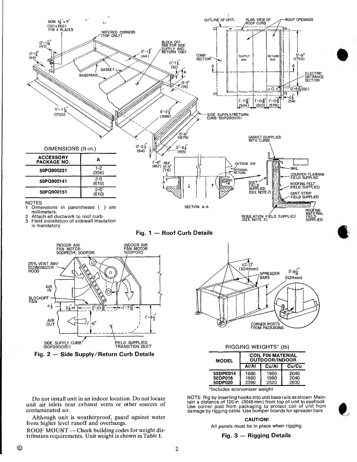
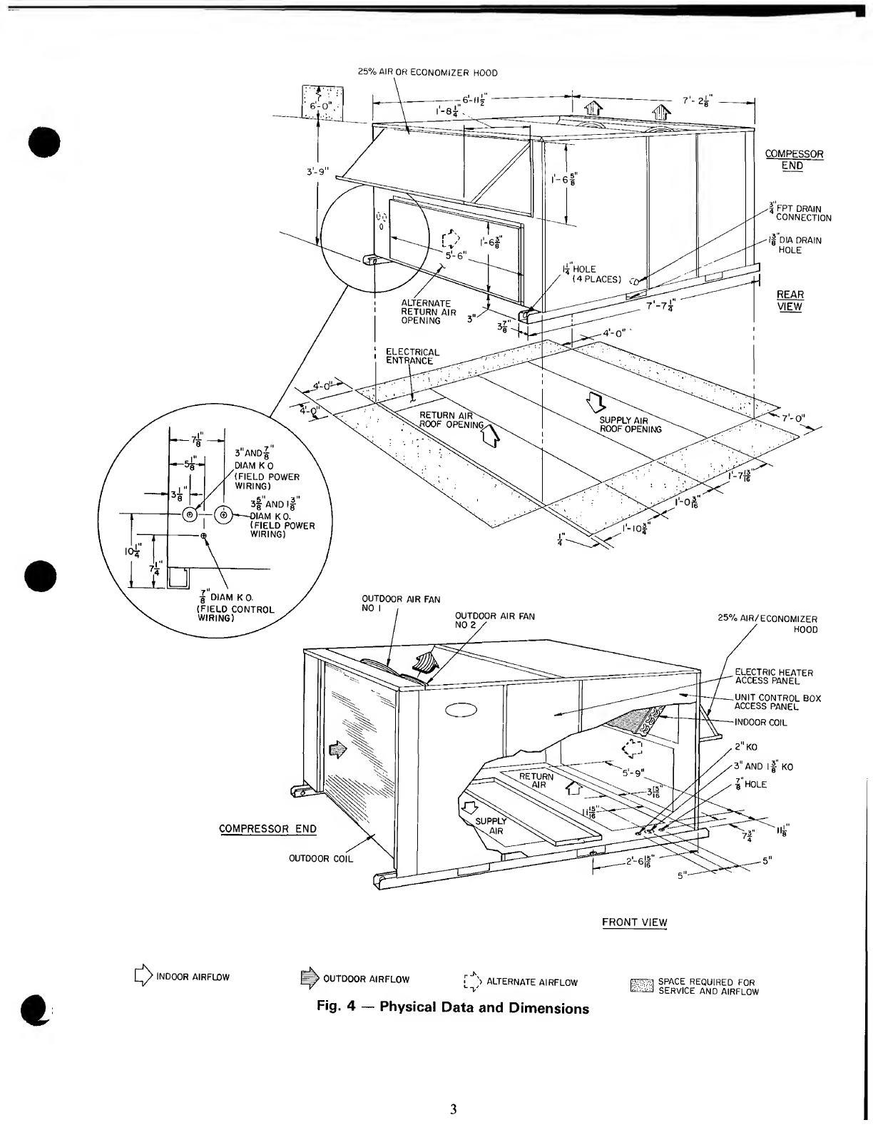
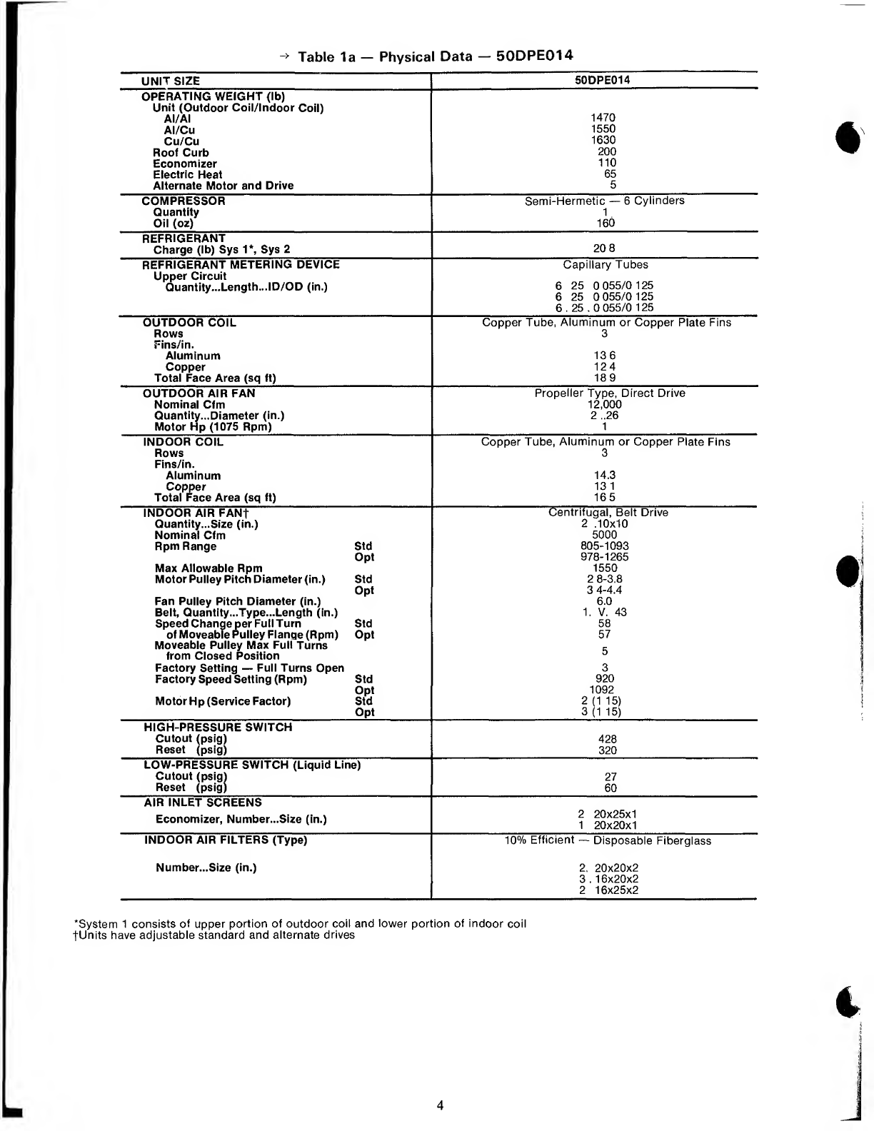
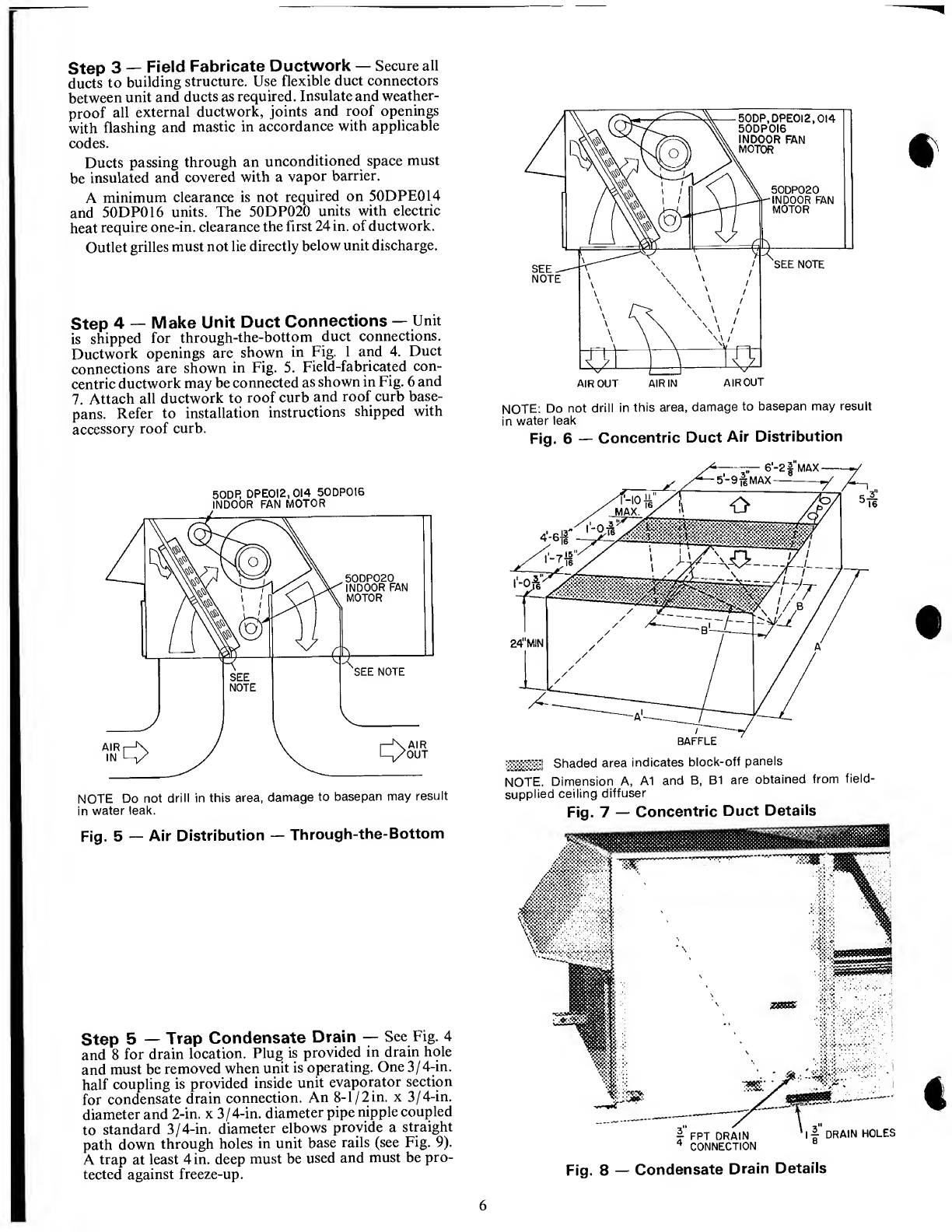
Carrier 50DPE014 Dimensions and installation guide

HEATING
&
COOLING
50DPE014
50DP016,020
Single-Package
Cooling
Units
Installation,
Start-Up
and
Service
Instructions
CONTENTS
Page
SAFETY
CONSIDERATIONS.
!
INSTALLATION
.1-10
Step
1
—
Provide
Unit
Support.
1
•
ROOF
CURB
•
ALTERNATE
UNIT
SUPPORT
Step
2
—
Rig
and
Place
Unit.
I
•
POSITIONING
•
ROOF
MOUNT
Step
3
—
Field
Fabricate
Ductwork.6
Step
4
—
Make
Unit
Duct
Connections.6
Step
5
—
Trap
Condensate
Drain
.6
Step
6
—
Make
Electrical
Connections.7
•
FIELD
POWER
SUPPLY
•
FIELD
CONTROL
WIRING
Step
7
—
Make
Outdoor
Air
Inlet
Adjustments.7
•
MANUAL
OUTDOOR
AIR
DAMPER
•
OPTIONAL
ECONOMIZER
Step
8
—
Install
Outdoor
Air
Hood.
10
START-UP.10-13
SERVICE.14-16
SAFETY
CONSIDERATIONS
Installation
and
servicing
of
air
conditioning
equip¬
ment
can
be
hazardous
due
to
system
pressure
and
elec¬
trical
components.
Only
trained
and
qualified
service
personnel
should
install,
repair
or
service
air
conditioning
equipment.
Untrained
personnel
can
perform
basic
maintenance
functions
of
cleaning
coils
and
filters
and
replacing
filters.
All
other
operations
should
be
performed
by
trained
service
personnel.
When
working
on
air
condi¬
tioning
equipment,
observe
precautions
in
the
literature,
tags
and
labels
attached
to
the
unit
and
other
safety
pre¬
cautions
that
may
apply.
Follow
all
safety
codes.
Wear
safety
glasses
and
work
gloves.
Use
quenching
cloth
for
unbrazing
operations.
Have
fire
extinguishers
available
for
all
brazing
operations.
A
WARNING
,
Before
performing
service
or
maintenance
operations
on
unit,
turn
off
main
power
switch
to
unit.
Electrical
shock
could
cause
personal
injury.
INSTALLATION
Step
1
—
Provide
Unit
Support
ROOF
CURB
—
Assemble
and
install
accessory
roof
curb
in
accordance
with
instructions
shipped
with
this
accessory.
Accessory
roof
curb
and
information
required
to
field
fabricate
a
roof
curb
are
shown
in
Fig.
1
and
2.
Install
insulation,
cant
strips,
roofing
and
flashing
as
shown.
Ductwork
can
be
installed
to
roof
curb
before
unit
is
set
in
place.
Curb
should
be
level.
Unit
leveling
toler¬
ance
is
±
1/16
in.
per
linear
ft
in
any
direction.
This
is
necessary
to
permit
unit
drain
to
function
properly.
Refer
to
Accessory
Roof
Curb
Installation
Instructions
for
additional
information
as
required.
ALTERNATE
UNIT
SUPPORT
—
When
the
curb
cannot
be
used,
support
unit
with
sleepers
using
unit
curb
support
area.
If
sleepers
cannot
be
used,
support
long
sides
of
unit
with
a
minimum
of
3
equally
spaced
4-in.
x
4-in.
pads
on
each
side.
Step
2
—
Rig
and
Place
Unit
—
Inspect
unit
for
transportation
damage.
File
any
claim
with
transporta¬
tion
agency.
Do
not
drop
unit,
keep
upright.
Use
spreader
bars
over
unit
to
prevent
sling
or
cable
damage.
Rollers
may
be
used
to
move
unit
across
a
roof.
Level
by
using
unit
frame
as
a
reference;
leveling
tolerance
is
±
1/16
in.
per
linear
ft
in
any
direction.
See
Fig,
3
for
additional
information.
Unit
weight
is
shown
in
Table
1.
Four
lifting
holes
are
provided
in
ends
of
unit
base
rails
as
shown
in
Fig.
3.
Refer
to
rigging
instructions
on
unit.
POSITIONING
—
Provide
clearance
around
and
above
unit
for
airflow,
safety
and
service
access
(Fig.
4).
Manufacturer
reserves
the
right
to
discontinue,
or
change
at
any
time,
specifications
or
designs
without
notice
and
without
incurring
obligations.
Bookll
|4
PC111
Catalog
No
565-104
PrintedinUSA
Form
50DP-26SI
Pg
1
7-88
Replaces:
50DP-25SI
Tab
|lb|6b

NOM
lf*4"
(32)
x
(102)
TYP.
4
PLACES
ROOF
OPENINGS
Dimensions
millimeters.
Attach
all
ductwork
to
roof
curb
Field
installation
of
sidewall
insulation
is
mandatory
INSULATION
FIELD
SUPPLIED
(SEE
NOTE
3)
Fig.
1
—
Roof
Curb
Details
INDOOR
AIR
INDOOR
AIR
FAN
MOTOR
FAN
MOTOR
50DPE0I4,
50DP0I6
50DP020
(50PQ900I5I)
TRANSITION
DUCT
Fig.
2
—
Side
Supply/Return
Curb
Details
Do
not
install
unit
in
an
indoor
location.
Do
not
locate
unit
air
inlets
near
exhaust
vents
or
other
sources
of
contaminated
air.
Although
unit
is
weatherproof,
guard
against
water
from
higher
level
runoff
and
overhangs.
ROOF
MOUNT
—
Check
building
codes
for
weight
dis¬
tribution
requirements.
Unit
weight
is
shown
in
Table
1.
RIGGING
WEIGHTS*
(lb)
MODEL
COIL
FIN
MATERIAL
OUTDOOR/INDOOR
AI/AI
Cu/AI
Cu/Cu
50DPE014
1880
1960
2040
50DP016
1880
1960
2040
50DP020
2390
2520
2630
‘Includes
economizer
weight
NOTE
Rig
by
inserting
hooks
into
unit
base
rails
as
shown
Main¬
tain
a
distance
of
120
in
(3048
mm)
from
top
of
unit
to
eyehook
Use
corner
post
from
packaging
to
protect
coil
of
unit
from
damage
by
rigging
cable.
Use
bumper
boards
for
spreader
bars
CAUTION!
All
panels
must
be
in
place
when
rigging.
Fig.
3
—
Rigging
Details
2

25%
AIR
OR
ECONOMIZER
HOOD
[D>
INDOOR
AIRFLOW
OUTDOOR
AIRFLOW
f
'>
ALTERNATE
AIRFLOW
Fig.
4
—
Physical
Data
and
Dimensions
^
SPACE
REQUIRED
FOR
SERVICE
AND
AIRFLOW
3

Table
la
—
Physical
Data
—
50DPE014
UNIT
SIZE
50DPE014
OPERATING
WEIGHT
(lb)
Unit
(Outdoor
Coil/Indoor
Coil)
AI/AI
1470
Al/Cu
1550
Cu/Cu
1630
Roof
Curb
200
Economizer
110
Electric
Heat
65
Alternate
Motor
and
Drive
5
COMPRESSOR
Semi-Hermetic
—
6
Cylinders
Quantity
1
Oil
(oz)
160
REFRIGERANT
Charge
(lb)
Sys
1*,
Sys
2
20
8
REFRIGERANT
METERING
DEVICE
Capillary
Tubes
Upper
Circuit
Quantity...Length...ID/OD
(in.)
6
25
0
055/0
125
6
25
0
055/0
125
6.25.0
055/0
125
OUTDOOR
COIL
Copper
Tube,
Aluminum
or
Copper
Plate
Fins
Rows
3
Fins/in.
Aluminum
136
Copper
124
Total
Face
Area
(sq
ft)
189
OUTDOOR
AIR
FAN
Propeller
Type,
Direct
Drive
Nominal
Cfm
12,000
Quantity...Diameter
(in.)
2
..26
Motor
Hp
(1075
Rpm)
1
INDOOR
COIL
Copper
Tube,
Aluminum
or
Copper
Plate
Fins
Rows
3
Fins/in.
Aluminum
14.3
Copper
13
1
Total
Face
Area
(sq
ft)
165
INDOOR
AIR
FANf
Centrifugal,
Belt
Drive
Quantity...Size
(in.)
2
.10x10
Nominal
Cfm
5000
Rpm
Range
Std
805-1093
Opt
978-1265
Max
Allowable
Rpm
1550
Motor
Pulley
Pitch
Diameter
(in.)
Std
2
8-3.8
Opt
3
4-4.4
Fan
Pulley
Pitch
Diameter
(in.)
6.0
Belt,
Quantity...Type...Length
(in.)
1.
V.
43
Speed
Change
per
Full
Turn
Std
58
of
Moveable
Pulley
Flange
(Rpm)
Opt
57
Moveable
Pulley
Max
Full
Turns
from
Closed
Position
Factory
Setting
—
Full
Turns
Open
3
Factory
Speed
Setting
(Rpm)
Std
920
Opt
1092
Motor
Hp
(Service
Factor)
Std
2
(1
15)
Opt
3
(1
15)
HIGH-PRESSURE
SWITCH
Cutout
(psig)
428
Reset
(psig)
320
LOW-PRESSURE
SWITCH
(Liquid
Line)
Cutout
(psig)
27
Reset
(psig)
60
AIR
INLET
SCREENS
Economizer,
Number...Size
(in.)
2
20x25x1
1
20x20x1
INDOOR
AIR
FILTERS
(Type)
10%
Efficient
—
Disposable
Fiberglass
Number...Size
(in.)
2.
20x20x2
3.16x20x2
2
16x25x2
‘System
1
consists
of
upper
portion
of
outdoor
coil
and
lower
portion
of
indoor
coil
tUnits
have
adjustable
standard
and
alternate
drives
4

Table
1b
—
Physical
Data
—
50DP016,020
UNIT
SIZE
50DP016
50DP020
OPERATING
WEIGHT
(lb)
Unit
(Outdoor
Coil/Indoor
Coil)
AI/AI
Al/Cu
Cu/Cu
Roof
Curb
Economizer
Electric
Heat
1470
1550
1630
2i
1
■
1980
2110
2220
00
10
65
COMPRESSOR
Quantity
Oil
(oz)
Semi-Hermetic
1
160
:
—
6
Cylinders
2
160
ea
REFRIGERANT
Charge
(lb)
Sys
1*,
Sys
2
R-22
21.2
R-22
17.0,
17.0
REFRIGERANT
METERING
DEVICE
Upper
Circuit
Quantity...Length...ID/OD
(in.)
Lower
Circuit
Quantity...Length...ID/OD
(in.)
Capillai
6.40.
0.065/0
125
6..20.0
055/0.125
6.20
0
055/0
125
y
Tubes
13.25.0
055/0
125
13
.25
..0
055/0.125
OUTDOOR
COIL
Rows
Fins/in.
Aluminum
Copper
Total
Face
Area
(sq
ft)
Copper
Tubes,
Alumini
3
136
12.4
18.9
jm
or
Copper
Plate
Fins
4
13.6
12.4
22.2
OUTDOOR
AIR
FAN
Nominal
Cfm
Number...Diameter
(in.)
Motor
Hp
(1075
Rpm)
Propeller
Typ
12,000
2
.26
1
ie,
Direct
Drive
11,400
2.
.26
1
INDOOR
COIL
Rows
Fins/in.
Aluminum
Copper
Total
Face
Area
(sq
ft)
Copper
Tubes,
Alumini
3
143
13
1
16.5
um
or
Copper
Plate
Fins
4
14.4
13.1
17.9
INDOOR
AIR
FANf
Quantity...Size
(in.)
Nominal
Cfm
Rpm
Range
Std
Opt
Pulley
A
Pulley
B
Maximum
Allowable
Rpm
Motor
Pulley
Pitch
Diameter
(in.)
Std
Opt
Pulley
A
Pulley
B
Fan
Pulley
Pitch
Diameter
(in.)
Belt,
Quantity...Type...Length
(in.)
Speed
Change
per
Full
Turn
Std
of
Moveable
Pulley
Flange
(Rpm)
Opt
Moveable
Pulley
Max
Full
Turns
from
Closed
Position
Factory
Setting
—
Full
Turns
Open
Factory
Speed
Setting
(Rpm)
Std
Opt
Pulley
A
Pulley
B
Motor
Hp
(Service
Factor)
Std
Opt
Centrifuga
2
..10x10
6000
916-1186
1158-1428
1550
3
4-4
4
4
3-5
3
6.4
1.
.V...45
54
55
5
3.5
970
1240
3
{1
15)
il,
Belt
Drive
2
.12x12
7200
848
1060
1550
32
40
6.6
2
V..45
848
1060
5
(1
15)
HIGH-PRESSURE
SWITCH
Cutout
(psig)
Reset
(psig)
428
320
LOW-PRESSURE
SWITCH
(Liquid
Line)
Cutout
(psig)
Reset
(psig)
27
60
AIR
INLET
SCREENS
Economizer,
Number...Size
(in.)
2.
.20x25x1
1...20x20x1
INDOOR
AIR
FILTERS
(Type)
Number...Size
(in.)
10%
efficient
—
D
2
20x20x2
3.
16x20x2
2.
.16x25x2
isposable
Fiberglass
4
20x20x2
4..
16x20x2
'System
1
consists
of
upper
portion
of
outdoor
coil
and
lower
portion
of
indoor
coil,
except
for
size
020
which
is
intertwined
|016
unit
has
adjustable
standard
and
alternate
drives
The
020
unit
does
not
have
an
alternate
drive,
but
has
2
non-adjustable
pulleys
Pulley
A
is
installed
in
unit,
pulley
B
is
shipped
with
unit
5

Step
3
—
Field
Fabricate
Ductwork
—
Secure
all
ducts
to
building
structure.
Use
flexible
duct
connectors
between
unit
and
ducts
as
required.
Insulate
and
weather¬
proof
all
external
ductwork,
joints
and
roof
openings
with
flashing
and
mastic
in
accordance
with
applicable
codes.
Ducts
passing
through
an
unconditioned
space
must
be
insulated
and
covered
with
a
vapor
barrier.
A
minimum
clearance
is
not
required
on
50DPE014
and
50DP016
units.
The
50DP020
units
with
electric
heat
require
one-in.
clearance
the
first
24
in.
of
ductwork.
Outlet
grilles
must
not
lie
directly
below
unit
discharge.
Step
4
—
Make
Unit
Duct
Connections
—
Unit
is
shipped
for
through-the-bottom
duct
connections.
Ductwork
openings
are
shown
in
Fig.
1
and
4.
Duct
connections
are
shown
in
Fig.
5.
Field-fabricated
con¬
centric
ductwork
may
be
connected
as
shown
in
Fig.
6
and
7.
Attach
all
ductwork
to
roof
curb
and
roof
curb
base-
pans.
Refer
to
installation
instructions
shipped
with
accessory
roof
curb.
50DR
DPE0I2,
014
50DP0I6
INDOOR
FAN
MOTOR
NOTE
Do
not
drill
in
this
area,
damage
to
basepan
may
result
in
water
leak.
Fig.
5
—
Air
Distribution
—
Through-the-Bottom
Step
5
—
Trap
Condensate
Drain
—
See
Fig.
4
and
8
for
drain
location.
Plug
is
provided
in
drain
hole
and
must
be
removed
when
unit
is
operating.
One
3/4-in.
half
coupling
is
provided
inside
unit
evaporator
section
for
condensate
drain
connection.
An
8-1/2
in.
x
3/4-in.
diameter
and
2-in.
x
3/4-in.
diameter
pipe
nipple
coupled
to
standard
3/4-in.
diameter
elbows
provide
a
straight
path
down
through
holes
in
unit
base
rails
(see
Fig.
9).
A
trap
at
least
4
in.
deep
must
be
used
and
must
be
pro¬
tected
against
freeze-up.
NOTE:
Do
not
drill
in
this
area,
damage
to
basepan
may
result
in
water
leak
Fin
6
—
Concentric
Duct
Air
Distribution
Shaded
area
indicates
block-off
panels
NOTE.
Dimension
A,
A1
and
B,
B1
are
obtained
from
field-
supplied
ceiling
diffuser
Fig.
7
—
Concentric
Duct
Details
Fig.
8
—
Condensate
Drain
Details
6

(|")FPT
DRAIN
CONNECTION-l-.
(HALF
COUPLING)
^
r
BASE
RAIL-
LI
TO
TRAP
<J>
Fig.
9
—
Condensate
Drain
Piping
Details
Step
6
—
Make
Electrical
Connections
FIELD
POWER
SUPPLY
—
Unit
is
factory
wired
for
voltage
shown
on
nameplate.
Units
are
provided
with
terminal
block.
When
installing
units,
provide
a
disconnect
per
NEC
of
adequate
size
(Table
2).
All
field
wiring
must
comply
with
National
Electrical
Code
and
local
requirements.
Route
power
lines
through
control
box
end
panel
—
or
unit
basepan
—
(Fig.
4)
to
terminal
connections
as
shown
on
unit
wiring
diagram
and
Fig.
10.
i
l
TBl
S
I
—
[
\d)\
EQUIP
GND
Fig,
10
—
Field
Power
Wiring
Connections
Operating
voltage
to
compressor
must
be
within
voltage
range
indicated
on
unit
nameplate.
On
3-phase
units,
voltages
between
phases
must
be
balanced
within
2%
and
the
current
must
be
balanced
within
10%.
Use
the
following
formula
to
determine
the
%
voltage
imbalance.
%
Voltage
Imbalance
100
x
max
v
°ltag
e
deviation
from
average
voltage
average
voltage
Example:
Supply
voltage
is
460-3-60.
AB
=
452
volts
BC
=
464
volts
AC
=
455
volts
Average
Voltage
=
452
+
464
+
455
1371
=
457
Determine
maximum
deviation
from
average
voltage:
(AB)
457
452
=
5
volts
(BC)
464
-
457
=
7
volts
(AC)
457
-
455
=
2
volts
Maximum
deviation
is
7
volts.
Determine
%
voltage
imbalance:
7
%
Voltage
Imbalance
=
100
xyjyy
=
1.53%
This
amount
of
phase
imbalance
is
satisfactory
as
it
is
below
the
maximum
allowable
2%.
IMPORTANT:
If
the
supply
voltage
phase
im¬
balance
is
more
than
2%,
contact
your
local
electric
utility
company
immediately.
Unit
failure
as
a
result
of
operation
on
improper
line
voltage
or
excessive
phase
imbalance
constitutes
abuse
and
may
cause
damage
to
electrical
components.
Such
operation
would
invalidate
any
applicable
Carrier
warranty.
FIELD
CONTROL
WIRING
—
Install
a
Carrier-
approved
accessory
thermostat
assembly
according
to
installation
instructions
included
with
accessory.
Locate
thermostat
assembly
on
a
solid
wall
in
the
conditioned
space
to
sense
average
temperature.
Route
thermostat
cable
or
equivalent
single
leads
of
no.
18
AWG
colored
wire
from
subbase
terminals
through
conduit
in
unit
to
low-voltage
connections
as
shown
on
unit
label
wiring
diagram
and
in
Fig.
11.
NOTE:
For
wire
runs
up
to
50
ft,
use
no.
18
AWG
insu¬
lated
wire
(35
C
minimum).
For
50
to
75
ft,
use
no.
16
AWG
insulated
wire
(35
C
minimum).
For
over
75
ft,
use
no.
14
AWG
insulated
wire
(35
C
minimum).
Set
heat
anticipator
settings
as
indicated
in
Table
3.
Settings
may
be
changed
slightly
to
provide
a
greater
degree
of
comfort
for
a
particular
installation.
Refer
to
accessory
remote
control
panel
instructions
as
required.
THERMOSTAT
ASSEMBLY
REMOVABLE
JUMPER
r~°—\
gfipHS
|wj]
^
[Yi]
@
[G]
[$
L
[
X
]
is
-
ffl
-
is
-
s
irsntr
_
Enfns
—
iirDi
LOW-VOLTAGE
TERMINAL
BLOCK
IN
UNIT
CONTROL
BOX
Fig.
11
—
Field
Control
Thermostat
Wiring
Step
7
—
Make
Outdoor
Air
Inlet
Adjustments
MANUAL
OUTDOOR
AIR
DAMPER
All
units
(except
those
equipped
with
a
factory-installed
econo¬
mizer)
have
a
manual
outdoor
air
damper
to
provide
ventilation
air.
Damper
can
be
preset
to
admit
up
to
25%
outdoor
air
into
return
air
compartment.
To
adjust,
loosen
securing
screws
and
move
damper
to
desired
setting
then
retighten
screws
to
secure
damper
(Fig.
12).
OPTIONAL
ECONOMIZER
Enthalpy
Control
Setting
(location
is
shown
in
Fig.
13)
—
For
maximum
benefit
of
outside
air,
set
enthalpy
control
to
the
A
setting
(Fig.
14).
7

25%
ADJUSTABLE
AIR
DAMPER
SECURING
SCREWS
BASE
UNIT
Fig.
12
—
25%
Outdoor
Air
Section
Details
COOLING
LOCKOUT
SWITCH
ENTHALPY
CONTROL
DAMPER
MOTOR
FILTERS
ECONOMIZER
CONTROL
BOX
ECONOMIZER
DAMPER
ASSEMBLY
Fig.
14
—
Enthalpy
Control
Assembly
Mixed
Air
Thermostat
Setting
—
Set
mixed
air
thermo¬
stat
in
return
air
compartment
to
desired
temperature
of
air
delivered
to
the
conditioned
space
(not
less
than
35
F
or
condensation
in
unit
will
result).
Damper
Vent
Position
Setting
1.
Set
fan
switch
at
ON
(continuous
fan
operation)
and
close
night
switch
if
used.
2.
Set
system
selector
switch
to
OFF.
3.
Remove
cap
from
vent
adjustment
screw
on
damper
motor
terminal
box
cover.
4.
Turn
adjustment
screw
slowly
until
dampers
assume
desired
vent
position.
Do
not
manually
operate
damper
motor;
damage
to
motor
will
result.
Fig.
13
—
Enthalpy
Control
Location
(Economizer
Damper
Assembly
—
End
View)
8

Table
2
—
Electrical
Data
UNIT
MODEL
VOLTS-PH-HZ
VOLTAGE
RANGE
COMPR
OUTDOOR
FAN
MOTOR
r—
-
INDOOR
FAN
MOTOR
—
FACTORY-
INSTALLED
HEATERS
POWER
SUPPLY
Min
Max
RLA
LRA
Qty
FLA
Hp
FLA
FLA
kW
Min
Ckt
1
MOCP
Amps
(Amps)
50DPE014
208/230-3-60
187
253
49
3
191
2
20
30
20
20
20
20
30
30
3
0
30
7
5
106
7
5
75
7
5
7
5
10
6
106
10
6
10
6
_
_
74/
82
122
122/135
41/
45
74/
82
122
122/135
41/
45
26/31
42*
42/52
14/17
26/31
42*
42/52
14/17
glut
460-3-60
414
508
22
1
86
2
33
2
0
30
2
0
20
20
3
0
30
30
3
4
48
34
34
34
48
48
48
21
39
66
21
39
66
16
30
51
16
30
51
II
575-3-60
518
632
17
9
69
2
26
20
30
2
0
3.0
2
7
3
9
2
7
3.9
37
37
37
37
31
45
32
45
50
50
52
60
50DP016
208/230-3-60
187
253
61
266
2
7
7
30
10
5
74/
82
122/135
163
163/180
26/31
42/52
56*
56/69
16
217
82
225
2
i7/239
-mmm.
460-3-60
414
508
32
0
120
2
33
30
48
_
39
66
96
30
51
73
H
575-3-60
518
632
25
6
96
2
26
30
39
50
49
38
60
68
70
50DP020
208/230-3-60
187
254
49
3
(ea)
153
(ea)
2
77
5
0
16
7
74/
82
122/135
163/180
26/31
42/52
56/69
iiH
460-3-60
414
508
199
(ea)
77
(ea)
2
33
5
0
7
6
39
66
96
30
51
73
i
B
Fuse
only,
unshaded
values
indicate
fuses
or
circuit
breakers
may
be
used
Compr
FLA
Hp
Compressor
Full
Load
Amps
Horsepower
LRA
—
Locked
Rotor
Amps
MOCP
—
Maximum
Overcurrent
Protection
RLA
—
Rated
Load
Amps
*CSA-approved
heaters
are
rated
at
208
volts
only
Q

Step
8
—
Install
Outdoor
Air
Hood
—
The
out¬
door
air
hood
is
common
to
25%
air
ventilation
and
economizer.
If
economizer
is
used,
all
electrical
connec¬
tions
have
been
made
and
adjusted
at
the
factory.
Assemble
and
install
hood
in
the
field.
NOTE:
The
hood
top
cover,
upper
and
lower
filter
retainers,
hood
drain
pan
and
filter
support
bracket
are
secured
to
the
top
crate
above
the
condenser
fans.
The
screens,
hood
side
panels,
remaining
section
of
filter
support
bracket
and
all
other
hardware
are
in
a
package
located
inside
the
return-air
filter
access
panel
(Fig.
15
and
16).
OUTDOOR
AIR
HOOD
AND
MOUNTING
BRACKETS
Fig.
15
—
Outdoor
Air
Hood
Component
Location
UNIT
TOP
CRATE
Fig.
16
—
Outdoor
Air
Hood
Components
START-UP
Unit
Preparation
—
Check
that
unit
has
been
installed
in
accordance
with
installation
instructions
and
appli¬
cable
codes.
Compressor
Mounting
—
Loosen
compressor
hold¬
down
bolts
until
sidewise
movement
of
the
washer
under
each
holddown
bolt
head
can
be
obtained.
Do
not
loosen
completely
as
bolts
are
self-locking
and
will
main¬
tain
adjustment.
Internal
Wiring
—
Check
all
electrical
connections
in
unit
control
boxes;
tighten
as
required.
Refrigerant
Service
Valves
—
The
units
have
one
service
valve
on
suction
line,
one
on
discharge
line
and
one
on
liquid
line.
Be
sure
valves
are
open.
Crankcase
Heater(s)
are
energized
as
long
as
there
is
power
to
the
unit.
NOTE:
Unit
power
must
be
on
for
24
hours
prior
to
start-up.
1.
Assemble
hood
top
cover,
side
panels,
upper
filter
retainer
and
drain
pan
(Fig.
17).
2.
Secure
lower
filter
retainer
and
support
bracket
to
unit
as
shown
in
Fig.
17.
3.
Loosen
sheet
metal
screws
for
base
unit
top
cover
located
above
outdoor
air
inlet
opening.
4.
Match
notches
in
hood
top
cover
to
unit
top
cover
screws.
Insert
hood
flange
between
unit
top
cover
flange
and
unit.
Tighten
screws.
5.
Insert
outdoor
air
inlet
screens
and
spacer
in
channel
created
by
lower
filter
retainer
and
filter
support
bracket.
6.
Attach
remaining
section
of
filter
support
bracket.
Table
3
—
Heat
Anticipator
Settings
UNIT
MODEL
VOLTAGES
kW
STAGE
1
STAGE
2
14-17
40
—
208-230/3/60
26-31
40
40
50DPE014
42-52
66
40
1
16
40
—
460/3/60
30
.40
40
51
40
66
26-31
40
66
208-230/3/60
42-52
66
.40
50DP016,020
56-69
66
66
30
40
40
460/3/60
51
40
66
73
.66
66
10

Table
4
—
Air
Quantity
Limits
UNIT
MODEL
MIN
CFM
MAX
CFM
50DPE014
3750
6250
50DP016
4500
7500*
50DP020
5400
9000
Mndoor
Fan
Max
Watts
=
3000
Indoor
Air
Fan
—
Fan
belts
and
pulleys
are
factory
installed.
Belts
are
secured
to
pulleys
with
tape.
Remove
tape
and,
if
required,
adjust
as
described
in
Service,
Indoor
Air
Fan
Adjustment.
50DP020
has
2
non-adjustable
pulleys.
Pulley
A
is
installed
in
unit.
Pulley
B
is
shipped
in
cardboard
box
taped
to
vestibule
below
main
control
box.
Outdoor
Air
Fans
and
Motors
are
factory
set.
Refer
to
Service,
Outdoor
Air
Fan
Adjustment
as
required.
Return
Air
Filters
—
Check
that
correct
filters
are
installed
in
filter
tracks.
See
Table
1.
Do
not
operate
unit
without
return
air
filters.
Outdoor
Air
Inlet
Screens
—
Outdoor
air
inlet
screens
must
be
in
place
before
operating
unit.
Economizer
Section
—
Remove
filter
access
panel.
Check
that
outdoor
air
damper
is
closed
and
return
air
damper
is
open.
Economizer
operation
and
adjustment
is
described
in
Start-Up,
Economizer
Operation;
and
Service,
Econo¬
mizer
Adjustment,
respectively.
Base
Unit
Operation
COOLING
—
Unit
power
on.
System
selector
switch
at
COOL;
fan
switch
at
AUTO.;
thermostat
at
a
setting
below
room
temperature.
50DPEQ14
and
50DP016
—
Compressor
starts
unloaded
on
closure
of
No.
1
contact
in
thermostat.
Additional
rise
in
room
temperature
closes
contact
No.
2
in
thermostat
which
de-energizes
the
unloader
coil.
Compressor
is
now
fully
loaded.
Check
cooling
effects
at
a
setting
below
room
tempera¬
ture.
Check
unit
charge.
Refer
to
Service,
Refrigerant
Charge.
Reset
thermostat
at
a
temperature
above
room
tem¬
perature.
Compressor(s)
will
shut
off.
50DP020
—
Upon
a
rise
in
room
temperature,
cooling
contact
No.
1
in
the
thermostat
closes,
energizing
the
first-stage
cooling
contactor
and
the
indoor
fan
con¬
tactor.
The
first-stage
compressor,
outdoor
fan
motor
and
indoor
fan
motor
start
and
run.
Upon
a
further
rise
in
room
temperature,
cooling
contact
No.
2
in
the
thermostat
closes,
energizing
the
second-stage
cooling
contactor.
The
second-stage
compressor
starts
and
runs.
To
Shut
Off
Unit
—
Set
system
selector
switch
at
OFF
position
or
reset
thermostat
above
room
temperature.
Units
with
Signal-LOC
™
protection
device
shut
down
on
any
safety
trip
and
thermostat
light
comes
on.
Determine
reason
for
safety
trip.
Restart
compressor(s)
by
resetting
circuit
breaker
at
unit.
HEATING
—
Turn
on
main
power
to
unit.
Set
system
selector
switch
at
HEAT,
fan
switch
at
AUTO.;
and
thermostat
at
a
setting
above
room
temperature.
First
stage
of
electric
heater
elements
are
energized
on
closing
of
heating
contact
No.
I
in
thermostat.
On
a
further
fall
of
room
temperature,
heater
contact
No.
2
closes
ener¬
gizing
second-stage
electric
heater
elements.
To
Shut
Off
Unit
—
Set
system
selector
switch
at
OFF.
VENTILATION
AIR
CIRCULATION
(Continuous
Fan)
—
Unit
power
on.
System
selector
switch
at
OFF,
HEAT
or
COOL;
fan
switch
set
at
ON.
Indoor
fan
con¬
tactor
is
energized
through
the
switch
on
the
thermostat,
and
the
indoor
fan
runs
continuously.
AUTOMATIC
CHANGEOVER
(with
Automatic
Changeover
Thermostat)
—
System
selector
switch
set
at
AUTO.
When
temperature
of
conditioned
space
rises
to
cooling
selector
lever
setting,
unit
automatically
switches
from
heating
mode
to
cooling
mode.
When
tem¬
perature
of
the
conditioned
space
falls
to
the
heating
selector
lever
setting,
unit
automatically
changes
from
cooling
mode
to
heating
mode.
The
thermostat
is
inter¬
locked
so
that
cooling
and
heating
systems
do
not
operate
at
the
same
time.
HEAD
PRESSURE
CONTROL
All
units
have
fan
cycling
thermostats
which,
at
55
F,
shut
off
one
outdoor
fan
motor.
This
permits
unit
to
operate
down
to
40
F
outdoor
air
temperature.
Economizer
Operation
—
If
unit
is
equipped
with
modulating
outdoor
air
control
(economizer),
it
should
operate
as
follows:
COOLING
MODE
—
Indoor
and
outdoor
fans
and
com¬
pressor
energize
when
there
is
a
call
for
cooling
and
enthalpy
of
outdoor
air
is
above
enthalpy
control
setting.
The
economizer
damper
moves
to
VENT
position.
Indoor
fan
starts
and
economizer
damper
opens
fully
on
a
first-stage
call
for
cooling
when
enthalpy
of
outdoor
air
is
below
the
enthalpy
control
setting.
Compressor
remains
off.
Compressor
is
energized
and
mechanical
cooling
integrates
with
economizer
cooling
upon
a
second-
stage
call
for
cooling.
If
outdoor
air
temperature
falls
below
50
F,
cooling
lockout
switch
prevents
compressor
from
operating.
Economizer
damper
modulates
when
mixed
air
tem¬
perature
is
below
mixed
air
thermostat
setting.
A
freeze
protection
thermostat
(FPT)
is
located
on
the
indoor
coil.
It
detects
ice
buildup
and
turns
off
the
compressor,
thus
allowing
the
coil
to
clear.
Once
ice
melts,
the
compressor
can
be
re-energized.
HEATING
MODE'
—
Outdoor
air
damper
stays
at
VENT
position
while
indoor
air
fan
runs.
NOTE:
If
fan
switch
is
at
ON
position,
and
room
thermo¬
stat
is
satisfied,
damper
goes
to
ventilation
position.
11

Variable
Volume
Units
—
Units
suitable
for
use
with
variable
volume
air
handling
systems
are
equipped
with
2
electric
unloaders
on
the
compressor.
The
control
panel
for
these
units
(Fig.
18)
consists
of
a
step
controller,
a
proportional
thermostat,
a
7-day
timer
and
a
power
switch.
Before
starting
unit,
open
compressor
service
valves
and
liquid
line
shutoff
valve.
Be
sure
compressor
crank¬
case
heaters
have
been
on
for
24
hours
and
that
crankcase
oil
level
indicates
half
full.
CONTROL
SEQUENCE
CHECKOUT
1.
Turn
on
unit
main
power
supply.
Be
sure
unit
is
ready
to
operate.
2.
Set
variable
volume
control
panel
POWER
switch
at
ON.
3.
If
supply
air
leaving
unit
is
above
50
F
(or
other
field-
set
temperature),
step
controller
will
operate
to
de¬
energize
compressor
unloader
solenoids
(compressor
loads
up)
until
set
temperature
is
achieved.
An
interval
of
13.5
minutes
is
required
to
maximum
loading
position.
Refer
to
unit
label
diagram
for
unloader
sequencing.
Also
see
Fig.
19.
4.
Step
controller,
7-day
timer
and
proportional
thermo¬
stat
are
factory
set
and
adjusted.
If
other
settings
or
changes
in
adjustment
are
required,
refer
to
dis¬
cussion
of
these
items.
SEVEN-DAY
TIMER
ADJUSTMENT
—
Factory
settings
are
ON
—
6:30
A.M.;
OFF
—
7:30
P.M.
for
each
of
7
days.
1.
On
the
timer
dial
face
(Fig.
18),
loosen
the
thumb¬
screws
which
position
the
system
ON
and
OFF
trippers.
2.
Set
trippers
at
desired
system
ON
and
OFF
time
settings
and
tighten
thumbscrews.
Skipping
a
day(s)
is
accomplished
by
removing
trippers
from
the
dial.
3.
Set
the
timer
by
turning
the
dial
face
clockwise
until
fixed
pointer
indicates
correct
day
and
time.
Do
not
turn
dial
face
counterclockwise.
Do
not
move
fixed
pointer.
PROPORTIONAL
THERMOSTAT
—
The
propor¬
tional
thermostat,
Fig.
18,
monitors
temperature
of
the
conditioned
air
leaving
unit.
On
signal
from
the
thermo¬
stat,
sequence
motor
operates
cam
switches
to
load
or
unload
compressor
to
maintain
thermostat
setting.
Thermostat
is
factory
set
at
50
F
±
6
F
but
may
be
reset
between
0°F
and
100F
as
follows:
Temperature
Setting
—
Turn
knob
on
front
of
case
until
pointer
indicates
desired
set
point
temperature.
This
is
the
center
point
of
proportional
range.
Range
Adjustment
—
Remove
cover
and
turn
adjustment
wheel
until
pointer
indicates
desired
range.
If
sequencer
motor
shaft
constantly
moves
back
and
forth,
increase
proportional
thermostat
range
(about
5
F
at
a
time)
until
system
is
stable.
TERMINAL
POWER
PROPORTIONAL
BLOCK
NO
I
SWITCH
THERMOSTAT
Fig.
18
—
Control
Panel,
Variable
Volume
Limits
12

STEP
CONTROLLER
—
The
step
controller
consists
of
a
reversible
electric
motor
which
drives
a
set
of
cams
that
activate
up
to
5
snap-acting
switches.
Each
cam
is
adjust¬
able
to
operate
at
any
point
on
the
160
angular
degrees
of
camshaft
rotation.
The
differential
of
each
system
may
be
adjusted
from
a
minimum
of
5
angular
degrees
to
a
maxi¬
mum
limited
only
by
the
160
angular
degrees
of
camshaft
rotation.
Rotational
direction
is
controlled
by
the
proportional
thermostat
through
the
step
controller
feedback
poten¬
tiometer
and
balancing
relay.
Determining
Switch
Settings
—
Switches
are
factory
set
at
angular
settings
as
shown
in
Fig.
19
(also
shown
on
unit
label
diagram).
To
reset,
if
desired,
determine
angular
differential
for
each
switch
and
between
switches.
Then
determine
minimum
differential
or
throttling
range
of
proportional
thermostat
to
provide
desired
step
con¬
troller
differential
or
throttling
range.
This
range
should
be
wide
enough
to
prevent
rapid
cycling
from
one
capacity
step
to
another.
Then
adjust
cams
to
new
settings
as
required.
MAKE
BREAK
POINT
POINT
Fig.
20
—
Step
Controller
Cam
Adjusting
Details
(Motor
End
View)
Cam
Adjustments
—
The
step
controller
is
shipped
with
cams
set
to
operate
switches
(i.e.
compressor
unloaders)
as
shown
in
Fig.
19.
All
switches
are
closed
(compressor
unloaded).
The
shaft
is
positioned
all
the
way
counter¬
clockwise
(as
viewed
from
motor
end).
Using
the
following
procedure,
first
adjust
all
operating
points
in
one
direction
of
motor
drive.
Then
reverse
motor
direction
and
adjust
switch
differentials.
Use
potentiometer
wiper
as
an
approximate
indicator
of
angular
adjustments
using
angular
displacement
scale
mounted
on
potentiometer
back
plate.
Also
see
Fig.
20.
12
3
4
STEP
CONTROL
SWITCH
Fig.
19
—
Step
Controller
Sequence
1.
Loosen
all
bushing
setscrews
with
a
1/16-in.
Allen
wrench.
Loosen
all
cam
hex
screws
with
a
3/16-in.
open-end
wrench.
If
setscrews
are
not
accessible
from
top
of
controller,
operate
motor
to
rotate
cams
and
bushings
by
shorting
terminals
R
and
B
for
counterclockwise
rotation
and
terminals
R
and
W
for
clockwise
rotation.
2.
Momentarily
de-energize
motor
to
permit
motor
to
recycle
to
start
position.
Jumper
terminals
R
and
W
to
run
motor
camshaft
to
desired
position
for
operating
first
switch.
Stop
motor
in
this
position
by
removing
jumper
between
terminals
S
and
T.
3.
Starting
with
first
switch,
turn
cam
clockwise
until
switch
makes
an
audible
“click”
as
roller
moves
up
cam
rise
to
higher
level.
This
is
the
operating
point.
Lock
bushing
setscrews.
4.
Set
operating
point
of
each
of
remaining
switches
in
like
manner.
Advance
motor
by
momentarily
jumper¬
ing
terminals
S
and
T.
5.
Set
switch
differential
by
reversing
motor
(short
terminals
R
and
B)
and
running
it
to
desired
break
point.
Stop
motor
at
this
point
by
de-energizing
power
at
LI
(POWER
switch
off).
Start
at
last
switch
and
progress
to
first
switch.
Move
differential
cam
clockwise
so
that
roller
is
on
high
part
of
cam.
Be
sure
that
switch
is
at
make
position.
To
check
this,
manually
lift
roller
assembly
to
make
switch.
Move
differential
cam
counterclock¬
wise
until
roller
drops
to
low
level
of
cam.
At
this
point,
switch
should
break.
Lock
the
hex
screw.
6.
Check
settings
by
performing
Control
Sequence
Checkout.
7.
If
115-volt
to
step
controller
is
de-energized,
timer
recycles
to
start
point
when
power
is
restored.
13

SERVICE
A
WARNING
Before
performing
service
or
maintenance
operations
on
unit,
turn
off
main
power
switch
to
unit.
Turn
off
accessory
heater
power
switch
if
applicable.
Elec¬
trical
shock
could
cause
personal
injury.
Cleaning
—
Inspect
unit
interior
at
beginning
of
each
heating
and
cooling
season
or
as
operating
conditions
require.
Remove
unit
top
panel
and/or
side
panels
for
access
to
unit
interior.
INDOOR
COIL
—
Clean
with
a
commercial
coil
cleaner.
OUTDOOR
COIL
—
Clean
outdoor
coil
annually
or
as
required
by
location
or
outdoor
air
conditions.
Inspect
coil
monthly
—
clean
as
required.
CONDENSATE
DRAINS
—Check
and
clean
each
year
at
start
of
cooling
season.
In
winter,
keep
drains
and
traps
dry
or
protect
against
freeze-up.
FILTERS
—
Clean
or
replace
at
start
of
each
heating
and
cooling
season,
or
more
often
if
operating
conditions
require.
Refer
to
Table
1
for
type
and
size.
OUTDOOR
AIR
INLET
SCREENS
—
Clean
screens
with
steam
or
hot
water
and
a
mild
detergent.
Do
not
use
throwaway
filters
in
place
of
screens.
Lubrication
COMPRESSORS
—
Each
compressor
is
charged
with
correct
amount
of
oil
at
the
factory.
FAN
SHAFT
BEARINGS
—
No
lubrication
required.
Bearings
are
permanently
lubricated.
FAN
MOTOR
BEARINGS
—
No
lubrication
of
out¬
door
fan
or
indoor
blower
motors
are
required
for
first
5
years
of
operation.
Annually
thereafter,
clean
and
repack
bearings
with
a
suitable
bearing
grease.
5.
Set
movable
flange
at
nearest
keyway
of
pulley
hub
and
tighten
setscrew.
(See
Table
1
for
speed
change
for
each
full
turn
of
pulley
flange.)
To
align
fan
and
motor
pulleys,
loosen
fan
pulley
set¬
screws
and
slide
fan
pulley
along
fan
shaft.
Make
angular
alignment
by
loosening
motor
from
mounting
plate.
Fig.
21
—
Indoor
Air
Fan
Pulley
Adjustment
(50DPE014
and
50DP016)
To
Adjust
Belt
Tension
—
Loosen
fan
motor
pivot
bolts.
Move
motor
mounting
plate
up
or
down
for
proper
belt
tension
(1/2-in.
deflection
with
one
finger)
and
tighten
pivot
bolts.
Adjust
lock
bolt
and
nut
on
mounting
plate
to
secure
in
fixed
position.
Outdoor
Air
Fan
Adjustment
(Fig.
22)
—
Shut
off
unit
power
supply.
Remove
fan
top
grille
assembly
and
loosen
fan
hub
screws.
Adjust
fan
height
on
unit
using
a
straight
edge
placed
across
the
fan
orifice,
tighten
setscrews
and
replace
rubber
hubcap
to
prevent
hub
from
rusting
to
motorshaft.
Fill
hub
recess
with
permagum
if
rubber
hubcap
is
missing.
Indoor
Air
Fan
Adjustment
—
Fan
motor
pulleys
are
factory
set
for
speed
shown
in
Table
1.
The
50DP020
units
have
fixed
pulleys.
Fan
speed
can
be
adjusted
only
by
changing
the
pulley.
To
change
fan
speed
on
50DPE014
and
50DP016:
1.
Shut
off
unit
power
supply.
2.
Loosen
belt
by
loosening
fan
motor
mounting
plate
nuts.
3.
Loosen
movable
pulley
flange
setscrew
(see
Fig.
21).
4.
Screw
movable
flange
toward
fixed
flange
to
increase
speed
and
away
from
fixed
flange
to
decrease
speed.
Increasing
fan
speed
increases
load
on
motor.
Do
not
exceed
maximum
speed
specified
in
Table
1.
See
Table
4
for
air
quantity
limits.
Fig.
22
—
Outdoor
Air
Fan
Adjustment
14

Economizer
Adjustment
1.
Set
enthalpy
control
at
its
highest
setting.
If
outdoor
temperature
is
above
70
F,
perform
the
following:
install
jumper
between
enthalpy
control
terminals
1
and
2
(red
and
yellow
wires).
2.
Set
system
selector
switch
at
COOL
and
set
cooling
selector
lever
at
lowest
setting.
(Cooling
mode
may
be
simulated
by
removing
thermostat
wires
from
termi¬
nals
Y1
and
Y2
[if
used]
and
installing
jumper
between
Y1
and
R.)
3.
Set
mixed
air
thermostat
(MAT.)
at
lowest
setting.
Outdoor
air
damper
goes
to
fully
open
position
(indoor
air
damper
closes).
4.
Set
mixed
air
thermostat
at
highest
setting.
Outdoor
air
damper
goes
to
fully
closed
position
(indoor
air
damper
opens).
5.
Adjust
mechanical
linkage
for
correct
positioning
if
necessary.
If
cooling
was
simulated
in
2,
remove
jumper
and
reconnect
thermostat
wire(s).
Power
Failure
—
Dampers
do
not
have
a
spring
return.
In
event
of
power
failure,
dampers
remain
in
position
until
power
is
restored.
Do
not
manually
operate
damper
motor.
50DP020
Indoor
Air
Fan
Motor
Removal
NOTE:
To
remove
belts
only,
follow
steps
1
-
4.
1.
Remove
filter
and
supply
air
section
access
panels.
Remove
center
post
(Fig.
4).
2.
Loosen
adjusting
nuts
A
and
E,
Fig.
23.
3.
Push
motor
away
from
indoor
coil
to
zero
adjustment.
Tighten
nut
A.
4.
Remove
belts
from
pulleys.
5.
Remove
holddown
screws
at
B
and
C.
Loosen
screw
at
D.
6.
Holding
motor
and
pulley
securely,
slide
motor
mount
assembly
out
of
unit
along
slide
tracks.
NOTE:
To
reinstall
motor,
reverse
above
procedure.
Fig.
23
—
50DP020
Indoor
Fan
Motor
Section
Refrigerant
Charge
—
Amount
of
refrigerant
charge
is
listed
on
unit
nameplate
and
in
Table
1.
Refer
to
Carrier
Standard
Service
Techniques
Manual,
Chapter
1,
Refrigerants.
Unit
panels
must
be
in
place
when
unit
is
operating
during
charging
procedure.
NO
CHARGE
—
Use
standard
evacuating
techniques.
After
evacuating
system,
weigh
in
the
specified
amount
of
refrigerant.
(Refer
to
Table
1.)
LOW
CHARGE
COOLING
—
Using
appropriate
cool¬
ing
charging
chart,
Fig.
24
or
25,
add
refrigerant
until
conditions
of
the
chart
are
met.
Note
that
charging
charts
are
different
from
ones
normally
used.
Charts
are
based
on
charging
units
to
correct
superheat
for
various
operating
conditions.
An
accurate
pressure
gage
and
temperature
sensing
device
are
required.
Connect
tem¬
perature
sensing
device
to
service
port
on
suction
line
and
insulate
it
so
that
outdoor
ambient
temperature
does
not
affect
reading.
Indoor
air
cfm
must
be
within
normal
operating
range
of
unit.
TO
USE
COOLING
CHARGING
CHART
—
Take
outdoor
ambient
temperature
and
read
the
suction
pressure
gage.
Refer
to
chart
to
determine
correct
suction
temperature.
If
suction
temperature
is
high,
add
refrigerant.
If
suction
temperature
is
low,
carefully
blow
some
of
the
charge.
Recheck
suction
pressure
as
charge
is
adjusted.
Example:
Fig.
24
—
50DPE014
Outdoor
Temperature.85
F
Suction
Pressure.
75
psig
Suction
Temperature
should
be.60
F
(Suction
Temperature
may
vary
±
5
F.)
If
Chargemaster®
charging
device
is
used,
temperature
and
pressure
readings
must
be
accomplished
using
appropriate
charging
chart.
Fig.
24
—
Cooling
Charging
Chart
—
50DPE014,
50DP016
15

SUCTION
LINE
TEMPERATURE
(F)
Fig.
25
—
Cooling
Charging
Chart
—
50DP020
Manufacturer
reserves
the
right
to
discontinue,
or
change
at
any
time,
specifications
or
designs
without
notice
and
without
incurring
obligations.
PC111
Catalog
No
565-104
PrintedinUSA
Form50DP-26SI
Pg16
1090
7-88
Replaces:
50DP-25SI
Book
1
4
Tab
1b
6b
This manual suits for next models
2
Table of contents
Other Carrier Freezer manuals

Carrier
Carrier WEATHERMAKER 48A2020 Guide

Carrier
Carrier Taylor 632 User manual

Carrier
Carrier 60 User manual

Carrier
Carrier WeatherMaster Series User manual

Carrier
Carrier PH61 User manual

Carrier
Carrier 09VE Manual

Carrier
Carrier 50gs sizes 018-060 Installation manual

Carrier
Carrier Transicold 69NT40-561-199 Operation manual

Carrier
Carrier NEOS 100S User manual

Carrier
Carrier C708 User manual