Carrier 09VE Manual

INSTALLATION, OPERATION AND
MAINTENANCE INSTRUCTIONS
Translation of the original document
DRYCOOLER
09VE

2

The illustrations in this document are for illustrative purposes only and not part of any offer for sale or contract. The manufacturer reserves the right to change the design
at any time without notice.
1 - RECEIVING THE UNIT..................................................................................................................................................................4
1.1 - General checks .........................................................................................................................................................................4
1.2 - Unloading ..................................................................................................................................................................................4
2 - SAFETY INSTRUCTIONS .............................................................................................................................................................4
2.1 - In an emergency........................................................................................................................................................................4
2.2 - The 4 main risks........................................................................................................................................................................4
3 - GENERAL INFORMATION............................................................................................................................................................5
3.1 - Unit functions.............................................................................................................................................................................5
3.2 - Standards..................................................................................................................................................................................5
3.3 - Warranty....................................................................................................................................................................................5
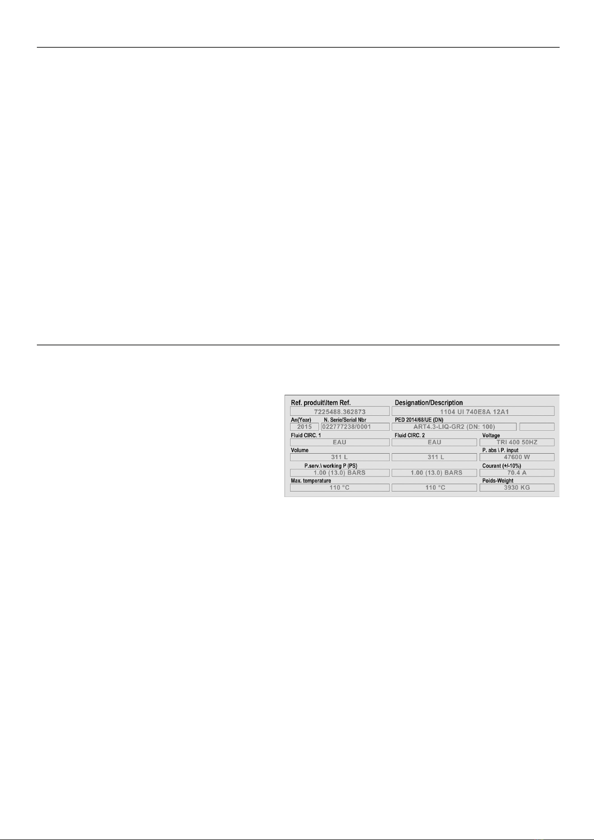
4 - NAME PLATE ................................................................................................................................................................................5
4.1 - Designation ...............................................................................................................................................................................5
5 - INSTRUCTIONS FOR LIFTING AND TRANSPORTATION .......................................................................................................... 6
5.1 - Handling units using rings xed to the roof: standard units.......................................................................................................6
5.2 - Handling units using sling stops xed underneath: special units ..............................................................................................7
5.3 - Transport ...................................................................................................................................................................................7
6 - STORAGE......................................................................................................................................................................................7
7 - LOCATION.....................................................................................................................................................................................8
7.1 - Maximum permitted wind speed................................................................................................................................................8
7.2 - Floor mounting ..........................................................................................................................................................................8
8 - INSTALLATION RECOMMENDATIONS ....................................................................................................................................... 9
9 - CONNECTIONS...........................................................................................................................................................................10
9.1 - Electrical connection ...............................................................................................................................................................10
9.2 - Fluid connection ......................................................................................................................................................................10
9.3 - Connecting a speed regulator .................................................................................................................................................10
10 - OPERATION .............................................................................................................................................................................. 11
10.1 - First commissioning............................................................................................................................................................... 11
10.2 - If anomalies occur.. .............................................................................................................................................................. 11
10.3 - Recommendations for use .................................................................................................................................................... 11
11 - AC FAN MOTOR ASSEMBLIES................................................................................................................................................12
11.1 - AC motor protection...............................................................................................................................................................12
11.2 - Fan with AC motor (3-ph 230 V/400 V 50 Hz) .......................................................................................................................12
11.3 - Fan with AC motor 3-ph 208 V and 3-ph/400 V to 480 V 60 Hz............................................................................................12
12 - EC FAN MOTOR ASSEMBLIES................................................................................................................................................13
12.1 - EC motor protection ..............................................................................................................................................................13
12.2 - Fan with EC motor (3-ph 380 V to 480 V 50/60 Hz)..............................................................................................................13
13 - MAINTENANCE.........................................................................................................................................................................14
13.1 - Recommendations for maintenance......................................................................................................................................14
13.2 - Maintenance frequency.........................................................................................................................................................14
13.3 - Cleaning the coils..................................................................................................................................................................14
13.4 - Removing and retting a fan .................................................................................................................................................15
14 - PROTECTION CABINET OPTION............................................................................................................................................17
15 - CONTROL CABINET WITH ELECTRONIC BOARD OPTION.................................................................................................18
16 - CONTROL CABINET CONTROLLED BY THE CHILLER OPTION (AUX1) ............................................................................ 20
17 - ELECTRICS BOX OPTION .......................................................................................................................................................21
18 - STAGING FOR CONTROL CABINET AND CONTROL CABINET CONTROLLED BY THE CHILLER OPTIONS (AUX1).... 22
19 - SPECIAL INFORMATION FOR ATEX AREAS .........................................................................................................................23
19.1 - General information...............................................................................................................................................................23
19.2 - Periodic inspections/checks ..................................................................................................................................................24
19.3 - Using tools in an explosive atmosphere................................................................................................................................25
19.4 - Appendix................................................................................................................................................................................26
20 - DESTRUCTION OF THE UNIT..................................................................................................................................................27
CONTENTS
3

1 - RECEIVING THE UNIT
1.1 - General checks
■Each unit has a data plate bearing an identication number. This number must
be included in all correspondence. Ensure that it is the correct unit by checking
the purchase order.
■After unpacking the unit, please inspect it for any damage.
■If any items are missing or in case of damage, specify this on the delivery slip
and inform the carrier by registered letter within 3 days of delivery of the unit.
1.2 - Unloading
■The recipient shall be responsible for unloading the equipment and providing
the necessary handling equipment (see the section entitled "LIFTING
INSTRUCTIONS").
2 - SAFETY INSTRUCTIONS
■ Any operation must be carried out by qualied personnel using the appropriate Personal Protective Equipment (PPE).
■Before any operation, read this guide carefully and keep it in a safe place. Safety information must be adhered to.
■The units must not be run under operating conditions which are more restrictive than those it was designed for (pressure,
temperature, type and circulation of uids).
■For units installed in European Community countries, ensure that the entire installation complies with the directives and
legislation in force.
■Respect the instructions for using slings (see the labels on the unit).
■To prevent any risk of accident, prohibit public access by clearly marking the work area.
2.1 - In an emergency
■Switch off the electrical supply.
■The process should not be jeopardised if the emergency stop devices are activated.
■Switch off the fans.
2.2 - The 4 main risks
■Lifting or positioning = Accident
■Contact with the piping = Burns
■ Opening the electrics box = Electrocution
■Removing the grilles = Injury
4

3 - GENERAL INFORMATION
3.1 - Unit functions
■Drycooler: Device in which a uid in liquid state is cooled by heat exchange with the ambient air, without direct contact between
the ambient air and the uid.
■ Misting option: System for cooling air by misting of water droplets under high pressure.
■ These devices must only be used for the purpose for which they are intended. In particular, it is formally prohibited to use any uid
other than that specied in the order documents.
3.2 - Standards
■ Every unit meets standards EN 60-204 as well as the following European directives:
-Machinery 2006/42/EU
-EMC 2014/30/EU
-PED 2014/68/EU
■Technicians who install, commission, operate and service the unit must understand the instructions given in this manual and be
familiar with the specic technical characteristics of the installation site.
3.3 - Warranty
■See general terms and conditions of sale.
■ Check the compatibility of the uid with the equipment being used.
■ To nd out the limits of use, refer to the name plate.
4 - NAME PLATE
■Désignation\Description: See "Description".
■An (Year): Year of manufacture.
■N° série/Serial Nbr: number to be quoted in all
correspondence.
■DIR 2014/68/EU (DN): Category and determining value
(DN for "PIPES", Capacity for "CONTAINERS").
■Fluid CIRC. 1: nature of uid in circuit 1.
■Fluid CIRC. 2: nature of uid in circuit 2.
■Voltage: Power supply.
■Volume: Capacity of the circuit.
■P.Abs/P.Input: Power input.
■P.serv.\ Working P (PS): Operating pressure. (Maximum allowable pressure set out in European Directive 2014/68/EU).
■Current (+/-10%): Maximum current.
■Max. temperature: Maximum permitted temperature.
■Poids/Weight: Maximum empty weight including options and accessories.
4.1 - Designation
E.g.: 1 10 4 UI 740 E 8A 12A1
10: Number of fans:
4: Number of rows of nned tubes: 3 or 4
740: Rotation speed (rpm)
E: Motor type:
A = AC motors (3-ph/400 V/50 Hz),
B = AC motors (other voltages),
E = EC motors,
X = ATEX motors,
M = 1 stage with EC motors.
8A: Motor impeller: 9A/9B/9C/9D = impeller Ø 910 mm,
8A/8B/8C/8D = impeller Ø 800 mm,
12A1: Type of ns: 12A1 = Tube Ø 12.7 mm,
16B2 = Tube Ø 16/15.87 mm.
5

5 - INSTRUCTIONS FOR LIFTING AND TRANSPORTATION
■The weights are given on the data plates.
■ To lift the units, it is essential to refer to the yellow lifting labels afxed to the unit and x the slings to the slinging points shown on
these
The lifting mode is shown on the dimensional drawing supplied with the order.
5.1 - Handling units using rings xed to the roof: standard units
Standard units from 6 to 16 FMAs
Yellow "Lifting
instructions" sticker
x6 x8 x10 x12 x14 x16
Wmm 3450 2300 3450 2300 3450 4600
Standard units from 18 to 20 FMAs
Yellow "Lifting
instructions" sticker
x18 x20
Mmm 2300 2300
Nmm 1150 2300
6

5 - INSTRUCTIONS FOR LIFTING AND TRANSPORTATION
5.2 - Handling units using sling stops xed underneath: special units
e.g.: C5M, copper ns, STAINLESS STEEL pipe wiring bundles, ATEX, STAINLESS STEEL casing.
Textile slings only
Yellow "Lifting instructions" sticker
Slings
Sling stop
x6 x8 x10 x12 x14 x16 x18 x20
Wmm 3390 4540 5690 6840 4600 4600 6900 6900
Hmm 4100 4100 5000 6000 4100 4000 6100 6100
As the lifting mode is related to the weight of the unit, it is essential to refer to the dimensional drawing for the unit ordered.
5.3 - Transport
■ Do not allow any disruption to the ow
■ Follow the handling instructions afxed to the packages
■Follow the lashing instructions in the document provided
■Do not stand on the packages
■Do not place anything on top of the packages
■Strap the packages onto the deck of the truck
■ Only textile straps are authorised (lifting and coupling)
■Use the dedicated option for container transport
6 - STORAGE
■Store the units at a temperature of between -40 and +60°C (temperature range for standard units). For options, see the relevant
description.
■Protect the units against impacts and ensure that they only support their own weight.
■ Place the units on rm, at and level ground. For storage in very windy areas, afx the unit to the ground using straps or cables.
■Leave the blanking trim for the pipes in place before connecting the unit.
■ For long-term storage (over 3 months), ll the exchanger with an inert gas and seal the pipes using caps. This is necessary to
prevent the formation of condensation and oxidation. Warning: do not exceed the maximum operating pressure indicated on the
data plate.
■For long-term storage, it is recommended to place the units in an area protected from adverse weather conditions.
7

7 - LOCATION
■For structures with a "special" seismic risk, please consult us.
■ Before setting up the unit in its intended location, the installer must check the following points:
-The unit must be installed outdoors in an area protected from ooding. Ensure that all conditions have been taken into account
(negative outdoor temperatures, corrosive atmosphere, altitude, etc.)
-The ground surface or structure must be level and strong enough to bear the unit's weight.
-Raise the unit if it is installed in a snowy area, in order to ensure a sufcient air intake height.
-At the design stage, check that the installation location is compatible with the unit's sound level.
-Protect the unit from sandstorms using the appropriate infrastructure.
-Waste from vegetation is a major factor contributing to the clogging of the coil; avoid installing the unit close to deciduous trees.
-Do not install the unit near hot air extraction duct outlets.
■The installer must take all necessary precautions to limit the recycling of hot air and ensure a good air supply to the unit.
7.1 - Maximum permitted wind speed
■ Maximum permitted speed once the unit is secured to the oor: 100 Km/h
■ For speeds > 100 Km/h, contact us.
7.2 - Floor mounting
Fluid input side
Allow at least 3 support zones under each foot; these zones should all be stable and on the
same horizontal plane.
(Models 6, 10, 14, 18)
(Models 8, 12, 16, 20)
8

8 - INSTALLATION RECOMMENDATIONS
■ Ensure sufcient devices are provided to guarantee the protection of persons and property, and to enable maintenance operations
to be carried out in complete safety.
■ If a malfunction would have signicant human, environmental or nancial consequences, take appropriate steps to limit the effects.
■ Ensure that the installation complies with the legal texts and codes in force in the country of operation, and that it complies with the
safety rules applicable to the site where it is being used (explosive atmosphere, for example).
■ If necessary, afx to the machine the hazard symbol corresponding to the uid in accordance with current standards.
■ Install burn hazard signs wherever the internal temperature of pipes exceeds 65°C.
■Fit safety devices to prevent the uid temperature or pressure from exceeding the values indicated in the order. Approval for operation
at higher conditions must be obtained from us.
■ The unit must be tted with an immediately accessible emergency stop device; this visible device must allow the electrical supply
to the unit and its accessories to be cut completely.
■Ensure that cutting off the electrical supply, whether intentionally or accidentally, does not jeopardise the process.
■Use the mounting holes and, if necessary, reinforce the anchoring system according to the wind conditions.
■If the unit needs to be installed on a framework, this structure must be calculated based on the weight of the unit during operation
(full), equipped with all its accessories.
■If using rubber mounts, use a rigid frame which locks the feet together.
■ The nned components may be damaged if the unit suffers impacts or is hit by falling objects. Take appropriate steps to protect it,
by adding a protective screen, for example.
■If there is a risk of freezing while the system is operating, use a device designed to prevent this.
■Install venting and draining devices and shut-off valves.
■Connect the piping to earth in accordance with an overall study of the installation.
■ For any accessories, refer to the specic guides.
9

9 - CONNECTIONS
9.1 - Electrical connection
■All wiring must be connected in accordance with the regulations that apply to the installation site (e.g. NF C 15100 in France).
■In all cases, refer to the "ELECTRICAL CONNECTION" document or wiring diagram attached to the unit.
■ Follow the electrical supply specications indicated on the data plate.
■ The phase unbalance must not exceed ±2% for voltage.
■For units without wiring or with an electrics box option, the motors are partitioned in pairs: M1+M2 – M3+M4 - …
The motors must be controlled by stage in a single partition.
If any of the above requirements are not met, immediately contact your energy supplier and make sure the unit is not switched on until
the necessary corrective actions have been taken. Failure to do so will automatically void the warranty.
It is your responsibility to protect the unit from mains voltage spikes and voltage spikes caused by lightning. Depending on
the geographic location and the type of mains network (buried or overhead), local regulations may require that a lightning rod
be installed. Failure to comply with the requirements of standards in force in the country of installation
(e.g. NF C 15100 in France) will void the warranty.
-Before connecting, make sure that the power supply cable is disconnected.
The terminal boxes on the motors for units without the terminal box or electrical cabinet option must be directly connected taking all
the necessary precautions in order to avoid:
-electrical connection errors which can damage the motors or impair performance
-water ingress in the terminal boxes (e.g. if the cover is not closed properly) which damages the motors
-people falling from a height when making electrical connections for units installed high up
9.2 - Fluid connection
■Never introduce foreign bodies into the circuit.
■ The connection pipes and the regulation or insulation equipment must be set up and supported so as to ensure they do not exert
any force on the coil piping (pressure, torsion or exion). It is recommended to use exible connectors on the connections to prevent
water hammer.
■ Positioning of pipes: connect all piping on the unit (see dimensional drawing)
■If brazed/welded connections are used, take appropriate precautions to ensure that welding residues do not enter the circuit.
9.3 - Connecting a speed regulator
■ A regulator must be commissioned by a specialist, as an incorrect choice/conguration could cause electromagnetic interference and
damage to the motors. Minimum precautions:
-Use a shielded cable upstream and downstream of the regulator.
-The frequency must be between 25 and 50 Hz.
-Fit a DU/DT lter between the speed regulator and the fans.
10

10 - OPERATION
10.1 - First commissioning
■Read the guides for commissioning any accessories very carefully and follow all advice.
■Check that the supply voltage corresponds to that given on the data plate.
■ Retighten the connections of the electrics box.
■Switch the unit on and check that all the fans are turning in the correct direction (direction of rotation shown on the labels).
In the event of abnormal noise coming from the fan motor assemblies, immediately switch off the power supply and contact us.
■Ensure that the hydraulic circuit(s) are clean.
■Start charging by bleeding the air remaining in the circuit using the vents provided in the top section.
■Start increasing the pressure, then check that the pipe connections are fully sealed.
10.2 - If anomalies occur..
Please contact us if you require any help. Before contacting your CIAT agency, please check the following points:
-Are all fans turning in the correct direction? (check this against the labels)
-Is the supply voltage correct?
-Are the motors running at the correct speed? (check the input current)
-Has the uid direction been reversed during connection of the coil?
-Are the ns of the coil clogged?
-Are there any issues relating to air recycling or a poor air supply?
10.3 - Recommendations for use
Scaling and corrosion have a very negative effect on the operation and service life of the units. Therefore, only use treated
water or authorised uids (check the compatibility of any additives with the drycooler's materials).
11

11 - AC FAN MOTOR ASSEMBLIES
11.1 - AC motor protection
■ All the motors are equipped with a thermal cut-out, which is available in the motor terminal box. Wiring for the thermal cut-out is
optional
11.2 - Fan with AC motor (3-ph 230 V/400 V 50 Hz)
■ On a 3-ph/400 V/50 Hz network, the motors have 2 rotation speeds, via star (Y) or delta connection (Δ).
-Low speed with Y connection
-High speed with Δ connection
■ On a 3-ph/230 V/50 Hz electrical network, the motors have 1 rotation speed via delta connection (Δ):
-Low speed with Δ connection
Impeller diameter mm 910 800
Motor type A9A A9B A9C A9D A8A A8B A8C
3-PH/230 V supply Δ-Δ-Δ-Δ-Δ-Δ-Δ-
3-PH/400 V supply Y ΔYΔYΔYΔYΔYΔYΔ
Speed(s) rpm 690 900 980 1280 680 890 700 900 700 900 560 690 300 440
Weight of impeller + motor kg 23 - 28 - 28 19 -
Weight of fan motor assembly kg 70 59 66 59 52 48 38
Min. room temperature for storage °C -40
Min. operating temperature °C -40
Insulation class F
Sealing class IP 54
Number of starts Max. 50 / hour
11.3 - Fan with AC motor 3-ph 208 V and 3-ph/400 V to 480 V 60 Hz
■ On a 3-ph 208 V/60 Hz and 230 V/50 Hz electrical network, the motors have 1 rotation speed via delta connection (Δ).
■ On a 3-ph/400 to 480 V/60 Hz electrical network, the motors have 1 rotation speed via star connection (Y):
Impeller diameter mm 910 800
Motor type B9A B9B B9C B8A B8B B8C B8D
3-ph 208 V/60 Hz supply ΔΔΔ - - Δ Δ
3-ph/400 to 480 V/60 Hz supply Y Y Y Y Y Y Y
Speed(s) rpm 1100 1000 800 1100 1050 840 520
Weight of impeller + motor kg 28 25 25 23 23 19 19
Weight of fan motor assembly kg 69 66 66 51 51 47 47
Min. room temperature for storage °C -40
Min. operating temperature °C -40
Insulation class F
Sealing class IP 54
Number of starts Max. 50 / hour
12

12 - EC FAN MOTOR ASSEMBLIES
12.1 - EC motor protection
■These motors feature integrated protection and monitoring devices. They are protected against thermal overload of the electronic
components and motors, and against any failure of the Hall effect sensors to analyse the position of the rotor.
■ These faults are indicated by a change of state in the KL2 fault relay (terminals COM-NO-NC). This is a potential-free changeover
relay, with a breaking capacity of 2 A/250 VAC cos phi = 1.
■ List of faults:
-In the event of a thermal overload on the motor/electronic controls, or a Hall effect sensor fault:
The fan stops and cannot be restarted. The fault is indicated by a change of state on the KL2 relay. The fan can only be restarted
by powering off for 20 seconds then powering back on again (after the source of the fault has disappeared, otherwise the cycle
restarts).
-Rotor blockage:
In the event of accidental rotor blockage, the fault is indicated by a change of state on the KL2 relay. When the blockage is
cleared, the fan automatically restarts.
-Under voltage:
The motor accepts a nominal voltage/frequency range of 380 to 480 V/50 to 60 Hz with no notable modication to a handling
performance. Between 380 and 290 V, the fan continues to operate with degraded performance. If the voltage drops below 290
V for 5 seconds, the motor stops. The fault is indicated by a change of state on the KL2 relay. The motor will restart when the
voltage returns to its nominal value.
-Absence of phase:
If one of the 3 phases is absent for more than 5 seconds, the motor stops. The fault is indicated by a change of state on the
KL2 relay. The motor will automatically restart 10 - 40 seconds after the 3 phases return. Phase inversion has no effect on the
direction of rotation of the motor.
12.2 - Fan with EC motor (3-ph 380 V to 480 V 50/60 Hz)
■On a 3-ph/380-400 V/50/60 Hz network, EC motors will have different rotation speeds depending on the control signal.
Impeller diameter (mm) 910 800
Supply voltage 3-PH/380 - 480 V/50/60 Hz supply
Control signal 0/10 V or 4/20 mA
Motor type E9A E9B E8A E8B E8C
Max. speed(s) rpm 1000 1100 740 510 700
Weight of impeller + motor kg 25 - 20 9 -
Weight of fan motor assembly kg 65 45 40 38 26
Min. room temperature for storage °C -40
Min. operating temperature °C -25 -35 -25 -40 -35
Insulation class F
Sealing class IP 54
Number of starts Max. 50 / hour
13

13 - MAINTENANCE
13.1 - Recommendations for maintenance
■Make sure power to the unit has been disconnected before servicing.
■Reduce the temperature and pressure before carrying out any work on the bundle.
■ Do not make any modications without our agreement.
■Do not walk directly on the unit.
■ Depending on the type of uid (e.g. water without anti-freeze), take precautions to prevent the risk of freezing, which would destroy
the coil. As standard units cannot be completely drained by gravity, protect from freezing as follows:
1. Drain the circuit using the bleed nozzles and the vent located on the manifolds or pipes.
2. Circulate compressed air through the circuit until all water has been removed.
3. Fill the circuit with anti-freeze and close the circuit.
■For regulated units, do not forget the mandatory inspections.
■In winter, do not allow snow to accumulate around and on top of the unit.
■Periodically check the condition of the coatings and apply touch-ups as needed.
13.2 - Maintenance frequency
ACTION FREQUENCY
Retighten nuts and bolts on fan motor assemblies (grille, motor). 6 months
Check and, if necessary, retighten the packing boxes and the terminal box mounting bolts 6 months
Clean the coil. 1 year (1)
Retighten the electrical connections. 1 month after system start-up then 1
year
Retighten all visible nuts and bolts. 1 year
Check for corrosion to the panelling and that the safety labels and name plate label are present. 1 year (1)
Clean the louvres on the electrical cabinet (optional) 1 year
Check the electrical cables. 5 years
(1) Frequency to be adapted to the environmental conditions.
13.3 - Cleaning the coils
■Switch off the unit.
■ If the unit is tted with a "protective screen" option, remove this to access the coils.
■ If the ns are damaged, straighten them using a comb.
■ In the event of minor fouling (non-clogging dry residue or dust, leaves, wires, etc.):
-Counter-ow supply air: dry air up to 30 bar.
-Where possible, periodically reversing the ow of air generated by the fans can prevent this. This operation is not possible if the
unit is equipped with EC motors.
■In the event of moderate fouling (moderate clogging due to dry residues, damp dust or grass, insects, etc.):
-Use a high-pressure (HP) steam cleaner with a at jet nozzle (25°).
-Max. pressure 100 bar
-Steam: max. 140°C
-Min. distance between the nozzle and the ns = 200 mm
-Cleaning uid: municipal water with pH neutral detergent (pH 7). Avoid alkaline detergents.
-Flushing with clean water using the same adjustment parameters.
■IMPORTANT: the use of detergent is prohibited for cleaning ns with a BLYGOLD®, ALTENA®or HERESITE®coating.
Recommendations to follow when using a HP cleaner
1. Wait for the HP cleaner to fully warm up. Check that the uid exiting the nozzle is steam
rather than liquid.
2. Hold the high-pressure cleaner's lance at a distance greater than that recommended,
then move forward into the working position.
3. Direct the at jet created by the nozzle onto the surface of the ns and perpendicular to
them. An angled position risks pushing the ns together and a parallel position risks
pushing them apart.
4. To prevent residue from being pushed inside the nned block, it is often useful to perform
an initial wash against the air ow direction (at the discretion of the operator and depending
on the fouling level).
5. Some detergents may damage the unit's paintwork. NO
NO
YES
14

13.4 - Removing and retting a fan
■ The removal of a fan is a simple operation, however special care must be taken during handling, in particular:
-Do not pull on the blades.
-Place the fan motor assembly on a safe surface away from areas of activity.
-If the unit is to be shipped, provide the necessary protection and packing materials.
-Do not remove the panel.
■The fan must be repaired if any of the blades are bent.
Operating procedure for motor types A9A, A9C, A8A, A8B,E9A, E8A, E8B, M9, M8, B9A, B9B, B9C, B8A, B8B, B8C and B8D:
Switch off the power supply using the mains switch or maintenance switch (optional).
■ Disassembly:
1. Remove the cover from the motor's terminal box.
2. Disconnect the wires, marking the terminals to facilitate rewiring.
3. Loosen the cable gland(s) on the terminal box and pull out the cable. Remove the clamps
connecting it to the fan support arm.
4. Remove the 4 M8 bolts mounting the fan on the collar (T40 torx type spanner).
WARNING: do not unscrew the motor mounting bolts.
5. Remove the fan using the lifting lugs.
■ When retting, position the fan on the 4 collar inserts then carry out the operations in
the reverse order to removal, ensuring only the M8 bolts provided are used (tightening torque 16 Nm).
■ Before turning the unit back on, make sure:
-the ends of the blades do not touch the collar (centring of the blades in their collar): rotate the impeller by hand.
-the wiring is correct and the terminals are properly tightened.
-the motor terminal box seal is correctly in place and that the bolts keeping it closed are torque tightened to 1.5 ± 0.2 Nm (risk of
rainwater ingress).
-the packing boxes are properly tightened
Operating procedure for motor types A9B, A9D, A8C, E9B and E8C:
Switch off the power supply using the mains switch or maintenance switch (optional).
■ Disassembly:
1. Remove the fan protective grille
2. Remove the cover from the motor's terminal box.
3. Disconnect the wires, marking the terminals to facilitate rewiring.
4. Loosen the cable gland(s) on the terminal box and pull out the cable. Remove the clamps
connecting it to the fan support arm.
5. Remove the 12 bolts mounting the fan on the unit.
6. Remove the fan using lifting hooks in the ø12 mm holes
Ø 12 mm 8 turns to be used
to install the lifting hooks
Do not use the holes in the
shaded areas
IMPORTANT: the handling hooks must be positioned diametrically opposite the widest parts of the fan's
collar edge.
13 - MAINTENANCE
15

■ To ret, position the fan on the 12 unit inserts and carry out the operations in the reverse order to removal, using only the bolts
provided:
-M8x25 bolts and at washer for V units (tightening torque 12 Nm).
-M10x25 bolts for atbed units (tightening torque 24 Nm).
M8x25 bolts and at washer M10x25 bolts
Torx bolts for protective grille
(tightening torque 6 Nm).
■ Before turning the unit back on, make sure:
-the ends of the blades do not touch the collar (centring of the blades in their collar): rotate the impeller by hand.
-the wiring is correct and the terminals are properly tightened.
-the motor electrics box seal is correctly in place and that the bolts keeping it closed are tightened to 2.5 Nm for ECs and
1.3 Nm for ACs. (risk of rainwater ingress).
-the cable glands are properly tightened.
13 - MAINTENANCE
16

14 - PROTECTION CABINET OPTION
Purpose
■Protects the motors
Power supply
■See connection sheet or wiring diagram supplied with the cabinet.
Limits of use
■ Ambient air:
-Storage temperature: -40/+60°C
-Operating temperature: -25/+55°C
Components
■ Packing boxes are provided for the installer on the base of the cabinet.
■ A padlockable front disconnect switch, with auxiliary contact, tted with a device requiring the power supply to be switched off before
the door is opened. This works as an emergency stop.
■ One thermal-magnetic circuit breaker for each motor, padlockable with normally open auxiliary contact.
■ 1 x 3-stage terminal (1, 2, PE) for each fan line for 0/10 V signal (EC FMA option).
Electrical connection
■The motors are connected to the front of the mounted cabinet on the inlet manifold side.
■For electrical connection, refer to the connection sheet or wiring diagram supplied with the cabinet.
■The cables to use for the power connection must be made from copper. If cables made from other materials, such as aluminium,
are used, bimetallic terminals and connectors or intermediate terminals must be used.
■ Make the electrical connections as follows:
-Connection of the power circuit to the main switch.
-Connection of the protective conductor to the earth terminal.
-Connection of 0/10 V signal (EC fan motor assembly option) on 3-stage terminals (1, 2, PE) 1 terminal available for each fan line.
-A single common value of 0/10 V must be connected on the two terminal strips provided for this purpose
Information available
■See connection sheet or wiring diagram supplied with the cabinet.
■ On dry contacts:
-Switch position feedback
-Fault summary (failsafe)
17

15 - CONTROL CABINET WITH ELECTRONIC BOARD OPTION
Purpose
■Protects and controls the motors. The control electronic board makes it possible to control the temperature or pressure, monitor
the operating parameters, communicate with certain chillers, diagnose and store faults and communicate with the remote control
console, additional boards or a BMS.
Power supply
■See connection sheet or wiring diagram supplied with the cabinet.
Limits of use
■ Ambient air:
-Storage temperature: -40/+60°C
-Operating temperature: -25/+55°C
Components
■ Packing boxes are provided for the installer on the base of the cabinet.
■A lockable isolator switch is used as an emergency stop.
■ Protection against short circuit provided by 1 or 2 three-pole circuit breakers (ICC = 10 KA)
■ Protection against overload: thermal cut-out wiring on electronic board.
■ 1 x 230 V switch per stage.
■1 Electronic board.
■ 1 x console with LCD screen optional for condenser.
■ Fluid temperature sensor (drycooler): mounted on the outlet piping (control sensor).
Electrical connection
■Before connecting, make sure that the machine's disconnect switch is open
■The cabinet is connected to the motors and mounted on the front of the unit, on the inlet manifold side.
■For electrical connection, refer to the connection sheet or wiring diagram supplied with the cabinet.
■The cables to use for the power connection must be made from copper. If cables made from other materials, such as aluminium,
are used, bimetallic terminals and connectors or intermediate terminals must be used.
■ The electrical connections are to be made as follows:
-Connection of the power circuit to the disconnect switch after checking that the power supply cable is disconnected.
-Connection of the protective conductor to the earth terminal.
-Connection for automatic operation control
-Connection for changing the setpoint.
-Connection for fan forced operation
■ Outdoor temperature sensor (drycooler):
-The machine should be positioned so as to enable the outdoor sensor to be installed on the building's closest northern side.
If necessary, the sensor must be positioned on the northern side of the unit, away from moving air (fan, etc.). If none of these
conditions can be met, the customer must install a weather mast. (Not supplied)
-The sensor cable must be protected against external harmful elements.
-Make sure the outdoor sensoris not exposed to direct sunlight, and place it in a vertical position:
18

Electronic board functions.
■See the user manual for the electronic board.
Options
■400/230 V transformer for the control circuit, for 400 V 3-phase supplies without neutral.
■ Water loop temperature sensor (drycooler) to be installed with freecooling upstream of the valve: Fluid 90 °C max. – 6 m cable – G
1/2" sensor pocket.
■ Pressure sensor (condenser): 35 bar max. (optional 50 bar max.) – mounted on the "are" union on the inlet piping.
■ Remote control console: max. distance: 1000 m. To be installed locally.
Dimensions (L x H x D): 102 x 235 x 55 mm.
■ Relay board: this has potential-free (dry) contacts for remotely displaying the following parameters: unit operation, sensor faults
and fan stage faults. The boards must be installed in a cabinet.
■Electrical power measurement.
Ventilation
■ Louvres with lters are tted on the sides of the cabinet. As an option, a fan may be added for use from 45 to 55°C.
Heating
■As an option, a heater connected to a temperature sensor may be added for use from -20 to -40°C.
Humidity
■ As an option, a heater connected to a humidity sensor may be added for use above 60% humidity.
Information available
■See connection sheet or wiring diagram supplied with the cabinet.
■ On dry contacts:
-Switch position feedback
-Operating information
-Fault summary (failsafe)
15 - CONTROL CABINET WITH ELECTRONIC BOARD OPTION
19

16 - CONTROL CABINET CONTROLLED BY THE CHILLER OPTION (AUX1)
Purpose
■Protects and controls the motors. The electronic board enables communication with certain chillers that have the board embedded,
allowing the temperature or pressure to be used for control.
Power supply
■See connection sheet or wiring diagram supplied with the cabinet.
Limits of use
■ Ambient air:
-Storage temperature: -40/+60°C
-Operating temperature: -25/+55°C
Components
■ Packing boxes are provided for the installer on the base of the cabinet.
■A lockable isolator switch is used as an emergency stop.
■ Protection against short circuit provided by 1 or 2 three-pole circuit breakers (ICC = 10 KA)
■ Protection against overload: thermal cut-out wiring on electronic board.
■ 1 230 V switch per stage, except variable speed fans (EC) which do not have a switch.
■1 Electronic board.
■ Temperature sensor (drycooler): mounted on the outlet piping (control sensor).
Electrical connection
■Before connecting, make sure that the machine's disconnect switch is open.
■The cabinet is connected to the motors and mounted on the front of the unit, on the inlet manifold side.
■For electrical connection, refer to the connection sheet or wiring diagram supplied with the cabinet.
■The cables to use for the power connection must be made from copper. If cables made from other materials, such as aluminium,
are used, bimetallic terminals and connectors or intermediate terminals must be used.
■ The electrical connections are to be made as follows:
-Connection of the protective conductor to the earth terminal.
-Connection of the power circuit to the disconnect switch after checking that the power supply cable is disconnected.
■ Outdoor temperature sensor: 25 m cable
-The machine should be positioned so as to enable the outdoor sensor to be installed on the building's closest northern side. If
necessary, the sensor must be positioned on the northern side of the unit, away from moving air (fan, etc.). If none of these
conditions can be met, the customer must install a weather mast. (Not supplied)
-The sensor cable must be protected against external harmful elements.
-Do not expose the outdoor sensor to direct sunlight.
Electronic board functions.
■Refer to the chiller manual.
Options
■400/230 V transformer for the control circuit, for 400 V 3-phase supplies without neutral.
■ Water loop temperature sensor (drycooler) to be installed with freecooling upstream of the valve: 25 m cable G 1/2" sensor pocket.
Ventilation
■ Louvres with lters are tted on the sides of the cabinet. As an option, a fan may be added for use from 45 to 55°C.
Heating
■As an option, a heater connected to a temperature sensor may be added for use from -20 to -40°C.
Humidity
■ As an option, a heater connected to a humidity sensor may be added for use above 60 % humidity.
20
Table of contents
Other Carrier Freezer manuals

Carrier
Carrier 2SF-13 User manual

Carrier
Carrier PH61 User manual

Carrier
Carrier 50gs sizes 018-060 Installation manual

Carrier
Carrier Transicold 69NT40-561-199 Operation manual

Carrier
Carrier NEOS 100S User manual

Carrier
Carrier B5 Installation instructions

Carrier
Carrier EC 2709N User manual

Carrier
Carrier 60 User manual

Carrier
Carrier 50CD User manual

Carrier
Carrier C302 NPR User manual
Popular Freezer manuals by other brands

Metos
Metos Econo BD-600W Installation and operation manual

Frigidaire
Frigidaire FFU20F9G Factory parts catalog

Beko
Beko RCNA400E40ZXP manual

SPX Cooling Technologies
SPX Cooling Technologies Evaporative Air Cooler FSIG-TS-08A engineering data

ChiQ
ChiQ CSF085DW user manual

Whirlpool
Whirlpool EH15VSXL Use and care guide